1
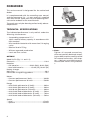
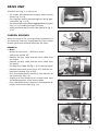
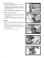
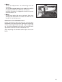
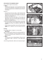
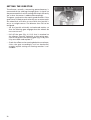
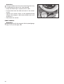
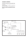
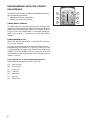
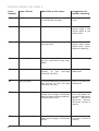
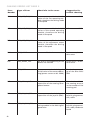
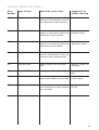
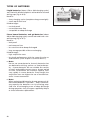
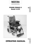
The Motivation.
GB
ELECTRONIC WHEELCHAIR
ELECTRONIC WHEELCHAIR
OPTIMUS
SERVICE MANUAL
1
Table of contents
Foreword ................................................................................................................................ 4
Technical Specifications ................................................................................................................... 4
Drive unit................................................................................................................................ 5
Carbon brushes ................................................................................................................................ 5
Removal....................................................................................................................................... 5
Fitting .......................................................................................................................................... 6
Collector ...................................................................................................................................... 6
Replacing the drive unit .................................................................................................................. 7
Preparations ................................................................................................................................ 7
Removal....................................................................................................................................... 8
Fitting ........................................................................................................................................ 10
Functional checks ..................................................................................................................... 10
Brakes .................................................................................................................................... 11
Motor brake ................................................................................................................................... 11
Functionality ............................................................................................................................ 11
Drum Brakes ................................................................................................................................... 12
Adjusting................................................................................................................................... 12
Replacing the bowden cable ................................................................................................... 13
Magnetic brake .............................................................................................................................. 14
Functionality ............................................................................................................................ 14
Removal..................................................................................................................................... 15
Fitting ........................................................................................................................................ 15
Adjusting................................................................................................................................... 16
Functional checks ..................................................................................................................... 16
Replacing the bowden cable ................................................................................................... 17
Steering ................................................................................................................................ 19
Replacement ................................................................................................................................... 19
Removal..................................................................................................................................... 19
Fitting ........................................................................................................................................ 20
Alignment ....................................................................................................................................... 21
Checking the alignment .......................................................................................................... 21
Adjusting the alignment ......................................................................................................... 21
Setting the director ....................................................................................................................... 22
Tyres ...................................................................................................................................... 23
Changing the tyres ........................................................................................................................ 23
All wheels .................................................................................................................................. 23
Front wheels ............................................................................................................................. 24
CAN-Bus Control .................................................................................................................. 25
CAN-Bus hardware ......................................................................................................................... 26
Operating module.................................................................................................................... 26
Power module ........................................................................................................................... 28
Plug assignment ....................................................................................................................... 28
Adjustment module ................................................................................................................. 29
Plug assignment ....................................................................................................................... 29
CAN-Bus software .......................................................................................................................... 30
Service program ....................................................................................................................... 30
Driving programs ..................................................................................................................... 33
Programming with the operating module ................................................................................... 34
Adjustment modus ................................................................................................................... 34
Programming foil ..................................................................................................................... 34
Switching to the adjustment modus ...................................................................................... 35
Functions................................................................................................................................... 35
2
Adjusting the joystick priority ................................................................................................ 35
Adjustment of the parameters ............................................................................................... 36
Concluding the adjustment modus ........................................................................................ 37
Quick reset to standard values ............................................................................................... 37
CAN-Bus error list .......................................................................................................................... 38
Replacing the CAN-Bus modules .................................................................................................. 44
Replacement (all modules) ...................................................................................................... 44
Checking the cable layout ....................................................................................................... 45
Lighting ................................................................................................................................. 46
Replacing lightbulbs ...................................................................................................................... 46
Adjusting the headlights .............................................................................................................. 46
Batteries ............................................................................................................................... 47
Charge............................................................................................................................................. 47
Battery chargers ............................................................................................................................. 47
Types of batteries ........................................................................................................................... 48
Maintenance of liquid batteries ............................................................................................. 49
Replacement ................................................................................................................................... 49
Removal..................................................................................................................................... 49
Fitting ........................................................................................................................................ 49
Fuses ...................................................................................................................................... 50
Battery fuse .................................................................................................................................... 50
Electronic security .......................................................................................................................... 50
Maintenance ......................................................................................................................... 51
Maintenance checklist ................................................................................................................... 52
Electrical system ....................................................................................................................... 52
Mechanic ................................................................................................................................... 53
DIN norms and guidelines ....................................................................................................... 54
Notes ..................................................................................................................................... 55
3
FOREWORD
This service manual is designated for the authorized
dealer.
It is complemented with the according users manual
and the spare parts list. – A users manual is supplied
with each vehicle. Spare parts lists and operating manuals can be ordered at the manufacturer.
The work may only be done by professionally educated personnel.
1–1
TECHNICAL SPECIFICATIONS
The indicated performance is only realistic under the
following circumstances:
– Surrounding temperature 27° C
– 100% nominal battery capacity in accordance with
DIN standard
– Mint condition batteries with more than 5 charging
cycles
– Nominal load of 75 kg
– Without repeated acceleration
– Level and firm surface
OPTIMUS
Model 3.622 (fig. 1–1 and 1–2)
Electronic ............................................................... 110 A
Batteries:
– Gel batteries ....................... 60 Ah (20h), 80 Ah (20h)
– Lead acid batteries ................ 60 Ah (5h), 90 Ah (5h)
Battery charger
Main fuse .................................................................80 A
Permissible rising/falling gradient: ........................18%
Motor:
– Constant performance 6 km/h ......................... 300 W
– Constant performance 10 km/h ....................... 500 W
Range:
– with 60-Ah-gel-batteries (6 km/h) ................... 40 km
– with 80-Ah-gel-batteries (6 km/h) ................... 60 km
– with 80-Ah-gel-batteries (10 km/h) ................. 40 km
– with 60-Ah-lead-acid-batteries (6 km/h) ......... 50 km
– with 90-Ah-lead-acid-batteries (6 km/h) ......... 70 km
– with 90-Ah-lead-acid-batteries (10 km/h) ....... 50 km
Speed:
– serial .................................................................. 6 km/h
– optional .......................................................... 10 km/h
4
1–2
☞ Note:
Tighten all screwed connections,
when not specially declared, according to table torque according to DIN
for screwed connections, view chapter < Maintenance/Maintenance
checklist/DIN norms and guidelines
>.
DRIVE UNIT
The drive unit (fig. 2–1) consists of
– the motor (24V-permanent magnet direct current
motor, fig. 2–2/ A),
– the magnetic brake (electromagnetic spring pressure brake, fig. 2–2/ B),
– the maintenance free direct cogged differential gear
(fig. 2–2/ C) including the two half axles
– and the drum brakes on both sides (optional, fig. 2–
2/ D).
2–1
A
C
CARBON BRUSHES
B
When the motor is not running flawless and defects in
the incoming lines can be excluded the four carbon
brushes have to be checked one after the other.
REMOVAL
D
☞ Note:
Watch for the screws. – Will be re-used!
– Switch the vehicle off.
– Remove the plus cable and the minus cable from
the motor.
– Remove the plus cable and the minus cable from
the motor.
– Pull back the rubber lid (fig. 2–3/ E) from the motor.
– Remove the fixation screw (fig. 2–4/ F) from the carbon brush retainer (fig. 2–4/ G).
– Push the carbon brush retainer in the direction of
the screw hole (fig. 2–5).
– Slightly pull the carbon brush retainer back form
the motor opposite of the screw holder.
2–2
E
2–3
F
– Press the carbon brush retainer in the opposite direction of the screw hole (fig. 2–6).
b
g
2–4
1
2
2–5
5
– Slightly pull out the carbon brush retainer (fig. 2–
7).
☞ Note:
Two opposite carbon brushes each are connected
to each other by a cable (fig. 2–8/ H) running inside
the motor.
– Remove the philister head screw (fig. 2–9/ I) of the
connecting cable.
– Completely remove the carbon brush retainer.
☞ Note:
1.) The carbon brush retainers cannot be pulled
straight out of the opening. – Slightly turn the carbon brush retainer sideways while pulling it out.
☞ The carbon brushes are worn when the pressure
springs come to rest on the retainer without the
carbon brushes reaching over their guide way. They
are also to be replaced when contacts (fig. 2–10/ K)
appear black and blunt. – On intact carbon brushes
the contacts are anthracite coloured and shining.
☞ When one or more carbon brushes are extremely or
totally worn, all carbon brushes are to be exchanged. – As a spare part the carbon brushes are
supplied in a set completely assembled in the retainer.
– If the carbon brush is completely intact reassemble
the carbon brush retainer and check the next one.
2–6
2–7
FITTING
H
The fitting is done analogue in reverse order.
COLLECTOR
The collector (fig. 2–10/ L) located between the carbon
brushes is also to be checked for damages. – To check
them remove a carbon brush retainer.
2–8
☞ Note:
The slight grinding marks caused by the carbon
brushes correspond to their normal wear and have
no influence on the performance of the motor. Extreme recesses have to be smoothed out. If partial
segments have been broken out or are extremely
burnt the drive unit has to be replaced.
I
2–9
K
l
2–10
6
REPLACING THE DRIVE UNIT
The drive unit (fig. 2–11) can only be replaced as a complete driving unit (with the exception of the magnetic
brakes).
PREPARATIONS
– Jack up the vehicle under the battery case so that
the front wheels move freely.
– Swivel the seat up.
2–11
– Pull the battery fuse (fig. 2–12/ A) out of the fuse
holder.
– Remove the pole shoe covers from the battery poles.
– Disconnect all four cable connections from the battery poles (fig. 2–13/ B).
– Prevent the seat from swivelling down (for example with a wood strip between the seat and chassis).
A
☞ Note:
Slight tension can occur on wheelchairs with seat
inclination adjustment (Code 118) of the seat lowered completely. – Adjust to a tension free position.
– Carefully turn the button (fig. 2–14/ C) off of the
seat lock without pulling on it. In doing so hold onto
the pin of the seating lock (fig. 2–14/ D), onto which
the button is applied, with a pan head screwdriver.
!
2–12
Attention:
Only turn off the button with added security. – In
unsecured state the seat will fall down when the
button is moved. – Danger of injury!
B
2–13
D
C
2–14
7
With drum brake option
– Screw off the ball button of the drive-/push- operation selection lever (fig. 2–15/ E).
– Pull the brake lever (fig. 2–16/ F) off. – To achieve
this remove the hexagon socket thread pin (fig. 2–
16/ G) from the bushing into which the eccentric
reaches (fig. 2–16/ H).
– Remove the bowden cables on both sides from the
brake arms, view chapter < drum brakes >.
Without drum brake option
E
2–15
– Pull the brake lever off. – To achieve this screw the
inner hexagon socket thread pin (fig. 2–17/ I) out of
the eccentric shaft.
– Disengage the bowden cable from the motor and
the magnetic brake, view chapter < magnetic brake
>.
F
G
REMOVAL
– Demount the two front wheels. – For this remove
the four screws for the wheel attachment (view fig.
2–18).
– Take the front and both side panels off (fig. 2–19).
H
2–16
– Loosen the spanning belt that straps the batteries
in (view chapter < batteries/replacement >) and remove the batteries.
– Lift out the battery case (fig. 2–19/ K).
I
2–17
2–18
K
2–19
8
– Remove the cable connections for the plus and minus pole on the motor (fig. 2–20/ L).
– Open all cable binders of the right cable harness.
Cut through any binders that cannot be opened
(view fig. 2–21).
– Unlock the plug connectors of the speed sensor, the
magnetic brake and the micro-switch for push
modus, remove them from the power module and
extract the cable harness. – To unlock the locking
levers press them down on the opposite side of the
module.
l
2–20
– Lever off the ball ladle of the transverse control arm
after removing the security hanger (fig. 2–22/ M).
– Screw the stopper discs (fig. 2–23/ N) off of the rocker. – While doing so observe the following danger
indications!
!
Attention:
When removing the stopper discs hold on to the
drive so that it cannot fall down (view fig. 2–24).
After removing the stopper discs slowly lower the
drive.
– Remove the springs (fig. 2–26/ O) as well as the lower spring guides (fig. 2–26/ P).
2–21
– Screw off the screws for the attachment of the drive
(fig. 2–25/ Q). – While doing so secure the drive
against falling down.
– Remove the drive unit
M
2–22
N
2–23
2–24
9
FITTING
The fitting is done analogue in reverse order.
!
Attention:
Secure the screws for attaching the drive unit (fig.
2–26/ R) with Loctite 243!
Q
☞ Note:
The cable harness has to be repositioned. Guide the
cable in font of the resting plate (fig. 2–26/ S) and
underneath the shaft for the brake lever (also compare fig. 2–17 and 2–21). Afterward refasten the
cable harness to chassis and sea again with cable
binders.
2–25
Torque indication:
Tighten the screws for the wheel attachment with
20 Nm!
S
☞ Note:
P
After completion of all assembly work the drum
brake has to be adjusted, view chapter < drum brake/
adjustment >.
FUNCTIONAL CHECKS
Inspection during standstill
– Check all attachments and connections.
– Do a visual check of the complete vehicle.
– Switch to pushing mode and check the smooth manoeuvrability of the vehicle.
– Switch to driving mode, switch the vehicle on and
check the battery voltage.
– Check all lighting components for functionality.
Test drive
– Initially drive carefully and observe if the driving
behaviour of the vehicle has changed.
– Watch for unusual sounds.
– Conduct a braking test.
10
R
2–26
O
BRAKES
☞ Note:
Switch the vehicle off in push mode. – This makes
pushing the vehicle easier.
The vehicle is fitted with a double security system, consisting of:
– the drum brake (option),
– the motor brake and
– an electro-magnetic spring pressure brake (magnetic
brake).
MOTOR BRAKE
The function of the motor brake evolves by the type
of approach of the motor through the power electronic.
FUNCTIONALITY
With retracted driving lever the induced motor voltage is short circuited by a programmable tacting frequency that continuously brakes the vehicle down to
almost stillstand.
With the programmable tacting frequency the braking process can be adjusted from "soft" to "full-stop".
When traveling downhill the motor switches to generator operation. This effects that the energy won is fed
in to the drive batteries (energy recycling).
11
DRUM BRAKES
(Option)
A
The two drum brakes for the driving wheels are activated by the hand brake lever.
B
ADJUSTING
The drum brake is adjusted via the bowden cable.
– Jack up the vehicle and disassemble the front wheels.
– Set the brake lever to push mode.
3–1
– Pre adjust the bowden cable (fig. 3–1/ A) at the brake
arm (fig. 3–1/ B). – To do so loosen the nuts (fig. 3–2/
C) pull the core (fig. 3–2/ D) and retighten the nut.
C
– Loosen the counter nuts from the adjustment screws
(fig. 3–3/ E and 3–4/ E) and screw them back.
– Fine-tune the bowden cable by turning the adjustment screw (turning outward = spanning).
– For testing slowly move the brake lever forward and
backward and while doing so check the braking
function by turning the drums (fig. 3-3/ F).
☞ Note:
D
3–2
The bowden cable is adjusted correctly if the drum
brake already shows effect when the switching if
the micro switch (fig. 3–4/ G) can be heard.
– If necessary correct the adjustment.
– Recounter all adjustment screws.
E
– Mount the front wheels and jack the vehicle down.
F
3–3
G
E
E
3–4
12
☞ Note:
After the adjustment the following must be
checked:
a) with disengaged brake (push mode) the vehicle
has to be pushed easily (bowden cable taut).
b) While the brake is engaged the vehicle may not
be moveable at all.
H
☞ Note:
If the drum brake slips on one or both sides even
though the adjustment is correct the drive has to
be sent in for maintenance.
3–5
REPLACING THE BOWDEN CABLE
During replacement take care that the short bowden
cable cover runs from the lower adjustment screw (fig.
3–5/ H) to the right brake arm (fig. 3–5) on right side
use. For left hand operation it has to run from the lower
adjustment screw to the left hand brake arm.
After replacing the bowden cable adjust the drum
brake.
13
MAGNETIC BRAKE
A magnetic brake (fig. 3–6/ I) is flanged to the motor
(fig. 3–6/ J). After the driving wheels come to a still
stand, the magnetic brake instantly prevents rolling
on inclines or slopes.
FUNCTIONALITY
The disc form brake pad (fig. 3–7/ K) is located between
the flanged friction discs (fig. 3–7/ L) and the axially
moving anchor disc (fig. 3–7/ M) and is mounted swivel proof through a hub to the motor shaft.
I
J
3–6
Braking condition
l
K
M
In a powerless state of the brake (this corresponds to a
standstill of the vehicle) a central pressure spring (underneath the piston, fig. 3–8/ N) presses the brake pad
over the anchor disc against the friction disc. This prevents a rotation of the motor. – Over the motor and
the connected drive the vehicle is prevented from rolling.
Driving condition
3–7
With the battery current engaged the brake magnet
(fig. 3–8/ O) creates a magnetic field that pulls the anchor disc against the force of the central pressure disc.
O
– Through this the brake pad and the motor shaft connected via the swivel proof hub can now move freely.
The wear of the pads can make an adjustment or replacement of the pads necessary.
N
Push mode
In the push modus the central pressure spring is mechanically pulled away and sets the brake pad free.
3–8
With drum brake option
The central pressure spring is pulled back by throwing
the drive-/push modus lever (fig. 3–8).
Without drum brake option
The central pressure brake is pulled back by the by the
brake hanger (fig. 3–9).
3–9
14
REMOVAL
– Remove the front panel.
– Without drum brake option: Set the brake lever to
push mode. Disassemble the brake bowden cable,
view chapter < magnetic brake/replacing the bowden cable >.
Q
P
– With drum brake option: Set the selection lever (fig.
3–10/ Q) to push mode.
Removal and installation of the magnetic brake is done
with 3 hexagon socket screws (fig. 3–10/ P).
R
3–10
– Remove the hexagon socket screws (fig. 3–9) and
take out the magnetic housing together with the
anchor disc and adjustment pieces (fig. 3–10/ R) from
the motor.
– Pull the brake pad from the swivel proof hub on the
motor shaft.
☞ Note:
The brake pad must easily let itself be pulled off of
the star formed tappet. – Otherwise work the teething of the brake pad with a key file until they fit
faultlessly.
3–11
– Remove the friction disc from the motor.
FITTING
The fitting is done corresponding in reverse order
fig. 3–11 and 3–12).
!
!
Attention:
After fitting the magnetic brake has to be readjusted, view chapter < Adjustment >.
Attention:
If the tappet has to be removed from the motor
shaft you have to check for the correct position of
the hub when witting if back on. The hub side of
the tappet has to face away from the motor.
3–12
15
ADJUSTING
!
S
Attention:
Work has to be carefully carried out during the adjustment!
T
☞ Note:
The magnet brake for the E-wheelchair without
optional drum brake is done in the same fashion.
The adjustment is done with three adjustment pieces
(hollow hexagon screws) and the hexagon socket
screws stuck through them.
3–13
– Push a 0,2 m thick feeler gauge (fig. 3–13/ S) from
the outside between the anchor disc and brake magnet until it comes to rest on two adjustment pieces.
– Pull off both hexagon socket screws (fig. 3–13/ T)
that are inserted in the adjustment pieces while simultaneously slightly moving the feller gauge back
and forth, until the feeler gauge can just barely be
moved.
– Repeat the same procedure at another pair of adjustment pieces in a 120° turn.
– Repeat the adjustment several times all the way
around.
– Turn the adjustment pieces with the hexagon head
against the friction disc (fig. 3–14). – The brake magnet is pressed against the heads of the hexagon socket screw thus countering the hexagon socket screws.
– Through the widening of the hexagon socket screws
the feeler gauge regains a little slag. With correct
fine-tuning the feeler gauge must now me moveable slightly sucking between the anchor plate and
brake magnet.
FUNCTIONAL CHECKS
– Switch to push mode and check the free movement
of the wheelchair.
– Do a driving test.
– Watch for unusual sounds.
– Check whether the vehicle comes to a complete
standstill on the maximum permitted downhill gradient (view type plate).
16
3–14
REPLACING THE BOWDEN CABLE
(Only without option drum brake)
☞ Note:
The pressure spring (fig. 3–15/ A) at the counter plate
serves for the reduction of the brake lever way and
expands the optimal area of effectiveness of the air
installation.
A
Removal
– Remove the counter nut (fig. 3–16/ B) from the adjustment screw at the counter plate. Pull back the
adjustment screw (fig. 3–16/ C) and lift the bowden
cable out through the slot.
– Unscrew the counter nut (fig. 3–17/ D) from the
adjustment screw at the brake lever. Pull back the
adjustment screw (fig. 3–17/ E) and lift the bowden
cable out through the slot.
Remove the starlock quick fasteners (fig. 3–18/ F) from
the eccentric (fig. 3–18/ G) and pull the eyelet (fig.
3–18/ H) at the end of the bowden cable from the
eccentric.
3–15
C
B
3–16
– Screw the eye screw (fig. 3–18/ I) off of the frame
and remove it together with the complete bowden
cable.
Fitting
E
D
The fitting is done analogue in reverse order.
!
Attention:
The starlock quick fastener has to be replaced under all circumstances. During fitting you have to
watch for the professional assembly of the starlock
quick fastener.
3–17
☞ Note:
The eye screw has to aligned before fitting so that
the bowden cable is not bent at the adjustment
screw.
After fitting the bowden cable must be adjusted again.
G
I
H
F
3–18
17
Adjusting
The bowden cable is adjusted with the adjustment screw
at the brake lever (fig. 3–17/ E) and the adjustment
screw on the eye screw.
K
– Loosen the counter nuts at the counter piece and
the brake hanger.
– Adjust the bowden cable with the adjustment
screws. – To do so turn the adjustment screw against
the nut.
☞ Note:
The bowden cable is adjusted correctly if the magnetic brake already shows effect when the switching if the micro switch (fig. 3–19/ K) can be heard.
– Tighten the counter nuts again.
☞ Note:
After the adjustment the following must be
checked:
a) with disengaged brake (push mode) the vehicle
has to be pushed easily (bowden cable taut).
b) While the brake is engaged the vehicle may not
be moveable at all.
18
3–19
STEERING
As a standard the Optimus is fitted with electrical steering (completely mechanically operating steering optional).
REPLACEMENT
For replacement the complete steering unit (fig. 4–2/
A) with tie rod (fig. 4–2/ B) is supplied.
4–1
REMOVAL
– Remove the screw (fig. 4–3/ C) out of the handle for
switching the steering from drive- to push mode
and remove the handle.
– Screw off the rear panel (view fig. 4–4).
A
B
B
– Unplug the cables for the taillights.
– Unlock the plug connections for the cables leading
to the steering gear. – To unlock the locking lever
press him down on the opposite side of the module.
– Screw the angle joints (fig. 4–4/ D) at the ends of
the tie rods off of the wheel suspension (fig. 4–5).
4–2
– Unscrew the steering gear from the upper and lower suspensions (fig. 4–6/ E) and remove them.
C
4–3
D
D
4–4
4–5
19
FITTING
– Set the steering gear to push mode (tie rods can be
moved freely) and check wether the disc (fig. 4–7/
F) is positioned on the steering gear as shown in fig.
4–6.
E
– Screw the steering gear onto the upper and lower
suspensions. – Start with upper screws.
☞ Note:
The plastic pinion (fig. 4–8/ G) of the director is tuned
from the manufacturer with a cable binder for fitting. After the steering gear is screwed onto the
suspensions the cable binder has to be removed.
4–6
– Screw the angle joints onto the wheel suspensions.
– Check the alignment and adjust if necessary, view
chapter < adjusting the alignment >.
F
– Lay the cables for the steering and reconnect to the
power module.
– Bind the cable for the steering and the cable of the
left tail light together with a cable binder. Attach
the cable under the seat with the mounted cable
binders.
4–7
– Reconnect the plugs of the cables for the taillights
in the rear panel.
– Screw on the rear panel.
– Mount the handle and screw it on.
G
4–8
20
ALIGNMENT
CHECKING THE ALIGNMENT
– Remove the rear panel.
H
– Set the rear wheels for a straight course.
– Hold the alignment measure (fig. 4–9/ H) between
the front rim horns and adjust so that the ends barely
tough the rim horns.
– Hold the alignment measure between the rear rim
horns (fig. 4–9/ I).
I
4–9
The alignment is adjusted correctly when the rear rim
horns are 2 mm further apart than the front rim horns
(2 mm toe-in).
J
☞ Note:
As a replacement for the wheel alignment measure
you can also use two boards of about 30 cm length:
1.) Hold the boards parallel beside each other so
that the end of one of the boards sits on the front
rim horn of the left wheel and the end of the other
board on the front rim horn of the right wheel.
2.) Draw a continuous line above the boards.
3.) Hold the boards in the same fashion onto the
rear rim horns. – In correct adjustment the two partial lines must have been pulled apart by about 2
mm.
4–10
ADJUSTING THE ALIGNMENT
– Loosen the counter nuts (fig. 4–10/ J) inside and
outside on both tie-rods.
– Turn the tie rod until the correct toe-in is achieved,
view chapter < checking the alignment >.
– Tighten the counter nuts again.
☞ Note:
During the adjustment the symmetry in length has
to be observed, meaning both tie rods have to be
the same length.
!
Attention:
Under no circumstance may the straight course be
created through different length tie rods.
21
SETTING THE DIRECTOR
The director, actually a measuring potentiometer, is
connected to the steering through gears. It signals to
the power module in which setting the wheels currently
are so that the motor is addressed accordingly.
The gears synchronise the steering and director. If the
gears have shifted to each other by one or more teeth
the wheelchair will drive a curve while the joystick is
set to a straight course. The director then has to be
realigned.
– Set the joystick minimally to backward motion so
that the steering gear engages but the wheels do
not start to turn.
– Pull off the gear (fig. 4–11/ K) that is attached to
the director counter clockwise to the spring pressure of the gear at the steering gear (fig. 4–10), turn
it by one tooth and replace it.
– Check the effect to the steering behaviour and reposition the gear accordingly until on backward,
straight joystick setting no steering reaction is noticeable.
22
K
4–11
TYRES
CHANGING THE TYRES
☞ Note:
a) always change the tyres in pairs
b) also change the tubes.
A
C
ALL WHEELS
5–1
Disassemble the old tyre
– Jack up the vehicle. Remove the wheel screws (fig.
5–1/ A) and take the wheel off.
D
– Completely deflate the tyre.
– Press the fitting surface of the tyre inward into the
recess (fig. 5–2/ B).
B
– Apply two mounting lever close beside each other
between tyre and rim and lever the tyre off of the
rim at this location, start at the valve (fig. 5–1/ C).
– Apply both mounting levers constantly further
apart and pull the tyre over rim horn (fig. 5–2/ D).
5–2
– Pull out the tube.
– Remove the second half of the tyre.
Mounting the new tyre
– Pull the fitting area of the new tyre over the rim
horn with the mounting levers.
– Insert the new tube into the tyre. Insert the valve
(fig. 5–1/ C) through the valve hole in the rim. Fill
up the tube until it is barely without pressure.
– Pull the other fitting area of the tyre onto the rim
starting opposite of the valve.
23
!
Attention:
During assembly the rim or the mounting lever may
not damage the tube or let it be jammed.
E
– Pump the wheel up to a pressure of 2.5 bar.
– Fit the wheel onto the hub and screw in the wheel
screws.
– Tighten the wheel screws to the predetermined
torque. View chapter < Maintenance/DIN norms and
guidelines >.
– Jack down the vehicle.
FRONT WHEELS
!
24
Attention:
Mount the rim with the magnets for the speed gauge
(fig. 5–3/ E) to the right side.
5–3
CAN-BUS CONTROL
The CAN-Bus Control consists of the modules (those
are the electronic hardware components) and the CANBus Software.
The CAN-Bus software is installed in the modules and
controls the vehicle.
Over the bus cable data is transferred between the
modules of the vehicle (view diagram below). The organisation of the data is performed by the CAN-bus
software.
CAN-Bus Control
CAN-operating module
Bus-cable
Bus-cable
To the PC
Motor/
left motor
CANPower
module
Hand brake
Push switch
Speedometer
Lighting
Enforced horn (option)
Steering/
right motor
CAN-Adjustment module
2 x 12V-batteries
25
CAN-BUS HARDWARE
The hardware of the CAN-Bus control consists of
– Operating module
– Power module
– Adjustment module (option)
The modules used for the CAN-bus control have
– cables that are pluggable and secured against unintentional deletion (fig. 6–1),
– are code secured against swapping
– and are protected against spray water (IP 54).
6–1
OPERATING MODULE
The operating module (BM; fig. 6–2) serves as the driving switchbox and has the following features:
– same operating module for all vehicles with CANbus control
– enforced joystick with "dead-man-function“
– LED report for lighting
– three-digit switchable speedometer display: optionally speed in km/h, daily km (manual reset) or total
km:
– protection against unauthorised used through magnetic key
– integrated charging socket and signal unit
– plug connector for special operations: ON/OFF, external keys, external joystick (& service)
26
6–2
Magnetic key function
X1 Customer Service X2
The wheelchair can be locked with a magnetic key. For
this magnetic key function must be enabled. This is the
case directly from the manufacturer. The clearance can
be done subsequently over the CAN-bus software.
!
Attention:
The magnetic key can damage magnetic cards. – Do
not store the magnetic key near magnetic cards!
Locking
– For locking slide the magnetic key in vertical direction slightly left or right of the key symbol. – Afterward the display shows SCH (German abbreviation
for Schloss = key). The wheelchair is now locked and
can be switched off.
Bus
Plug assignment
X1
X2
Bus
external ON/OFF key
external keyboard
external joystick, special operations, PC-service-interface
Bus-cable
Switch functions
To supervise the settings for the drive resp. push mode
and the faultless functioning of the micro switches the
display shows the switch setting(s):
S-S (Switch pushing): The magnetic brake is disengaged and the push mode activated.
S-L (Switch steering): The steering is ungeared (only
Optimus).
S-B (Switch brake): The drum brake is activated (only
Optimus option).
Charging function
When a charger is connected to the operation device
and the wheelchair is switched on the display shows
LAD. The wheelchair cannot be driven.
27
POWER MODULE
The power module (PM; view fig. 6–3) stores the settings of the driving parameters and adopts as the power electronic the addressing of the driving- and steering motor respectively on two motor wheelchairs the
addressing of both driving motors.
The inlets and outlets of the power module are short
circuit proof, so that the lead fuse is not applicable. –
Further features are:
– Automatic and selective deactivation of disturbed
outlets.
– Green and red LEDs as a status indicator, visible
through the transparent lid. During faultless function a green and red LED light up shortly after one
another when switching on the wheelchair.
6–3
PLUG ASSIGNMENT
Horn
Magnetic brake 1
Motor 1
Sens. Verr.
Verr. Redu. Reserve
BATTERY
Motor 2
Bel.v.r.
Bel.h.r. Bel.v.l. Bel.h.l. Lenkservo
(upper row from left to right)
Magnetic brake 1
Magnetic brake 2
Horn
Sens.
Verr.
Verr.
Redu.
Reserve
Bus
magnetic brake (on two motor wheelchairs: left magnetic brake)
right magnetic brake (only on two motor wheelchairs)
enforced horn (option)
Magnet sensor speed
Micro switch magnetic brake
Micro switch drum brake (only option Optimus)
Speed reduction (option)
external power supply
Bus-cable
(bottom row from left to right)
Motor 1
Battery
Motor 2
Bel.v.r.
Bel.h.r.
Bel.v.l.
Bel.h.l.
Lenkservo
Bus
28
Bus
Magnetic brake 2
motor (on two motor wheelchairs: left motor)
battery cable
right motor (only on two motor wheelchairs)
lighting front right
lighting rear right
lighting front left
lighting rear left
steering motor
Bus-cable
Bus
ADJUSTMENT MODULE
When applying adjustment units the vehicle is fitted
with an adjustment module (VM; fig. 6–4) for addressing the adjustment motors. – The adjustment module
is available in two different versions:
– VM1 for 4 adjustment drives (backrest, tilting, and
two legrests)
– VM1 for 6 adjustment drives (needed for additional
seat height adjustment)
The output current (0 to 10A) and the output voltage
(0 to 24V) can be adjusted. – Further features are:
6–4
– Gentle motor initiation, operation via keys and/or
joystick(s).
– Green and red LEDs as a status indicator. During
faultless function a green and red LED light up shortly after one another when switching on the wheelchair.
XX
Verst.4
X4
Verst.3
X3
Verst.2
X2
X1
Verst.1
Verst.5
Bus
Aux
Bus
PLUG ASSIGNMENT
XX
X1
X2
X3
X4
Verst. 1
Verst. 2
Verst. 3
Verst. 4
Bus
end-switch (on two motor wheelchairs and on the adjustment motor 1: mounted to
the back end switch adjustment motor 1. On one motor wheelchairs: end-switch adjustment motor 2)
Switch (reserve)
locking switch adjustment motor 5 against adjustment motor 2
locking switch adjustment motor 2 against adjustment motor 5
end-switch adjustment motor 4
Adjustment motor 1 (electrically adjustable legrest left, code 86)
Adjustment motor 2 (electrically adjustable legrest right, code 86)
Adjustment motor 3 (electrically adjustable seat angle, code 118)
Adjustment motor 4 (electrically adjustable back, code 25)
Bus-cable
Only Adjustment module 2 (VM2)
Verst. 5
Aux
Adjustment motor 5, with end-switch (electrically adjustable seat height, code 27)
optional outlet/AUX
29
CAN-BUS SOFTWARE
The CAN-Bus software is installed on all modules.
Operating module, power module and adjustment
module have different tasks. That is why different parts
of the CAN-Bus software are installed on them.
A series of functions are included in the CAN-Bus software. Some functions (such as driving behaviour, switch
off period) define the features of the wheelchair and
can be amended. Other functions (such as diagnostic
functions, error-lists) act for the service and repair.
The amendable functions can be adjusted
a) indirectly through the service program (in connection with a PC, all functions available)
b) directly through the operating module (only
amendments to the driving behaviour)
6–5
a
The main portion of the setting for amendable
functions is centrally stored on the power module.
Current software (updates) for single modules is downloaded per internet from a Meyra-Homepage-Site and
transferred to the respective module. The software
version installed on the modules of a vehicle should
always show the same version number.
☞ Note:
We recommend checking the current status of the
software version regularly over the internet.
SERVICE PROGRAM
The service program (item no. 1051871, fig. 6–5) is installed on a PC. The PC is connected to the vehicle with
a data cable. – For this the data cable is plugged into
the serial socket of the PC and the 8-pin socket Service
(fig. 6–6/ A) on the backside of the operating module,
view chapter < Operating module >.
Afterwards different functions can be executed:
– Updating the CAN-Bus software
– Influencing functions that are included in the CANBus software
– A function check resp. error elimination based on
the stored and current data
30
6–6
Functions of the service program
The service program is divided into the sections
– programming
– repair
– information
The amendments carried out with the service program
become active after switching the wheelchair off and
back on.
Precondition for the operation is one of the following
operating systems: Windows 98/ME/NT or 2000.
6–7
Section programming
Wheelchair features:
– locking or activating the amenability of driving behaviour over the operating module (fig. 6–7)
– locking or activating the program selection P1-P5
for the user
– selecting horn function
– setting the switch off period
– activating/deactivating the magnetic lock
– setting the wheel diameter
Driving programs:
– programming the driving parameters 1-9 for the
driving programs P1-P5 (amendment of the driving
behaviour)
External keys:
– Setting the functions for external keys
Records:
– Current operating software (download of new
wheelchair software to the wheelchair)
– Setting the wheelchair type
– Basic settings (resets the parameters to the manufacturer settings)
– Setting the driving parameters back to the manufacturer settings
Adjustments:
– Adjusting the adjustment motor voltage
31
Section repair
Joystick values:
– Display of the signal values from the joystick to the
motor director
System multimeter:
– Measuring the battery voltage, motor voltage and
motor current
– Data recorder for the current consumption of the
motor
6–8
Error list:
– Input item for customer data
– Error count by readout of all error lists of the CANBus modules (fig. 6–8)
– Time indicator for the last 10 errors
– Error description for the listed error codes
Update per internet:
– Internet connection for downloading new software
Adjustments:
– Data recorder for the current consumption of the
adjustment motors (fig. 6–9)
Section information
Operating manuals:
– Operating manuals stored on the PC can be viewed
or printed.
Special operations:
– Information to special operations stored on the PC
can be viewed or printed.
– Tipps & tricks
MEYRA-Homepage:
– Direct link to the MEYRA-Homepage
About us:
– Version number of the service programs
32
6–9
DRIVING PROGRAMS
The software installed on the power module contains
five driving programs with different driving behaviour.
You can for example call on separate programs for indoor and outdoor use. The user can change the driving behaviour of the wheelchair at any time by changing into a different driving program. The manufacturer settings of these driving programs can be viewed
in table 1.
Each of the driving programs is defined through the
respective setting of the 9 parameters. The parameters are set by the manufacturer to the values shown
in table 2.
The values serve for orientation and should as a rule
be maintained. Should the demands of the user vary
from the manufacturer settings, the values for amending the driving characteristics are to be changed.
Table 1: Standard manufacturer setting of the driving programs
Program
Characteristic
Program 1:
standard driving behaviour (outdoor)
Program 2:
slower, softer driving behaviour (indoor)
Program 3:
top speed as in program 1, but softer driving behaviour
Program 4:
top speed as in program 2, but harder driving behaviour
Program 5:
standard driving behaviour (outdoor)
Table 2: Standard manufacturer setting of the parameters
Programs
Parameter
P1
P2
P3
P4
P5
No.
Description
09
05
09
05
09
1
top speed forward
05
03
05
03
05
2
top speed backward
05
03
03
05
05
3
acceleration straight course
05
03
04
05
05
4
braking straight course
05
03
03
05
05
5
top speed in curves
05
03
03
05
05
6
acceleration in curves
05
03
03
05
05
7
braking in curves
05
07
07
05
05
8
Zero-zone steering
05
03
03
05
05
9
sensitivity of the steering
33
PROGRAMMING WITH THE OPERATING MODULE
A
The following functions can be amended directly through the operating module:
B
– Adjustment of the parameters
– Setting the joystick priorities
D
E
F
G
ADJUSTMENT MODUS
For adjustment of the driving behaviour through the
operating module you have to switch from the driving
modus into the adjustment modus. This is done by pressing a certain key combination on the operating module, view chapter < switching into the adjustment
modus >.
PROGRAMMING FOIL
When the adjustment modus is activated the function
of the keys changes.
In order to make allocation of these functions easier, a
programming foil (Order no. 1 052 967, view fig. 6–10)
is placed onto the operating field of the operating
module. This foil displays the key functions that are
activated when pressing the keys while the adjustment
modus is active.
Key allocation in the adjustment modus
(with applied programming foil, fig. 6–10)
(A)
Service-keys
(B)
(C)
Joystick-key
P1-P5-key
(D)
(E)
Left-key
Right-key
(F)
(G)
Up-key
Down-key
34
6–10
C
SWITCHING TO THE ADJUSTMENT MODUS
– Switch the wheelchair on.
– Press the lower and the right service-key (fig. 6–11/
1) simultaneously and keep the pressed.
2
– Additionally press the left service-key (fig. 6–11/ 2)
and release it again. – This switches the wheelchair
off.
– Then release all keys. – After the next switching on
the display will show HHH after the initialisation as
a signal that the adjustment modus has been activated.
1
6–11
FUNCTIONS
Adjustment of the driving behaviour consists of two
parts:
– Pressing the joystick-key (fig. 6–12/ 3): the joystick
priority of the maximally connected 3 joysticks can
be determined.
– Pressing the P1-P5-key (fig. 6–14/ 4): The parameters for the driving behaviour can be set.
3
6–12
☞ Note:
Both keys are locked against each other.
ADJUSTING THE JOYSTICK PRIORITY
– Press the joystick-key (fig. 6–12/ 3). – The joystickkey LED light up and the display shows PJO.
– Align the joystick in the desired priority sequence.
– The joystick that is aligned first has the highest
priority. The joysticks that are not aligned are deactivated. While the first joystick is aligned (e.g. the
external joystick for an attendant, fig. 6–13), the
display changes to Display and so forth PJ 1.
6–13
– Press the joystick-key. – The program is ended. The
corresponding LED goes off and the display again
shows HHH.
☞ Note:
Joysticks that are not moved during the adjustment
are deactivated.
35
ADJUSTMENT OF THE PARAMETERS
Selecting the driving program
– Press the P1-P5-key (fig. 6–14/ 4). – The P1-P5-key
LED lights up. The LED for the program 1 (P1) lights
up in the program number display (for P1 to P5; fig.
6–14/ 5).
4
5
☞ Note:
By pressing the left-key (fig. 6–15/ 6) or right-key
(fig. 6–15/ 7) the driving program is determined within which the adjustments to the parameter contents
are to be made. – The selected program is indicated
through the lighting up of the corresponding LED.
6–14
The display shows the first parameter of the selected
program and its contents (e.g. 1–5 for the first parameter with the adjusted parameter value 5).
Selection of the parameter
– Press the bottom service-key (fig. 6–16/ 8) to select
the parameter from the parameters 1 to 9 that is to
be set.
6
7
6–15
Changing the parameter value
– Pres the up-key (fig. 6–17/ 9) or down-key (fig. 6–17/
10) to change the content of the parameter to a
value between 1 and 9.
– Select any further parameters (view chapter < selection of the parameter >) and adjust their values.
8
Concluding the parameter settings
– Press the P1-P5-key (fig. 6–18/ 11). – The program is
ended. The corresponding LED goes off and the display again shows HHH.
6–16
9
10
6–17
11
6–18
36
CONCLUDING THE ADJUSTMENT MODUS
In order to conclude the adjustment modus and switch
back into the driving modus the same keys are pressed
in the same sequence as when starting the adjustment
modus:
13
– (while the vehicle is switched on:) Press the lower
and the right service-key (fig. 6–19/ 12) simultaneously and keep the pressed.
– Additionally press the left service-key (fig. 6–19/ 13)
and release it again. – This switches the wheelchair
off.
12
6–19
– Then release all keys. – After the next switching on
the display will show 0.0 KMH after the initialisation as a signal that the adjustment modus has been
deactivated and that you have returned to the normal driving operation.
14
QUICK RESET TO STANDARD VALUES
Should you have lost the overview during the adjustments, it is possible with an easy way to reset to the
standard manufacturer values and at the same time
exit the adjustment modus again.
6–20
Initial situation
The adjustment modus was activated and to adjust the
driving behaviour parameters the P1-P5-key was pressed. This is evident through the lighting up of one of
the LEDs marked P1 to P5.
15
Measure
– For quick adjustment repeatedly press the P1-P5-key
(fig. 6–20/ 14). – The display shows HHH.
16
6–21
– Then simultaneously press the up-key (fig. 6–21/ 15)
and the down-key (fig. 6–21/ 16). – The display immediately shows 0.0 KMH. The adjustment modus
was ended automatically through the key combination and the vehicle has switched to the normal driving operation. The vehicle now drives with the manufacturers standard parameter settings again.
37
CAN-BUS ERROR LIST
ErrorNumber
Type of Error
Short-info to the cause
Suggestion for
trouble shooting
E00
Watchdog power fail
The WD-module has detected low
voltage
Local error
E01
Watchdog Reset
During initiation it was noticed
that the reset was activated through a WD-timeout.
Local error
E02
Watchdog Failure
An error in the Watchdog-module was noticed
Local error
E03
RAM error
An error in the RAM was noticed
CPU error
E04
ROM error
An error in the ROM was noticed
CPU error
E05
Stack-error
An overflow of the stack was
noticed
CPU error
E06
EEPROM-error (init)
An error was noticed during initiation of the EEPROM; EEPROM
is not accessible
EEPROM-error
E07
EEPROM-error
(check)
A checksum-error was noticed in
the EEPROM; but the EEPROM itself is accessible
EEPROM-error,
possibly power
U P / p o w e r
DOWN
E08
CAN-error (init)
Error during initiation of the CANcontroller
CPU error
E09
CAN-error (passive)
The CAN module has switched
into the error-passive-mode
Bus-error: cable,
driver module
E10
CAN-error (off)
The CAN module has switched
into the bus-off-mode
Bus-error: cable,
driver module
E11
CAN-error (overflow)
38
Receiving buffer overflow of the
CAN module
Bus-error: cable,
driver module
CAN-BUS ERROR LIST PAGE 2
ErrorNumber
Type of Error
Short-info to the cause
Suggestion for
trouble shooting
E12
Error 10ms
The maximum period of the 10mstak was injured
Software error: timeout
E13
RUNTIME ERROR
General runtime error
Software-error
E14
ERR_WRONG_SYS_STATE
The system processing control is
in an unknown state
Software-error
E15
SW Power-Fail
The software has detected low
voltage
Low voltage, power
UP/power DOWN
error
E16
High temperature
A high temperature of the power
stage was noticed
Motor-overload, high
temperature PM
E17
I2T
The I2T-supervision was activated
Motor-overload, power integration, error
in the power measurement
E18
ERR_OFFSET_ERROR
The automatic offset-reconciliation of the power measurement has
failed (PM)
Error in the power
measurement PM.
Better: Software version 4 and up
E19
BUS-ON-error
No operating module activated
has been reported; there is obviously a shortage of the BUS-ONline against 24V
Bus-cable-error, error
in the switch on logic
BM
E20
DMS-error
Shortage of the DMS-line against
+24V noticed (PM)
Bus-cable-error, error
in the dead-manswitch-logic, joystickerror
E21
CAN-WD timeout BM1
The operating module 1 did not
send a WD-message
Bus-cable-error
E22
CAN-WD timeout BM2
The operating module 2 did not
send a WD-message
Bus-cable-error
39
CAN-BUS ERROR LIST PAGE 3
ErrorNumber
Type of Error
Short-info to the cause
Suggestion for
trouble shooting
E23
CAN-WD timeout VM
The adjustment motor module did
not send a WD message
Error no further relevant!
E24
Motor short circuit
Short circuit of the drive motors
Short circuit of the
power stage, in the
motor cable or the
motor itself
E25
Motor idle
The drive motor is running idle
(missing load)
Short circuit of the
power stage, motorcable-error, motor
defective (brushes)
E26
Over voltage
An over voltage (>35V) was detected for a period of more than
100ms
Battery over voltage
E27
ERR_ON_BM_1
The first operating module did not
answer
to
the
message
CAN_BM_ON_REQ
Error in the BM, Buscable-error
E28
ERR_ON_BM_2
The second operating module did
not answer to the message
CAN_BM_ON_REQ
Error in the BM, Buscable-error
E29
ERR_RELAIS_CLOSED
The relay has been recognised as
closed, even though it should be
open (or motor-contact-/collector/carbon-brush-error)
Main-relay-error, error in the power stage, motor-cable-error,
motor
defective
(brushes). Better:
Software version 4
and up
E30
ERR_RELAIS_OPEN
The relay has been recognised as
open, even though it should be
closed
Relay-error. Better:
Software version 4
and up
40
CAN-BUS ERROR LIST PAGE 4
ErrorNumber
Type of Error
Short-info to the cause
Suggestion for
trouble shooting
E31
ERR_WRONG_EEP_PARA
A wrong module-entry in the EEPROM was found
Software-error
E32
ERR_WRONG_CTR_STATE
The processing control of the controller is in an unknown state
Software-error
E33
ERR_LOC_SW_END
The end-switch is active, therefore the driving mode is disrupted
No error
speed reduction
E34
ERR_LOC_SW_BRAKE
The brake switch is active, therefore the driving mode is disrupted
No error, Display: S-B
E35
ERR_LOC SW_LOCK
The locking (push-) switch is active, therefore the driving mode is
disrupted
No error, Display: S-S
E36
ERR_LOC_SW_STEER
The locking (steering-) switch is
active, therefore the driving
mode is disrupted
No error, Display: S-L
E37
ERR_LOC_CHARGE
Charging is taking place on an
operating module, therefore the
driving mode is disrupted
No error, Display: Loc
E38
ERR_LOC_LOCK
The anti-theft device is active on
the active operating module, therefore the driving mode is disrupted
No error, Display: SCH
E39
ERR_JOY
The joystick has been noticed as
faulty on the active operating
module, therefore the driving
mode is disrupted
Joystick-error, error in
the local voltage provision
E40
ERR_INIT_ERR_PM
An error occurred during initialisation of the power module, therefore the driving mode is disrupted
Software-error PM
41
CAN-BUS ERROR LIST PAGE 5
ErrorNumber
Type of Error
Short-info to the cause
Suggestion for
trouble shooting
E41
ERR_INIT_ERR_BM1
An error occurred in the initialisation of the first operating module, therefore the driving mode
is disrupted
Software-error BM1
E42
ERR_INIT_ERR_BM2
An error occurred in the initialisation of the second operating
module, therefore the driving
mode is disrupted
Software-error BM2
E43
ERR_INIT_ERR_VM
An error occurred in the initialisation of the adjustment motor
module, therefore the driving
mode is disrupted
Software-error VM
E44
ERR_BRAKE
An error of the brakes was notices
Brake-error, brakedrive-error
E45
ERR_BRAKE_FAIL
An error in the addressing of the
brakes was noticed
Brake-error, brakedrive-error
E46
ERR_MOT
An error was noticed during the
initialisation of the motor-addressing (power current at 0% PWM)
Error in the power stage of the drive PM1/
PM2
E47
ERR_SERVO_POTI
An error was noticed during the
supervision of the steering servopotentiometer
Error in the cable to
the steering servo or
at the encoder of the
steering poti
E48
ERR_BM_JOY_ERR
An error was noticed during the
supervision of the joystick (BM!)
Joystick-error BM:
Joystick, plug connection, cable
E49
ERR_BM_DMS_ERR
An error was noticed on an operating module in the DMS-signalgeneration
Joystick-error BM:
Joystick, plug connection, cable, conductor
board
42
CAN-BUS ERROR LIST PAGE 6
ErrorNumber
Type of Error
Short-info to the cause
Suggestion for
trouble shooting
E50
ERR_VM_BM_INPUT
By error a plug of an external BMaccessory was attached to one of
the adjustment motor modules
User-error!
E51
ERR_VM_FAULT_14
An error in the addressing of the
motors 1-4 occurred in one of the
adjustment motor modules
Short circuit at an adjustment motor
E52
ERR_VM_FAULT_56
An error in the addressing of the
motors 5-6 occurred in one of the
adjustment motor modules
Short circuit at an
adjustment motor
E53
ERR_VM_OFFSET
The offset alignment of the power
current measurement of the adjustment motor module failed
Not implemented!
E54
ERR_BAT_LEER
Battery empty: pre-warning at
19V
Battery largely discharged
E55
ERR_BAT_TIEF
Battery deep discharged at 18V
Battery deep discharged
E56
ERR_VM_I2T_ERR
The I2T-supervision of the adjustment motor module was activated
Overload off an adjustment motor
E57
ERR_VM_OVERTEMP
The high temperature supervision
of the adjustment motor module
was activated
High temperature-error VM
E58-E60
(Not allocated)
-
-
43
REPLACING THE CAN-BUS MODULES
The power module (fig. 6–22/ A) is installed behind the
rear panel, on the underside of the seat.
A
The adjustments module (fig. 6–22/ B) when existent,
is installed behind the rear panel on the underside of
the seat.
B
REPLACEMENT (ALL MODULES)
– Switch the vehicle off.
– Remove the battery fuse from the fuse holder.
– Unlock all plugs and pull them off of the module
that is to be replaced. – To unlock the locking levers
press them down on the opposite side of the module.
– Disassemble the module and mount the replacement module.
– Plug all plugs back into the new module.
☞ Note:
Most of the plugs are secured against interchange.
In case of doubt follow the cables back. All sockets
on the modules are labelled (also view the images
for plug assignment in the corresponding chapters).
– Replace the battery fuse and switch the vehicle on.
☞ Note:
When error messages occur check all plugged connections for correct allocation and faultless fit. Otherwise view chapter < CAN-Bus error list >.
44
6–22
CHECKING THE CABLE LAYOUT
After replacing the operating module and during
maintenance the correct layout of the cables of the
supply lines to the operating module is to be checked:
– Anatomically shaped seat unit: Layout of the cables
and attachment to the armrest receptacles with
glued brackets as in fig. 6–23 to 6–24.
– Anatomically shaped seat unit (Recaro): Layout of
the cables and attachment to the armrest receptacles with glued brackets as in fig. 6–25.
!
6–23
Attention:
a) The operating module must be completely
swerved to the front (view fig. 6–23) and back (view
fig. 6–24) and the adjustment tube maximally extractable without any tension on the cable.
b) The cable may not exceed the contour of the vehicle.
6–24
6–25
45
LIGHTING
The lighting equipment is compulsory when participating in traffic and must be checked for functioning at
regular intervals. It is fed by 24V.
D
B
A
A
E
REPLACING LIGHTBULBS
C
(On all lighting components)
– Dismantle the dispersion plate (fig. 7–1/ A) of the
affected lighting component. – To achieve this unscrew the attachment screw(s) and remove the dispersion plate.
7–1
– Replace the defective light bulb.
!
The light bulbs used are (view fig. 7–1)
(B) headlight: 24V/3W E10, screw thread
(C) front turning signal: 24V/10W BA15s, bayonet
mount
(D) rear turning signal: 24V/21W BA 15s, bayonet
mount
(E) taillight: 24V/C5W S8,5, festoon bulb
– Remount the dispersion plate.
ADJUSTING THE HEADLIGHTS
☞ Note:
The adjustment is to be done on both headlights. –
Therefore place the vehicle on level ground.
– Loosen the upper (fig. 7–2/ F) and lower fixation
screws (fig. 7–2/ G) for the housing of the lighting
component.
– Adjust the headlights by turning the housing of the
lighting component (Moving the fixation screws in
the slotted holes).
– The headlights are adjusted correctly when the lower edge of the cone of light reaches the ground
about 3 meters in front of the vehicle.
– Retighten the fixation screws.
46
F
Attention:
Watch for the correct voltage (24V) of the replacement light bulb!
G
7–2
BATTERIES
CHARGE
!
Attention:
Deep discharge and frequent partial discharge, without immediate recharging, quickly leads to capacity loss. – After disassembly the batteries are therefore immediately to be charged (fig. 8–1). Especially
before a longer storage the batteries are to be completely charged and because of the constant own
discharge to be recharged in-between.
8–1
Marginally increased transition resistance (starting at
0.2 Ohm) in the charging cables and -plugs already prevent a complete charging. Plugs that become hot during charging are to be replaced.
BATTERY CHARGERS
For determination the chargers have different coloured lids (fig. 8–2):
– White lid: 8 A, for more than 40- to 60-Ah-batteries,
e.g. for Sprint GT and Optimus
– Red lid: 12 A, for more than 60- to 90-Ah-batteries,
for Optimus
8–2
1
2
☞ Note:
3
(On the Optimus:) When changing from 60-Ah- to
75- resp. 90-Ah-batteries use the 12-A-charger, so
that - especially when driving a lot - the charging
cycles remain limited and the batteries are fully
charged.
☞ Note:
A
24V
8–3
When replacing the plug (Part-No. 206 917 100) a
bridge (view inner view of the plug, Fig.8-3/ A) must
be soldered between the contacts 2 (mass) and 3, so
that the operation module shows the charging symbol and the driving lock is engaged.
47
TYPES OF BATTERIES
B
Liquid batteries (about 150 to 300 charging cycles)
are filled with diluted sulphuric acid and have screwed
sealing caps (fig. 8–4/ B).
C
Benefits:
– short charging cycles (complete charge overnight)
– small acquisition costs
Disadvantages:
– not leak proof
– not maintenance free
– susceptible to deep discharge
Fleece bound batteries and gel-batteries (about
400 to 600 charging cycles) cannot leak and have a closed housing (fig. 8–4/ C).
Benefits:
– leak proof
– maintenance free
– less sensitive when deep discharged
– long storage possible without recharging
Disadvantages:
– high acquisition costs
– less km/h-performance with the same Ah-value as
acid batteries (view chapter < technical data >).
☞ Note:
Do not use starter batteries, but only batteries that
are declared as driving-, power- or traction-batteries. – Starter batteries are not suitable for transfer
of small and middle currents over a longer period
of time. Furthermore the maximal capacity sinks
very rapidly in starter batteries. Even though the
acquisition costs are higher the use of traction batteries is more economical.
☞ Note:
When replacing old batteries choose generously dimensioned batteries if possible. – With scarce battery capacity the batteries run risk of being emptied into the damaging area of deep discharge
during operation. Only use types supplied by Meyra
or those offered as replacement.
48
8–4
MAINTENANCE OF LIQUID BATTERIES
D
Power batteries that are cyclically strained need to be
charged above the gas dimerisation due to the demand
for short charging cycles and the necessary acid blending. This means water consumption by water disruption that must be balanced through regular refills. For
refilling only use distilled water.
H
– Charge the batteries completely.
– Screw out all sealing plugs (fig. 8–5/ D).
!
8–5
Attention:
Battery acid is caustic! In event of acid droplets on
the skin, in the eyes or on clothing, rinse immediately under running water. – If necessary place an
emergency call!
E
F
– Fill up missing acid level with distilled water. The
acid level is correct when it is
a) just above the filling hole insert or
b) approx. 5 mm above the top edges of the plates.
– Replace the sealing plugs.
8–6
REPLACEMENT
REMOVAL
– Remove the battery fuse from the fuse holder (fig.
8–6/ E).
– Remove all pole shoe caps (fig. 8–6/ F).
G
– Screw the four cables (fig. 8–7/ G) off of the battery
poles.
– Press the sideward tongues on the clip of the spanning belt (fig. 8–5/ H) together and open the clip.
8–7
– Lift the batteries out.
FITTING
The fitting is done analogue in reverse order.
!
Attention:
Replace the pole shoe caps on the battery poles. –
Otherwise danger of fire through short circuits!
49
FUSES
BATTERY FUSE
A
The battery fuse is switched in line in-between the two
batteries.
The battery fuse holder (fig. 9–1/ A) is located underneath the seat, on the left hand side (in driving direction) at the frame.
9–1
ELECTRONIC SECURITY
All electrical components (except for the batteries) are
electronically protected by the power module (fig. 9–
2/ B). The power module also sees to a power limitation of the motors.
In case if a shortage only the defective component is
deactivated. All other components (e.g. all other lights
except for the defective one) remain available. After
removal of the shortage, the affected component is
automatically activated again.
50
B
9–2
The Motivation.
ELECTRONIC WHEELCHAIR
MAINTENANCE
Wheelchairs are medical devices of the class IMDD. As a medical device they underlie the
operator provision and are to be maintained
regularly. We recommend at least once a year.
The work done and replacement of essential
parts is to be documented.
For the documentation in the course of the
maintenance the itemised maintenance checklist can be used. The maintenance checklist is
designed for duplication through copying. The
filled in maintenance checklists are to be added to the documentation.
With the signature the undersigned declares
to have duly performed the measured declared in the maintenance checklist.
Designation:
Maintenance/Inspection date:
Vehicle Identification number:
Maintenance/Inspection done by:
Year of construction:
Signature:
Stamp of the executing workshop:
51
MAINTENANCE CHECKLIST
ELECTRICAL SYSTEM
Batteries
❑ No external damage or stains on the batteries?
❑ Attachment cables tight on the battery contacts?
❑ Poles and attachment clamps cleaned and greased with Vaseline or Acid protector grease?
❑ Operation capability of the batteries ensured (capacity check)?
❑ Spanning belts for the attachment of the batteries undamaged and tightened correctly?
❑ With liquid batteries: Acid level checked (view chapter < maintenance of liquid batteries >)?
Electrical conduits and alignment
❑ Steering-, battery- and motor-cable
a) undamaged?
b) layed out stress relieved and without jamming points (view chapter < replacement of the
CAN-Bus-modules/checking the cable layout >)?
❑ Plugged connectors undamaged and not corroded?
❑ Are the cables to the lighting units and sensors undamaged and attached correctly?
CAN-Bus Control
❑ Keys on the operation module work bounce-free?
❑ Controlling display functions?
❑ Keyboard foil undamaged and tightly glued?
❑ Key-lock function flawless?
❑ Joystick functions easily and returns from arbitrary drooping back into the home position?
Lighting
❑ Do all components of the lighting equipment function?
❑ Dispersion plates and bulbs undamaged?
❑ Headlights adjusted correctly?
❑ Passive lighting (reflectors on the rear and sides) complete and undamaged?
52
MAINTENANCE CHECKLIST
Driving behavior
❑ Test drive done?
❑ Personal barriers of the user regarded during the adjustment of the driving features?
❑ Variation from the adjusted maximum speed not more than +/- 10% on level surface?
❑ Vehicle drives straight with straight setting of the joystick?
❑ Level at which no driving impulse is given (Zero-zone), for forward and backward motion iden-
tical?
❑ When steering into curves automatic speed reduction of the set speed?
❑ Working angle of the reduction automatic the same left and right?
Braking behaviour
❑ Braking distance after releasing the drive impulse lever at max. speed and loaded with the
max. permitted weight is achieved (1 m braking distance at 6 km/h, 2 m braking distance at 10
km/h)?
❑ Magnetic brake holds the max permitted loaded vehicle safely on the permitted incline (Values
view type plate)?
❑ The magnetic brake engages about one second after releasing the drive impulse lever?
❑ With selected push mode no driving function reacts?
MECHANIC
Seat
❑ Seat lock engages flawlessly?
❑ Armrests attached correctly (Torque according to table)?
Frame/Coachwork
❑ Frame parts/coachwork do not show signs of deformation or fractures?
❑ Panels are screwed on at each available attachment point?
53
MAINTENANCE CHECKLIST
Tyres and rims
❑ Tread pattern depth of the tyres is greater than 1.5 mm?
❑ Tyres free of damages or foreign bodies and not brittle?
❑ Air pressure front and rear 2.5 bar?
❑ Hubs do not show tears or raptures?
❑ Hubs without axial run out of more than 2 mm?
❑ Wheel attachment screws tightened with the value indicated in the table?
❑ Wheel with the magnet for the speed sensor is mounted to the right side?
Chassis
❑ Screws with which the drive is attached to the vehicle tightened to the value in the table?
DIN NORMS AND GUIDELINES
The torque according to DIN for screwed connections can be extracted from the table at the
side.
Table: Torque according to DIN for
screwed connections
Thread diameter
Tightening
torque
Tyres
Filling pressure front: ............................. 2.5 bar
Filling pressure rear: .............................. 2.5 bar
Minimal profile depth acc. to STVO: ... 1.5 mm
M 4
M 5
3 Nm
5 Nm
M 6
M 8
10 Nm
25 Nm
M 10
M 12
50 Nm
85 Nm
The Motivation.
MEYRA • Wilhelm Meyer GmbH & Co. KG
Company address: Meyra-Ring 2
D-32689 Kalletal-Kalldorf
Telephone: +49 (0) 5733 922-311
Telefax: +49 (0) 5733 922-143
e-mail: [email protected]
Internet: http://www.meyra.de
Postal address:
Postfach 1703 • D-32591 Vlotho
54
NOTES
55
MEYRA • Wilhelm Meyer GmbH & Co. KG
Company address: Meyra-Ring 2
D-32689 Kalletal-Kalldorf
Telephone: +49 (0) 5733 922-311
Telefax: +49 (0) 5733 922-143
e-mail: [email protected]
Internet: http://www.meyra.de
Postal address:
Postfach 1703 • D-32591 Vlotho
56
205 304 501 • (Status: 11.2002)
The Motivation.
Subject to technical modifications.
Stamp of the authorized dealer: