1
KCT COLLEGE OF ENGG. & TECHNOLOGY
DEPPT. OF MECHANICAL
DEPARTMENT OF MECHANICAL
ENGINEERING
LAB MANUAL
SUBJECT: AUTOMOBILE ENGINEERING
B.TECH- 5th Semester BRANCH: - ME
KCT COLLEGE OF ENGG & TECH,
FATEHGARH
Punjab Technical University
AUTOMOBILE ENGG.
KCT COLLEGE OF ENGG. & TECHNOLOGY
DEPPT. OF MECHANICAL
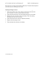
LIST OF EXPERIMENTS
1. Valve refacing and valve seat grinding and checking for
leakage of valves
2. Trouble shooting in cooling system of an automotive vehicle
3. Trouble shooting in the ignition system, setting of contact
breaker points and spark plug gap
4. Demonstration of sterring system and measurement of
steering geometry angles and their impact on vehicle
performance.
5. Trouble shooting in braking system with specific reference
to master cylinder, brake shoes, overhauling of system and the
adjusting of the system and its testing.
6. Fault diagnosis in transmission system including clutches, gear
box assembly and differential.
7. Replacing of ring and studying the method of replacing piston after
repair.
AUTOMOBILE ENGG.
KCT COLLEGE OF ENGG. & TECHNOLOGY
DEPPT. OF MECHANICAL
EXPERIMENT NO 1
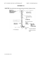
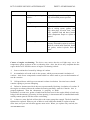
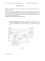
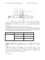
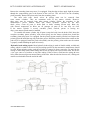
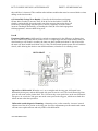
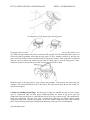
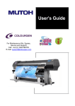
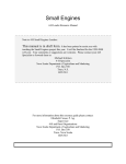
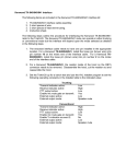
OBJECTIVE -Valve refacing and valve seat grinding and checking of leakage of valves
Do not remove
more than 0.010
mm
Check for bent stem
Diameter
0.79 Minimum
AUTOMOBILE ENGG.
Valve face
angle
This line should be
parallel with valve
head
KCT COLLEGE OF ENGG. & TECHNOLOGY
DEPPT. OF MECHANICAL
THEORY
•
Each cylinder has two valves, an intake and exhaust valve. Some high-performance
engines have four valves per cylinder- two intake and two exhaust valves. Usually, the intake
valve is larger than the exhaust valve. The reason is that when the intake valve is opened, the
only force moving air-fuel mixture into the cylinder is atmospheric pressure. When the exhaust
valve is opened, the piston is moving up, and there is a high pressure driving the exhaust
gases out. Therefore, the intake port must be larger to allow enough air-fuel mixture to enter.
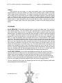
Various types of valves have been used in the past. But the valve in general use today is
mushroom, or poppet, valve. When the valve is closed, it is held on the valve seat by the valve
spring.
PROCEDURE
VALVE REFACING: If the valves are good enough to reuse, is to reface them. This requires a
valve-refacing machine. The valve refacer has a grinding wheel, a coolant delivery system,
and a chuck, which holds the valve for grinding. Set the chuck to grind the valve face at the
specified angle. This angle must just match the valve seat angle, or make an interference angle of
% to 1 degree. Then put the valve Into the chuck and tighten the chuck. The valve should be
placed in the chuck so that the part, of the stem that runs in the valve guide is gripped by the
chuck. To start the operation, align the coolant feed so that it sprays coolant on the rotating
valve face. Then start the machine. Move the lever to carry the valve face across the grinding
wheel. The first cut should be a light one. If this cut removes metal from only one-half or onethird of the face, the valve may not be centered in the chuck. Or the valve stem is bent, and the
valve should be discarded. Cuts after the first should remove only enough metal to true the
surface and remove pits. Do not take heavy cuts. If so much metal must be removed that the
margin is lost, discard the valve. Loss of the margin causes the valve to run hot. Then it will
soon fail. Follow the operating instructions of the valve-refacer manufacturer. Dress the grinding
wheel as necessary with the diamond-tipped dressing tool. As the tool is moved across the
rotating face of the grinding wheel, the diamond cleans and aligns the grinding face.
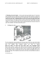
VALVE SEAT GRINDING:- For effective valve seating and sealing, the valve face must be
concentric with the valve stem. Also, the valve guide must be concentric with the valve face. In
addition, the valve face angle must match the valve seat angle (or have an interference
angle). Therefore, as a first step in valve seat service, the valve guides must be cleaned and
serviced. (Using a dial indicating valve guide gauge to check for wear . Movement of the probe
in and out of the guide will cause the needle to move if the guide is irregularly worn.)
The valve seats are of two types, the integral type and the insert type. Replacing seat inserts
and grinding seats are described below.
AUTOMOBILE ENGG.
KCT COLLEGE OF ENGG. & TECHNOLOGY
DEPPT. OF MECHANICAL
1. Replacing valve seat inserts: - A valve -seat insert may be badly worn. Or it may have
been refinished previously so that there is insufficient metal. With either condition, the seat must
be replaced the old seat must be removed with a special puller. If the puller is not available, the
insert is punch marked on two opposite sides. An electric drill is then used to drill holes almost
through the insert. Then, a chisel and hammer can be used to break the insert into two halves
so it can be removed. Care must be taken so that the counter bore isn't damaged. If the new
insert fits too loosely, the counter bore must be re-bored over size. Then an over size insert
installed. It may be necessary to chill the seat and heat the head before the seat is driven into
place. After installation, the valve seat should be ground
2.
Grinding valve seats: -
The valve seat grinder rotates a grinding stone of proper shape on the valve seat. A pilot installed
in the valve guide keeps the stone concentric with the valve seat. This means that the valve guide
must
be
cleaned
and
serviced
before
the
seat
is
ground.
In the seat grinder the stone is automatically lifted about once a revolution. This permits the
stone
to
clear
it
self
of
grit
and
dust
by
centrifugal
force.
After the seat is ground, it may too wide. Narrow the seat by using upper and lower grinding
stones to grind away the upper and lower edges of the seat. If the seat is too high, grinding with
the 150 stone may lower it. A steel scale can be used to measure seat width. When a new
valve is installed, it may sit too high above the seat. Then grind the seat slightly with a stone of
the same seat angle. This will lower the valve further into the seat, and raised the seat contact on
the valve face.
AUTOMOBILE ENGG.
KCT COLLEGE OF ENGG. & TECHNOLOGY
DEPPT. OF MECHANICAL
Many shops are now using a hand operated carbide cutter. This device takes the place of
motor driven stones in refinishing the valve seats.
Checking of leakage of valves:1.
Check valve guides for wear. Clean, replace or and ream for same size valve
stem if necessary. Or ream for a larger diameter valve stem.
2.
Check valves and valve seats. Clean valve heads and stems on a wire wheel.
3.
Refinish valve seats, and reface valves as necessary. Check valve seating.
Refinishing valve-stem ends if necessary.
4.
Check rocker arms for wear. Service or replace as necessary.
5.
Replace valves and springs in head.
6.
Check and adjust valve clearance as necessary.
AUTOMOBILE ENGG.
KCT COLLEGE OF ENGG. & TECHNOLOGY
DEPPT. OF MECHANICAL
EXPERIMENT NO 2
OBJECTIVE: -
Troubleshooting in cooling system of an automotive vehicle.
Theory: The purpose of cooling system is to keep the engine at its most efficient operating
temperature at all speeds & under all operating conditions. During the combustion of the air fuel
mixture in the engine cylinders, temperatures of 2200°C or higher may be reached by the burning
gases. The cylinder walls, cylinder head & pistons absorb some of this heat. They, in turn, must be
provided with some means of cooling so that they do not get hot.
Cylinder wall temperature must not go higher than about 205°C to 260°C Temperature higher than this
causes the lubricating oil film to break down & loose its lubricating properties. However, the engine
operates best at temperatures as close to the limits imposed by oil properties as possible. Removing too
much heat through cylinder walls & head lowers the thermal efficiency of the engine. Cooling
systems are designed to remove about one-third (30-35%) of the heat produced in the combustion
chambers by the burning of the air-fuel mixture The engine is very inefficient when cold. Therefore,
the cooling system includes devices that prevent normal cooling action during engine warm-up. These
devices allow the engine parts to reach their normal operating temperatures more quickly. This
shortens the inefficient cold operating time. When the engine reaches its normal operating
temperature, the cooling system begins to function. The cooling system removes excess heat when the
engine is hot & slowly or not at all when the engine is cold or warming up.
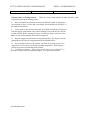
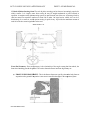
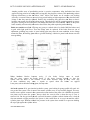
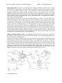
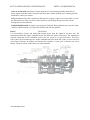
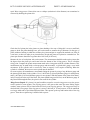
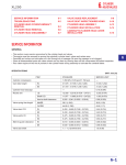
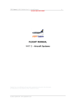
Cooling system
Main Parts of Cooling System: *
Radiator: It cools off coolant (it is an anti-freeze mixture) by allowing air passing through the area to
dissipate the heat generated by the engine.
Pump:
It draws the coolant from the radiator & pumps it through the engine block cylinder heads
heater core & back to the radiator.
AUTOMOBILE ENGG.
KCT COLLEGE OF ENGG. & TECHNOLOGY
DEPPT. OF MECHANICAL
Freeze plugs: It is actually a steel plug designed to seal holes in the engine block & cylinder head
created from the casting process. In freezing weather, they may push out if there is not enough antifreeze protection.
Head gasket: It seals the major parts of the engine to prevent oil, anti-freeze mixture and cylinder
pressure from mixing together.
Heater Core: It provides heat to the interior of the core by using heat removed from the anti-freeze &
flown in by the blower motor, may cause stead, odd or actual dripping inside the car when it leaks.
Thermostat: It controls the minimum operating temperature of the engine
The thermostat is closed when the engine is cold, in order to speed the warming-up & opens when
normal operating temperature has been reached, to allow the antifreeze to pass through the radiator.
Hoses:
These connect the other main components of the cooling system
Hose manufacturers recommend replacing every 4 years regardless of apparatus because there may be
deterioration of the inside of the hose which cannot be seen
Fan clutch: It senses the temperature of the air coming through the radiator & either slips or binds up
to the pull required amount of air through the radiator.
Electric cooling fan: Most front wheel cars use an electric cooling fan because of the transverse
mounted engine. It is turned on by a system of sensors & relays when the engine reaches about 230°F
& stays on until it is cooled to about 200°F.
Cooling System Trouble Diagnosis:
Three major cooling system complaints are:
• Loss of Coolant
• Engine overheating
• Slow warm up
Explanation:
Causes of loss of coolant: Many gaps can be spotted easily for two reasons One - the cooling
system requires frequent refilling. Two - the point of gap can be usually found at the top of a telltale
stain. Dye is added to most anti-freeze to make gap detection easier.
There are two types of coolant gaps. External gaps are those, where the coolant can drip into the
ground. These can be seen. Typical leak points from hose & hose connections, heater core, radiator core
& expansion core plugs (freeze plugs) in the block & head.
Internal leaks can severely damage the engine. The coolant may contaminate the oil & may cause
rust. A coolant leak into the combustion chamber while the engine is stopped may fill the combustion
chamber. If the leak is from the radiator, it should either be removed or replaced. Oil in the coolant
indicates leakage of transmission oil cooler in the outlet tank of the radiator. If the leak is at the hose
connections, the hose should be replaced.
AUTOMOBILE ENGG.
KCT COLLEGE OF ENGG. & TECHNOLOGY
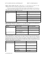
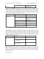
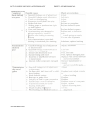
Condition
Loss of coolant
Possible cause
Pressure
defective
cap
DEPPT. OF MECHANICAL
Check or correction
and gasket Inspect. Wash gasket and test. Replace only
if cap will not hold pressure specified.
Leakage
Pressure test system
External leakage
Inspect hose, hose connections, radiator,
edges of cooling system, gaskets, core
plugs, drain plugs, oil-cooler lines, water
pump, expansion tank and hoses, heatersystem components. Repair or replace as
required
Internal leakage
Check torque of head bolts, retorque if
necessary. Disassembly engine as necessary.
Check for cracked intake manifold, blown
head gasket, cracked cylinder head or
engine
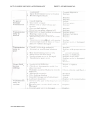
Causes of engine overheating: The driver may notice that the red light stays on or the
temperature gauge registers in the overheating zone. Also, the driver may complain that the
engine boiled over Possible causes of engine overheating include
1
Lower coolant level caused by leakage of coolant.
2
Accumulation of rust & scale in the system, which prevents normal circulation of
coolant. Anti-freeze compounds contain additives which tend to prevent theformation of
rust & corrosion
3. Collapsed hoses which prevent normal coolant circulation. Suction hoses should
contain a spring to prevent collapsing
4. Defective thermostat which does not open normally blocking circulation of coolant. If
the engine overheats without the radiator becoming normally, warm & if the fan belt is
properly tightened. Then the thermostat is properly at fault*
Sometimes, on some cars, grains of sand from the sand core for the engine block or head may
lodge in the thermostat, preventing it from opening. A thermostat that is installed backwards
usually cannot open & will also cause overheating.
5. A loose or worn fan belt will not drive the water pump fast enough. The belt should be
tightened or replaced. Where a pair of belts is used, both belts should be replaced at the
same time, not just one belt that appears most worn. When you replace only one belt, the
AUTOMOBILE ENGG.
KCT COLLEGE OF ENGG. & TECHNOLOGY
DEPPT. OF MECHANICAL
entire load is on new belt. It will wear rapidly. When both the belts are replaced with a none
matched pair, and then each belt will carry half the load.
6. Overheating may be caused by after boil. This may occur when the coolant starts
boil after the engine has been turned off. For example, after a long hard drive, engine has too
much heat in it, that when the water pump stops circulating coolant, it starts to boil.
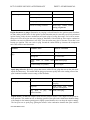
Condition
Possible cause
Engine
overheating
Low coolant level
Fill as required. Check for coolant loss.
loose fan belts Pressure cap
defective
Adjust Test. Replace if necessary.
Radiator
or
airconditioner condenser
obstructed Thermostat stuck
closed
Fan
drive
clutch
defective
Ignition faulty
Remove bugs, leaves, and debris. Test. Replace
if necessary..
Temperature gauge or HOT
light defective
Inadequate coolant flow
Exhaust system restricted
Check electric circuits. Repair as Required
Check or correction
Test. Replace if necessary
Check timing and advance. Adjust as required.
Check water pump and block for blockage
Check with restrictions
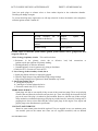
Causes of slow warm-up:
The most likely cause of slow warm-up is a
thermostat that is struck open. This allows the coolant to circulate between the engine & the radiator
even though the engine is cold. Therefore, the engine has to run longer to reach normal operating
temperature. As a result, engine wear is greater because the engine operates cold for a longer time.
Another possible cause of slow warm-up is that the thermostat has been removed. Never
remove the thermostat & leave it out of cooling system. This does not improve coolant circulation. It
does delay warm-up & increase engine wear & sludge formation.
A quick check for a missing or struck open thermostat can be made by squeezing the upper hose
immediately after starting the cold engine. Keep your hand away from the fan. No coolant flow through
the upper hose should be felt if you feel movement, the thermostat is missing or open
condition
Possible Causes
Check or Correction
Slow warm up
Open or missing thermostat
Test replace or install
necessary
AUTOMOBILE ENGG.
KCT COLLEGE OF ENGG. & TECHNOLOGY
Defective temperature gauge
DEPPT. OF MECHANICAL
Check electric Circuit
Working safely on Cooling System:
There are several safety hazards one must watch for, when
working on engine & the cooling system:
1.
Keep your hands away from the moving fan. When the engine is running, the
fan is turning so fast it is a blur. But it can mangle your hand and cut-off fingers, if
the hand gets into the fan.
2.
Never stand in a direct line with the fan. A fan blade could break off & fly out
from the engine compartment. Any person standing in line with the fan could be
injured or killed. Before starting the engine, examine the fan for cracked or loose
blades. If you find any damage the fan must be replaced.
3. Keep the fingers away from the moving belt & pulleys. The fingers could be
pinched & cut-off if they are caught between the belt and the pulley
4. Never attempt to remove the radiator cap from the cooling system of an
engine that is near or above its normal operating temperature. Releasing the
pressure may cause instant boiling of the coolant.
5.
Coolant is poisonous:- It can cause serious illness or even death if it is
swallowed. Always wash your hands thoroughly, if you get coolant on them.
AUTOMOBILE ENGG.
KCT COLLEGE OF ENGG. & TECHNOLOGY
DEPPT. OF MECHANICAL
EXPERIMENT NO 3
OBJECTIVE:
Trouble shooting in the ignition system, setting of contact breaker points and spark plug gap
THEORY:
The basic difference between the contact-point and the electronic ignition systems is in the
primary circuit. The primary circuit on the contact-point system is opened and closed by contact
points. In the electronic system, the primary circuit is opened and closed by the electronic control
unit (ECU).
The secondary circuits are practically the same for the two systems. The difference is that
the distributor, ignition coil, and the wiring are altered to handle the higher voltage that the
electronic ignition system produces.
One advantage of this higher voltage -upto-47,000 volts- is that spark plugs with wider gaps
can be used. This results in a longer spark which can ignite leaner air-fuel mixtures. As a result,
engines can run on leaner air-fuel mixtures for better fuel economy and lower emissions.
Another difference is that some electronic ignition systems have no mechanical advantage
mechanisms -centrifugal or vacuum. Instead, the spark timing is adjusted electronically.
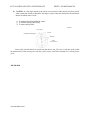
DIAGRAM:
Trouble shooting in ignition system
Ignition- system quick check: Several checks have been used in the past to help locate the cause of
various troubles for e.g. one test is the spark test. Remove a cable from spark plug, insert plug
extender into the cable end, and hold the extender into about 3/8" (10mm) from the engine block with
insulated pliers. Crank the engine and check for sparking. If no sparking occurs, there is trouble in the
ignition system. If there is good spark, the failure to start is probably in the fuel system. This test is
not recommended for all electronic ignition systems.
AUTOMOBILE ENGG.
KCT COLLEGE OF ENGG. & TECHNOLOGY
DEPPT. OF MECHANICAL
Engine cranks normally but fails to start: There is no spark during the spark test, if the
oscilloscope fails to show a secondary voltage pattern there are several possible causes:
If you get a good spark, the ignition primary and secondary circuits probably are ok. The failure to
start could be due to fouled spark plugs or out of time ignition. However failure to start with a good
spark is more likely due to trouble in the fuel system.
Condition
Possible Causes
Check or correction
Engine cranks normally but No voltage to ignition system
fails to start
ECU ground lead open, loose
or corroded
Ignition coil open or shorted
Check
battery,
wiring
Repair as needed
ignition switch,
Test coil, replace if defective.
ECU faulty
Replace
Damaged armature or sensor
Replace damaged part
Defective distributor cap or Replace defective part
rotor
Engine backfires but fails to start: This can be caused by ignition or valve timing that is
considerably off by faulty or wet distributor cup or rotor that allows high voltage leakage from one
terminal to another or by high voltage cables being incorrectly connected .
Condition
Possible Causes
Incorrect timing
Check or correction
Check and adjust timing
Moisture in distributor cap
Dry cap
Cap faulty- voltage leakage Replace cap
across carbon paths
cables
not Reconnect cables correctly
Engine backfires but fails to High voltage
connected in firing order
start
Engine runs but misses: An engine that runs misses runs unevenly and does not develop full power. It is
some time difficult to tell by listening whether one cylinder is missing or whether the miss is intermittent
and jumping around from one cylinder to another if one cylinder is missing the cause could be a defective
spark plug or high voltage cable, a bad connection, and high voltage leakage across the distributor cap or
through the cable insulation. In the engine the miss could be due to struck or burned valves or loss of
compression resulting from broken piston rings
Condition
Possible Causes
Check or correction
Engine runs but misses
Spark plug s faulty
Clean and regap, or replace
High voltage cables defective
Replace
Defective coil or distributor cap Replace
or rotor faulty
Bad connection
AUTOMOBILE ENGG.
Clean, tighten
•
KCT COLLEGE OF ENGG. & TECHNOLOGY
DEPPT. OF MECHANICAL
Advance mechanism defective
Check advances , repair or
replace distributor
Engine runs but backfires: Backfiring is a pop or bang in the exhaust manifold. It can be
caused by several conditions in the ignition system. If the ignition timing is considerably off or if
ignition crosses firing occurs, ignition may result before the intake valve closes. This produces a
backfire. There will be a pop back through the air cleaner. Cross firing is spark jump over from one
terminal to another, or from one high voltage cable to cracked or damaged cable insulation can allow
spark jump over. Incorrect fuel ratio can also cause backfire.
Condition
Engine
runs
back fires:
Possible Causes
but Ignition timing off
Check or correction
Retime
Ignition cross firing
Check high voltage cables,
distributor’ cap and rotor for
leakage, path
Faulty ant backfire valve
Replace valve
Spark plugs of wrong heat Install correct plugs
range
Defective air-injection system Check system
Fuel
system
not Check carburetor
supplying proper air fuel ratio
Engine overheats: Most engine overheating is caused by loss of coolant through leaks in cooling
system. Other causes include a loose or broken fan belt, a defective water pump, clogged water jacket in
the engine, a defective radiator hose, and a defective thermostat or fan clutch. Late ignition or valve
timing, lack of engine oil* over loading the engine, or high speed, high altitude or hot climate
operation can cause engine overheating. Freezing of coolant can cause lack of coolant circulation,
resulting in local hot spots and boiling.
Possible Causes
Condition
Check or correction
Engine overheats
Late Ignition timing
Retime
Lack of coolant or other trouble Fill the coolant.
in cooling system
Late valve timing
engine conditions
or other Adjust for best performance.
Engine lacks power: Many conditions can cause the engine to loose power. The wrong ignition
timing, or any of the conditions discussed in 4th point which cause the engine to miss, will reduce engine
power. As, a restricted exhaust system can create excessive backpressure, which will prevent normal
exhaust from the engine. The cylinders will retain the pressure and will not take in a full air fuel charge
during the intake strokes.
AUTOMOBILE ENGG.
KCT COLLEGE OF ENGG. & TECHNOLOGY
DEPPT. OF MECHANICAL
Condition
Possible Causes
Check or correction
Engine lack power
Ignition timing off
Retime
Exhaust system restricted
Clear
Heavy engine oil
Use correct viscosity oil
Excessive rolling resistance
Check tires, brakes, wheel
bearing, alignments
.
Engine detonates or pings: Detonation or pinging is often blamed on the ignition system. But there
are many other possible causes. In the ignition system detonation may be caused by excessively advanced
ignition timing, faulty advance mechanisms and spark plugs of wrong heat range. Fuel with an octane
rating too low for the engine can cause pinging or detonation. Carbon build up in the engine combustion
chambers can result in detonation in two ways. First the carbon may glow or become so hot that it can
become pre ignition. This can result in ping. Second the carbon builds up increases the compression
ratio. This can also cause detonation.
Condition
Engine
pings
Possible Causes
detonation
Check or correction
or Improper timing
Time ignition
Wrong fuel
*
Use correct fuel
Spark plugs of wrong
range
Carbon buildup in cylinders
heat Install correct plugs
Service engine
Spark plug defective: Basically, plugs that run too cold will foul, plug that run too hot with wear
rapidly and burn away. This means that the plug gap increases rapidly due to the eroding effect of the
spark combined with the excessive temp, of the electrodes.
Condition
Possible Causes
Spark plug defective
Cracked insulator
Check or correction
Plug sooty
Plug white or
blistered insulator
grey,
Careless installation, install
new plug.
Install hotter plug, control
high fuel consumption.
with Install cooler plug.
Engine diesels, or runs on: Engines with emission control require a fairly high hot idle speed for
best operation. This makes run on, or dieseling, possible. Hot spots in the combustion chambers along
with enough air fuel mixture getting past a slightly opened throttle valve can keep the engine running.
The hot spots act as spark plug, igniting the mixture in the combustion chamber hot spots could be
AUTOMOBILE ENGG.
KCT COLLEGE OF ENGG. & TECHNOLOGY
DEPPT. OF MECHANICAL
from, hot spark plugs or exhaust valves or from carbon deposits in the combustion chamber.
Dieseling can damage an engine.
To prevent dieseling many engines have an idle stop solenoid. It closes the throttle valve completely
when the ignition switch is turned off.
Condition
Possible Causes
Engine diesel, or run on
Idle-stop solenoid out
adjustment or defective
Hot spots in
chamber
Advance timing
Check or correction
of Readjust
necessary
,
replace
as
combustion Service engine
Retime ignition
Possible causes of electronic system failure, ignition system failures can be grouped into three
categories. These are
1.Loss of energy in primary circuit: This could result from:
a. Resistance in the primary circuit due to defective
ignition switch, open ignition coil primary winding.
b. Discharged battery or defective alternator.
c. Grounded primary circuit in ignition coil, wiring or distributor.
d. Defective ECU or sensor coil circuit to ECU.
2. Loss of energy in the secondary circuit, due to
lead,
bad
connections
or
a. Spark plug fouled, defective or improperly gapped.
b. Defective high voltage wiring which allows high voltage leakage.
c. High voltage leakage across ignition coil head, distributor cap or rotor.
3. Out of time ignition, due to:
a. Timing not set properly.
b. Centrifugal or vacuum advance defective.
c. Electronic control unit {ECU} defective.
SPARK PLUG SERVICE
Spark plugs will foul or wear rapidly if they are not of the correct heat range. There are spark plug
cleaners that sand blast the electrodes and porcelain tip. Then, after filling the electrodes flat, the
gap can be reset if the plug is in otherwise good condition. However, with the cost of labor so high,
many mechanics recommend replacing spark plugs at periodic intervals, instead of cleaning and regapping them. Always select and install the correct spark plugs for the engine. First, inspect and
gap the plugs to the manufacturer's specification.
CONTACT-POINT SERVICE
Burned or worn contact points should be replaced. They are supplied in sets; one stationary point,
one movable point on the contact arm. Some sets are supplied assembled, with an attached
AUTOMOBILE ENGG.
KCT COLLEGE OF ENGG. & TECHNOLOGY
DEPPT. OF MECHANICAL
condenser. Adjustment is made by turning an eccentric or by moving the stationary contact-point
support.
AUTOMOBILE ENGG.
KCT COLLEGE OF ENGG. & TECHNOLOGY
DEPPT. OF MECHANICAL
EXPERIMENT NO 4
Objective:- Demonstration of steering system by measurement of steering Geometry angles & their impact
on vehicle performance.
Theory The steering system allows the driver to guide the car along the road & turn left or right as
desired. The system included the steering wheel, which the driver controls, the steering gear, which the driver
change the rotary motion of the wheel into straight-line motion & the steering linkages. Most systems were
manual until a few years ago. Then power steering became popular. It is now installed on about 90 percent of
cars manufactured in the United State today.
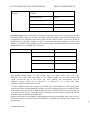
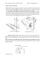
Demonstration of steering system: Types of Steering System:
i)
Pitman-arm steering gears: Steering linkage using pitman arms are shown. The steering or
at the lower end of the steering shaft consists essentially of two sports. These are a worm on the
end of the steering shaft & a pitman arm shaft on which there is a gear seek a toothed roller & a
stud
Front of Car
AUTOMOBILE ENGG.
KCT COLLEGE OF ENGG. & TECHNOLOGY
DEPPT. OF MECHANICAL
ii) Rack & Pinion Steering Gear: The rack & pinion steering gear has become increasingly popular for
today's smaller. It is simpler, more direct acting & may be straight mechanical or power assisted in
operation. A complete rack & pinion steering system, set apart from the rest of the cars. As steering wheel by
shaft are turned are turned the rack moves front side to other. On large heavier vehicle, this can be a
disadvantage. In a small car, rack & pinion steering is quick & easy. It provides the maximum amount of
road feel as the tires meet irregularities in the road.
Front of the Car
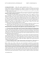
Front End Geometry: Front end geometry is the relationship of the angles among the front wheels, the
front wheel attaching parts & the ground. The various factors that enter into front & geometry are:
a) FRONT SUSPENSION HEIGHT - This is the distance from some specific point on the body, frame or
suspension to the ground. If suspension is not correct it can affect the angles in the suspension system
AUTOMOBILE ENGG.
KCT COLLEGE OF ENGG. & TECHNOLOGY
DEPPT. OF MECHANICAL
b) CAMBER - Camber is the belting in or out of the front wheels from the vertical when viewed from the front of
the vehicle. If the top of the wheels tilts out, it has positive chamber and if the top of the wheel tilts in, it has
negative angle.
Centre line
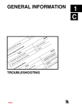
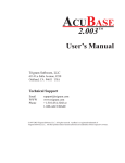
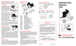
c) STEERING AXIS INCLINATION - It is also called ball joint inclination on vehicle that have
vertical & a line drawn through the centers of the wall joints, when viewed from the front of the
vehicle. Included angle= Camber + SAI.
Camber Angle
Steering Axis
Inclination
Steering Axis Inclination
Included angle
Ball joint
AUTOMOBILE ENGG.
KCT COLLEGE OF ENGG. & TECHNOLOGY
d)
DEPPT. OF MECHANICAL
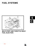
CASTER - It is the angle formed by the forced or rear ward tilt of the steering axis from vertical,
when viewed from the side of the wheel. The angle is positive when the steering axis tilts backwards.
Reason for which, caster is used:\
1. To maintain directional stability & control.
2. To increase steering return ability.
3. To reduce steering effort..
Vertical
Caster angle
Centre line of steering axis
Vertical
Ball Joint
Front of the Car
Caster of the left-front wheel as viewed from the driver's seat. The view is from the inside so that
the backward tilt of the steering axis from the vertical can be seen This backward tilt, is called positive
caster.
IDLER ARM
AUTOMOBILE ENGG.
KCT COLLEGE OF ENGG. & TECHNOLOGY
DEPPT. OF MECHANICAL
e) TOE - It is the amount in inches, millimeters or degrees in which the front wheels point
inward or outward. Its purpose is to stabilize steering & to prevent side- slipping & successive
wear of the tyres.
Toe-in. The wheels are viewed from above, with he front of the car at the lop of the illustration
distance A is less than distance B.
f)TURNING RADIUS - It is sometimes called toe-out during turns and turning angle. It is the
difference between the two angles formed by the two front wheels and the car during turn.
AUTOMOBILE ENGG.
KCT COLLEGE OF ENGG. & TECHNOLOGY
DEPPT. OF MECHANICAL
CENTER
Turning radius, or toe-out on turns
g) STEERING RATIO - Out of the jobs of steering gear is to provide mechanical
advantages. In a machine or mechanical device, this is the force supplied to it. The
steering ratio is the number of degrees that the steering wheels must be turned to pivot
the front wheels. Actual steering ratio varies, greatly, depending on the type of
operation. Steering ratio called fast or quick steering, require much less Steering heel
movement to produce the desired steering effort. Steering ratio is determined by two
factors. Steering linkage ratio & the gear ratio of the steering effort. In a rack & pinion
steering system, the steering ratio is determined, largely by the diameter of the pinion
gear. The smaller the pinion the higher the steering ratio. However there is a limit to
how small the pinion can be made.
AUTOMOBILE ENGG.
KCT COLLEGE OF ENGG. & TECHNOLOGY
DEPPT. OF MECHANICAL
EXPERIMENT NO 5
Objective-Trouble shooting in braking system with specific reference to master
cylinder, brake shoes, overhauling of system and the adjusting of the system and its
testing
Theory
The construction and operation of the various types of braking system used in automotive vehicles.
The braking system used most frequently operates hydraulically, by pressure applied through a
liquid. These are the foot-operated brakes that the driver normally uses to slow or stop the car. They are
called the service brakes. In addition, all cars have a parking-brake system, which is mechanically
operated by a separate foot or hand lever. On some trucks and busest the braking system is operated by air
pressure. This type of brake is an air brake.
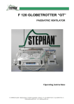
Diagram
Fluid Reservoir
Wheel
Cylinder
Wheel
Cylinder
Wheel
cylinder
Rear
Brake
DRUM BRAKE TROUBLE DIAGNOSIS
Brake pedal goes to the floor: When the brake pedal goes to the floor, there is no pedal reserve. Full
pedal travel does not produce adequate braking. One section might fail, but it would be rare for both to
fail at the same time. It is possible that the driver has continued to operate the vehicle with one section
out (either the driver may have ignored the warning light, or the pressure differential valve or the light
may have failed). Causes worn linings, air in the of failure could be linkage or brake shoes out of
adjustment, 3 system, lack of brake fluid, or a defective master cylinder
Complaint
AUTOMOBILE ENGG.
Possible Cause
Check or Correction
KCT COLLEGE OF ENGG. & TECHNOLOGY
Brake pedal
floorboard
goes
to Linkage
or
adjustment
shoes
DEPPT. OF MECHANICAL
out of Adjust
Brake linings worn
Replace
Lack of brake fluid
Add fluid; bleed system
I Air in system
Add fluid; bleed system
Worn master cylinder
Repair
One brake drags: If one brake drags, this means that the brake shoes are not moving away from the
brake drum when the brakes are released. This trouble could be caused by incorrect shoe adjustment, or by
a clogged brake line, which does not release pressure from the wheel cylinder. It could also be due to
sticking pistons in the wheel cylinder, to weak or broken brake-shoe return springs, or to loose wheel
bearings. Loose wheel bearings could permit the wheel to wobble so that the brake drum comes in contact
with the brake shoes even though they are retracted
Complaint
Possible Cause
Check or Correction
One brake drags
Shoes out of adjustment
Adjust
Clogged brake line
Clear or Replace line
Wheel cylinder defective
Repair or replace
Weak or broken return spring Replace
Loose wheel bearing
Adjust bearing
All brakes drag: When all the brakes drag, the brake pedal may not have
sufficient free travel. Then the pistons in the master cylinder do not fully retract. This
would prevent the lip of the piston cup from clearing the compensating port &
hydraulic pressure would not be relieved, as it should be. As a result, the wheel
cylinders would not allow the shoes to retract.
A similar condition could result if engine oil was added to the system. Engine oil- will cause the piston
cups to swell. If they swelled enough, they would not clear the compensating ports even with the piston
in the "fully retracted” position. A clogged compensating port would have the same result. Do not use a
wire or drill to clear the port. This might produce a burr that would cut the piston cup. Instead, the port
should be cleared with alcohol & compressed air.
Clogging of the reservoir vent might also cause dragging brakes by pressurizing the fluid in the reservoir.
This prevents release of pressure on the fluid in the lines. A clogged vent could also cause leakage of air
into the system
AUTOMOBILE ENGG.
KCT COLLEGE OF ENGG. & TECHNOLOGY
DEPPT. OF MECHANICAL
Complaint
Possible causes
Check or correction
All brake drags
Incorrect linkage adjustment
Adjust
Trouble in master cylinder
Mineral oil in system
Repair or replace
Replace damaged parts
Car pulls to one side: If the car pulls to one side when the brakes are applied, more braking force is
being applied on one side than to the other. In a front engine rear wheel drive car, linings will become
soaked with oil if the lubrication level in the rear axle is too high this may cause leakage past the oil seal.
At the front wheels, brake linings may get grease on them. If the front wheel bearings are over lubricated
or if the grease seal is defective or improperly installed. Wheel cylinder will leak brake fluid onto the
brake linings, if the cups are defective, if the cylinder bore is pitted, or if an activating pin has been
improperly installed. If the linings at the left wheel become soaked with brake fluid or oil, the car pulls
to the left because the brakes are more effective on the car's left side. However, the direction of pull may
depend on the type of friction material & the contaminant.
Complaint
Possible causes
Check or correction
Car pull to one side
Brake line clogged
Clear or replace line
Defective -wheel cylinder
Repair or replace
Brake
Tighten
backing plate loose
Mismatched linings
Use same linings all around
Soft or Spongy pedal: If the pedal action is soft or spongy, there is, probably, air in the hydraulic
system. Out of adjustment brake shoes could also cause this. Conditions that could allow air to enter the
hydraulic system are described
Complaint
Possible Cause
Check or Correction
Softy or spongy pedal
Air in system
Add
Brake
shoes
adjustment
out
brake fluid;
bleed system
of Adjust
Poor braking action (requiring excessive pedal force): A need for excessive pedal force could be
caused by improper brake shoe adjustment. The use of wrong brake lining could cause the same trouble.
Sometimes", brake linings that have become wet after a hard rain or after driving through water will not
provide sufficient friction against the drums. However, normal braking action is usually restored after the
brake linings have dried.
AUTOMOBILE ENGG.
KCT COLLEGE OF ENGG. & TECHNOLOGY
DEPPT. OF MECHANICAL
Another possible cause of poor braking action is excessive temperature. After the brakes have been
applied for long period as in coming down on long hill, they begin to overheat. This overheating reduces
braking effectiveness so that the brakes "fade". Often if the brakes are all owed to cool, braking
efficiency is restored. However,excessive long period braking at high temperature. May char the brake
linings so that they must be replaced. Further, this overheating may glaze this rake drum so that it
becomes too smooth for effective braking action. Then the drum must be ground or turned to remove
the glaze. Glazing can also take place even though the brakes are not overheated. Failure of the power
brake assembly will noticeably increase the force on the foot pedal required to produce braking.
Brake too sensitive or Grab: If linings are greasy or soaked with oil or brake fluid, the brakes tend
to grab with slight pedal force. Then the linings must be replaced. If the brake shoes are out of
adjustment, grabbing may result. A loose braking plate may cause the same condition. As the linings
contact the drum, the backing plate shifts to give hard braking. A defective power brake booster can also
cause grabbing.
Noisy brakes: Brakes become noisy, if the brake linings wear so much
that the rivets contact the brake drum, if the shoes become warped so that the
contact with the drum is not uniform, if the drum becomes rough & noisy worn. Any
of these conditions may cause a squeak or squeal when the brakes are applied
Loose parts, such as the brake backing plate, also may rattle.
Air in the system: If air gets into the hydraulic system, poor braking & spongy pedal will result. Air
can get into the system if the air vent in the master cylinder cover or cap becomes plugged. This may
tend to create a partial vacuum in the system on the return stroke of the piston. Air could then by-pass the
rear piston cup & enters the system. Always check the vent & clean it when the cap or cover is
removed. Air can also get into hydraulic system if the master cylinder residual checks valve is leaky &
does not maintain a slight pressure in the system. A leak could allow air to seep in around the wheelcylinder piston cups. Without residual line pressure in the system there would be no pressure holding
the cups tight against the cylinder valves.
AUTOMOBILE ENGG.
KCT COLLEGE OF ENGG. & TECHNOLOGY
DEPPT. OF MECHANICAL
Probably, the most common cause of air in the brake system is
insufficient brake fluid in the master cylinder, if the brake fluid drops below the
compensating port, the hydraulic system will draw air in as the piston moves forward
when braking Air in the system must be removed by adding brake fluid & bleeding
the system. ____
Loss of brake fluid: Brake fluid can be lost if master cylinder leaks, if the
wheel cylinder leaks, if the line connections are loose, if the line is damaged. One possible cause of the
wheel cylinder leakage or there is incorrect installation of actuating pin. If the pin is cocked, the side
thrust on the piston may permit leakage past the piston. Leakage from other causes at the master cylinder
or wheel cylinder requires removal & repair or replacement of the defective parts.
Complaint
Possible Cause
Check or Correction
Loss of brake fluid
Master cylinder leaks
Repair or replace
Wheel cylinder leaks
Repair or replace
Loose connection, damaged Tighten connections; replace
tube
tube
Brakes do not self-adjust:Brakes do not self adjust if the self-adjusted mechanism has been
removed,
or
if
the
adjustment
screw
is
stuck,
or
if
the
adjustment lever does not engage the star wheel, or if the adjuster was incorrectly
installed.
Warning light comes on when braking: If the warning light comes on when
braking, it means that there is low pressure in one section of the hydraulic system.
One of the two braking sections has failed. Both sections should be checked so that
the trouble can be found & eliminated. It is dangerous to drive in this condition Even
though the car slows, only half the wheels are being braked.
AUTOMOBILE ENGG.
KCT COLLEGE OF ENGG. & TECHNOLOGY
DEPPT. OF MECHANICAL
BRAKE TESTING & SERVICE
Brake testers: There are two types of brake testers - the static & the dynamic. One type of static
tester has four tread plates & registering columns. To make the tests, the car is driven onto the tread
plates at a specified speed & the brakes are applied hard. The stopping force at each wheel is registered
on the four columns. -If the readings are too low or are unequal, brake service is needed.
The dynamic brake tester has rollers in the floor. The two wheels, whose brakes are to be tested,
are placed on the rollers. If these are the drive wheels, the wheels are spun at the specified speed by the
vehicle engine, or otherwise, the wheels are spun by an electric motor. Then the throttle is released or
the electric motor is turned off and the brakes are applied. The braking force at each wheel registers
on meters. This shows if the brakes perform normally or if they need service.
Platform type brake tester
Dynamic Brake Tester
Replacing drum brake shoes: When linings wear, the brake shoes must be replaced. To
replace the shoe in a drum brake, the wheel & brake drum must be removed. Then shoes with new
linings are installed. Although been a practice years ago, brake shoes are relined at few locations even
todav.
ntil a few years ago, most relined shoes were "arced". This meant the shoes were ground slightly to better
fit the larger diameter of a used or refinished brake drum. However, grinding brake shoe is no longer
universally recommended. This is because of the hazards, resulting from the asbestos dust created
during shoe grinding.
ADJUSTER
SCREW
RETURN SPRING
AUTOMOBILE ENGG.
KCT COLLEGE OF ENGG. & TECHNOLOGY
DEPPT. OF MECHANICAL
Servicing brake & drums:
Brake disk requires replacement only if they
become deeply scored or are wrapped out of line. Light scores or grooving are normal & will not affect
braking. Some manufacturers recommend never grinding or refacing a scored brake disk. Instead,
installation of a new disk is recommended. Refer to the manufacturer's service manual for the proper
procedure to follow & tools to use.
Brake disks have a discard dimension (a number) cast into them. This dimension is the minimum
thickness to which the disk can be refinished. If the disk must be refinished to a thinner diameter,
discard it. The disk is too thin for safe use
On drum brakes, the drum should be inspected for distortion, cracks, scores, roughness or excessive
glaze or smoothness. Glaze lowers friction & braking* efficiency. Drums that are distorted or cracked
should be discarded & new drums installed. Light score marks can be removed with fine emery cloth.
All traces of emery must be removed after smoothing the drum. Deeper scores, roughness & glaze can
be removed by turning or grinding the drum. Many brake drums have their discard diameter cast into
them. This dimension is the maximum allowable diameter If it is necessary to turn or grind the drum to a
larger diameter, discard it. The drum would be too thin for safe use. Brake drums should not be
refinished to larger than the original diameter by more than 0.060" (1.5mm). This leaves 0.030"
(0.76mm) left for wear before the discard diameter is reached.
The diameters of left & right drums on the same axle should be within 0.010" (0.25mm) of each
other. When the drum diameters on the same axle vary more, than this, replace both drums.
Wheel cylinder service: Most wheel cylinders can be disassembled & rebuilt on the car. However,
many manufacturers recommend that the wheel cylinder be removed from the backing plate & serviced on
the bench. This makes it easier to properly & thoroughly clean, inspect & reassemble the cylinder.
To remove a wheel cylinder from the car, first remove the wheel & brake drum. Then disconnect the
brake hose or tube from the wheel cylinder. Remove the wheel cylinder by taking out the attachment bolts
or retainer. Then tape the end of the hose or pipe shut to prevent any dirt from getting in. Disassemble the
wheel cylinder by first pulling off the boots. Then push out the piston cups & springs. Clean all wheel
cylinder pats in clean brake fluid. Dry the parts with compressed air. Then place the dried parts on clean lint
free shop towels or paper. Check that all passages in the wheel cylinder & bleeder screws are clear by
blowing through them with compressed air.
Inspect the cylinder bore for scoring & corrosion. Use crocus cloth to remove light corrosion & strains.
Replace the wheel cylinder if crocus cloth does not remove the corrosion, or if the bore is pitted or scored.
Some manufacturers permit the use of brake cylinder hone to remove scores & rust. However, the cylinder
bore must not be honed more than 0.003" (0.08mm) larger than its original diameter. If the scores do not
clean out, replace the cylinder. The wheel cylinder also should be replaced if the clearance between the
cylinders bore & the piston is excessive.
When reassembling the wheel, cylinder, lubricate all parts with clean brake oil. Then assemble the
wheel cylinder, using all parts in the repair kit. Install the bleeder screw & torque it to specifications.
Master cylinder service: Master cylinder may require disassembly for replacement of internal parts.
However, some technicians prefer to install a new or rebuilt cylinder. The service procedures for master
cylinder used with disk brakes & drum brakes are very similar. One difference is that with disk brakes a larger
brake fluid reservoir is required. With a braking system that has front wheel disk brakes & rear wheel drum
brakes. Note that the fluid reservoir for the front disk brakes is larger than the other. To service the master
cylinder, clean the outside. Then remove the master cylinder from the car. If the car has a manual brake
system, slide the boot to the rear, remove the retainer clip & then remove the retainer, push rod & boot. Use
the push rod to force the primary piston inward & remove the snap ring from the groove in the piston bore.
Then remove the primary piston assembly. The repair kit contains a complete new primary piston assembly.
AUTOMOBILE ENGG.
KCT COLLEGE OF ENGG. & TECHNOLOGY
DEPPT. OF MECHANICAL
Remove the secondary piston stop screw, if so equipped. Using the shop air hose apply slight air pressure
through the compensating port at the bottom of the reservoir. This will force out the secondary
piston assembly. Remove the piston seals from the secondary piston
The outer tube seats, check valves & springs must not be removed from
some master cylinders. They are permanent parts of the master cylinder. However,
these parts may be removed from other master cylinder. Follow the procedure in the
manufacturer's service manual. Most disk brakes hydraulic systems do not have
check valves. Clean all parts in brake fluid or brake cleaning solvent only. Blow dry
with filtered compressed air Blow out all passages & ports to be sure they are clear
If the master cylinder is scored, corroded, pitted, cracked, porous or scoring are
deep; a new master cylinder must be installed.
•
To assemble the master cylinder, dip all parts (except the body) into the brake fluid. Insert the
complete secondary piston assembly, with return spring, into the master cylinder bore. Install the
secondary piston stop screw if so equipped. Put the primary piston assembly into the bore Depress the
primary piston & install the snap ring in the bore groove. Install the push rod, boot & the retainer on the
push rod, if so equipped. Install the push rod assembly into the primary piston make sure the retainer
is properly seated & holding the push rod securely
Hydraulic brake tubing repair: Most hydraulic brake tubing is made of double-walled, welded steel
tubing, which is coated to resist rust. Only the tubing specified by the automotive manufacturer should
be used. When replacing a tube, used the old tube as a pattern to form a new tube. Do not kink the
tubing or make sharp bends. Brake tubing must be cut off square with a special tube cutter. Do not use
a jaw type cutter or a hacksaw to cut brake tubing. Either of these can distort the tubing & leave
heavy burns that would prevent normal flaring of the tube. After the tube has been cut off, a flaring tool
must be used to double flare the end of the tube.
AUTOMOBILE ENGG.
KCT COLLEGE OF ENGG. & TECHNOLOGY
DEPPT. OF MECHANICAL
Flushing Hydraulic: The process of removing all the old brake fluid from hydraulic system is called
flushing. Some car manufacturers recommend flushing the hydraulic system when new parts are installed
in it. The system must be flushed if there is any indication of brake fluid contamination. Signs of
dontaminated brake fluid include corroded metal parts and soft or swollen rubber parts. To flush the
hydraulic system installs the pressure bleeder on the master cylinder. If the car has metering valve, it must
be held in the open position Place the brake bleeder wrench on the bleeder valve in the wheel cylinder or
caliper nearest the master cylinder Install one e/id of a short bleeder hose on the bleeder valve Place the
other end in a transparent container.
Open the bleeder valve about 1 V4 turns & let the fluid drain into the container. Close the bleeder valve
when the fluid appears clean & clear Then move on to the bleeder valve next closest to the master
cylinder Repeat the procedure at each wheel When flushing is completed, check that the master cylinder
is filled. About 1 quart (0.946L) of clean, fresh brake fluid is needed to flush the hydraulic system If the
hydraulic system is being flushed because of fluid contamination, replace all rubber parts in the master
cylinder wheel cylinders & calipers, brake hoses & combination valve Then bleed the hydraulic system.
Some manufacturers recommend the use of special flushing fluid. This fluid \s used instead of new brake
fluid during the flushing operation. Flushing is continued until all the old brake fluid has been flushed out.
Then the flushing fluid is purged by applying clean dry air through the master cylinder to blow the fluid
out. Do not use too much air pressure. After all flushing fluid is out. fill the master cylinder reservoir with
new brake fluid. Then bleed the system as explained below
Filling & bleeding hydraulic system: After flushing the hydraulic system or at any time, air may be in
the hydraulic system. The hydraulic system must be filled and bled. For the brakes to operate properly all
air must be removed from the system.
The process of getting rid of any air trapped into the system line or component is called bleeding. In the
bleeding process, brake fluid is forced through the brake line or component that has air in it. To bleed the
brakes, install the pressure bleeder on the master cylinder. If the vehicle has a metering valve, it must be
held in the open position Place the bleeder wrench on the bleeder valve in the wheel cylinder or caliper
nearest the master cylinder. Install one end of the bleeder hose on the bleeder valve. The lower end of the
bleeder hose is immersed in clear container partly filled with fresh brake fluid. This allows you to see any
air bubbles that come out of the line it also prevents any air from being pulled back into the line. This can
happen if the pressure on the brake fluid is released before the bleeder valve is closed.
AUTOMOBILE ENGG.
KCT COLLEGE OF ENGG. & TECHNOLOGY
DEPPT. OF MECHANICAL
If the master cylinder has bleeder valve and open it about % turn Watch the flow of brake fluid from the
end of the hose. As soon as the bubbles stop & brake fluid flows from the hose in a solid stream, close the
bleeder valve. Repeat these steps at each wheel. Then disconnect the pressure bleeder from the master
cylinder. Check that the master cylinder is filled with brake fluid. Wipe up any spilled brake fluid. Install
the master cylinder. Cover the seal & cover. Pump the brake pedal several times. Be sure that the firm
brake pedal is obtained before moving the vehicle.
AUTOMOBILE ENGG.
KCT COLLEGE OF ENGG. & TECHNOLOGY
DEPPT. OF MECHANICAL
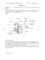
EXPERIMENT NO 6
OBJECTIVE:
differential.
Fault diagnosis in transmission system including clutches, gear box assembly &
Purpose of clutches: The clutch is used in cars with transmission that are shifted by hand. It
allows the drive to couple/uncouple the engine from the, transmission. Power flows from the engine,
through the clutch, to the transmission & power train.
Diagram
Pressure Plate
Pivot
Pressure spring
Throwout Bearing
Fly wheel
Linkage
Disk
Pivot
Disk
Clutch Pedal
Clutch fork
Friction
Friction
Release lever
Weight
Splines on
transmission input
shaft
FAULT DIAGNOSIS1) Clutch slips while engaged: The slipping clutch generates excessive heat & may burns causes
may be incorrectly linkage of pedal. Readjusting the linkage may correct the problem. Binding linkage
or a broken return spring may prevent full return of the linkage to the engaged position. If none of the
above is causing the slippage then remove the clutch for service.
The recommendation of most manufacturers is it replaces the disk & pressure plate assembly if there is
internal wear or 'damage or weak springs. Pressure plate assemblies can be rebuilt, but this usually is a
job for clutch rebuilder.
AUTOMOBILE ENGG.
KCT COLLEGE OF ENGG. & TECHNOLOGY
DEPPT. OF MECHANICAL
2) Clutch chatters or Grabs when Engaged- Check the clutch linkage for binding It is binds could
release suddenly to throw the clutch into quick engagement with a resulting heavy jerk. A broken engine
mount can also cause chattering because the engine is free to move excessively. Inside the clutch, the
trouble could be due to oil or grease on the disk facings or to glazed or loose facings
Complaint
Clutch chatters or grabs
when engaged
Possible Cause
Oil or grease on disk
facings or glazed or loose
facings
Binding of friction-disk hub
on clutch shaft
Check or correction
Replace facings or disks
Binding in clutch-release
Linkage
Free,
adjust,
lubricate
Broken engine mount
Warped clutch disk
Replace
Replace
Clean
and
lubricate
Splines replace defective
parts
and
3)
Clutch spins or drags when disengaged- The first check is pedal linkages adjustment if there is
excessive pedal lash or free travel, even full movement of the pedal will not release the clutch faulty.
One cause of loose friction disk facings is abuse of the clutch. This abuse includes "popping" the
clutch for a quick gateway (letting the clutch out suddenly with the engine turning at high rpm)
slipping the, clutch for drag strip starts & modifying the engine for increased power output
Complaint
Clutch spins or drags
when disengaged
Possible Cause
Possible Cause
pedal-linkage
Incorrect adjustment
Check or correction
Readjust
Wrapped friction disk or
pressure plate
Loose friction-disk facing
Broken engine mount
Replace defective parts
Improper
adjustment
Readjust
release-lever
Replace, defective parts
4) Clutch Noise- It is noticeable when the engine is idling. Noise is heard when the clutch is either
engaged or disengaged or during pedal movement. Noises heard while the pedal is in motion are
probably due to dry/dirty linkage pivot points. Noise heard when the transmission is in neutral but
disappear when the pedal is depressed are transmission noises. Noise heard while the clutch is
engaged could be due to a friction on disk hub i.e. loose on clutch shaft or perhaps both it both are
excessively worn.
5) Clutch Pedal Pulsates- Noticeable when a slight force is applied to the clutch pedal with the
engine running. Pulsations can be felt by the foot as a series of slight pedal movements & ceases when
AUTOMOBILE ENGG.
KCT COLLEGE OF ENGG. & TECHNOLOGY
DEPPT. OF MECHANICAL
the pedal force is increased. This condition often indicates troubles that must be corrected before serious
damage to the clutch results.
6) Friction Disk Facings Wear Rapidly- Caused by the friction between slippage
facings & the flywheel or pressure plate. If the driver has the habit of "riding" the
clutch by resting the left foot on the pedal, part of the pressure plate spring force will
be taken up so that slippage may take place. Likewise, frequently use of the clutch,
incorrect clutching & declutching, overloading the clutch, & slow clutch engagement
& disengagements increase dutch facing wear
Part B
Function of differential A differential is required to compensate for the difference in distance that
the drive wheels travel when the car rounds a curve. If a right angle turn were made with the inner rear
wheel turning on a 20 foot(6.1 m) radius, the inner rear wheel would travel about 31 feet (9.5m) while
the outer rear wheel would travel about 39 fe^t (12m). The differential permits power flow to both drive
wheels, while allowing the wheels to turn different distance, when the car is rounding a curve.
DRTV6 SHAFT
--
Operation of differential: When the car is on a straight road, the ring gear, differential case,
differential pinion gears, and two differential side gears all turn as a unit. The two differential pinion
gears do not rotate on the pinion shaft. This is because they exert equal force on the two differential
side gears. As a result, the side gears turn at the same speed as the ring gear, which causes both drive
wheels to turn at the same speed also.
Differential trouble diagnosis- Humming: A humming noise is often caused by incorrect internal
adjustment of the drive pinion or the ring gear. Incorrect adjustments prevent normal tooth contact
and can cause rapid tooth wear and early failure of the differential.
AUTOMOBILE ENGG.
KCT COLLEGE OF ENGG. & TECHNOLOGY
DEPPT. OF MECHANICAL
Noise on acceleration: Noise that is louder when the car is accelerating probably means there is
heavy contact on the heel ends o f the gear teeth Noise that is louder when the car is coasting probably
means there is heavy toe contact.
Noise on curves: Noise that is heard only when the car is going a round a curve the trouble is inside
the differential case They can also be due to defective axle bearing. During a turn, the out side
bearing takes an increased load.
Limited slip differential: It requires a special type of lubricant. Wrong lubricant can cause the clutch
surfaces to grab Remedy is to replace the old lubricant with the right one.
Part-C
GEAR BOX
It is an assembly of gears and shafts that transmit power from the engine to the drive axle. The
transmission allows the engine crankshaft to turn fast while the wheels turn slowly. The transmission
can then change the ratio of crankshaft speed to the car speed as car speed increases. Therefore,
with a three-speed transmission, the engine crankshaft may turn about four, eight, or twelve times for
each wheel revolution. In addition, the transmission includes a reverse gear so that the car can be
backed. The driver selects each of these gear ratios manually
AUTOMOBILE ENGG.
KCT COLLEGE OF ENGG. & TECHNOLOGY
Fault diagnosis in gear box
AUTOMOBILE ENGG.
DEPPT. OF MECHANICAL
KCT COLLEGE OF ENGG. & TECHNOLOGY
AUTOMOBILE ENGG.
DEPPT. OF MECHANICAL
KCT COLLEGE OF ENGG. & TECHNOLOGY
AUTOMOBILE ENGG.
DEPPT. OF MECHANICAL
KCT COLLEGE OF ENGG. & TECHNOLOGY
DEPPT. OF MECHANICAL
EXPERIMENT NO 7
OBJECTIVE: - Replacing-of ring and studying the method of replacing piston after repair
Theory:-The pistons are slightly smaller; there is a gap, or clearance, between the piston and the cylinder.
This gap must be filled. Otherwise, some of the compressed air-fuel mixture would leak out through the
clearance. Also, when combustion took place, much of the high-pressure gas would leak out. These leaks
would greatly reduce the efficiency of the engine. Much of the power would be lost. To prevent this
piston rings are installed on the pistons.
Top compression Ring
Ring side
Steel
Expander
From a sliding seal between the piston and the cylinder wall. These are called
compression rings.
Scrape off most of the oil that is splashed on the wall so that it does not get up into the combustion
chamber where it would burn. These are called oil control rings
Piston Ring Service: When an engine is disassembled for service, the old piston rings should not be
reinstalled. Rings that have been used, even for very short time, usually will not reset properly. Selection
of new piston rings depends on the condition of the cylinder walls and how they are to be reconditioned.
If the cylinder walls are only slightly tapered or out of round, then the new standard rings selected for an
engine may depend on the cylinder reconditioning procedure that has been used.
Automotive manufacturers generally recommend refinishing the cylinder walls before piston ring
installation to "Break the Glaze". Cylinder walls take on a hard, smooth glaze after the engine has been
running. In many automotive shops, this glaze is removed by running a glaze breaker up and down the
cylinder a few times before installing new rings. The glaze is a good antis cuff surface and will not retard
the seating of certain type new rings. However, the cylinder walls must be reasonably round and in good
condition. When a cylinder is honed, the proper honing job leaves a Crosshatch pattern on the cylinder
AUTOMOBILE ENGG.
KCT COLLEGE OF ENGG. & TECHNOLOGY
DEPPT. OF MECHANICAL
walls. The hone marks should intersect at about a 60-degree angle. This leaves the surface needed for oil
retention and quick seating of new rings.
Fitting Piston Rings: Piston rings must be fitted to the cylinder and to the rings grooves in the piston.
Rings come in packaged sets in graduated sizes to fit various sizes of cylinders. Most packages include
instructions that describe how to install the rings. Follow these instructions carefully:
Pressure
Gauge
As a first step, the rings should be pushed down into the cylinder with a piston, and the ring gap
measured. The ring gap is the space between the ends of the rings. It is measured with a thickness gauge.
Figure shows the gap being measured with ring pushed down to the lower limit of ring travel. If the
cylinder is worn, that is where the ring gap will be smallest. If you may have the wrong ring set for the
engine, you may have incorrectly measured cylinder diameter, or the wrong rings may have been
packaged in the box. Typical piston ring end gap in an automotive engine is from 0. 010 to 0. 020 inch [0.
25 to 0. 51 mm].
If the cylinder is tapered, the diameter at the lower limit of the ring travel (in the cylinder) will be smaller
then the diameter at the top. Therefore, the ring must be fitted to the diameter at the lower limit of ring
travel. If it is fitted to the upper part of the cylinder, the ring gap will not be great enough at the lower
limit of the ring travel. As a result, the ring ends will touch together. The ring will be broken, and the
cylinder wall will be scored. Always measure the ring gap with ring pushed down to its minimum
diameter at the lower limit of ring travel. The clearance should be wide enough so that the ring ends do
not butt together at normal engine temperatures
AUTOMOBILE ENGG.
KCT COLLEGE OF ENGG. & TECHNOLOGY
DEPPT. OF MECHANICAL
Checking the lit oil the piston ring in the ring-groove
If ring gap correct, insert the outside surface of the ring into the proper ring groove in the piston (see in
fig). Then roll ring around in the groove to make sure the ring has a free fit around the entire piston. An
excessively tight fit probably means that the ring groove is dirty. Another possibility is that the ring
groove' has been nicked or burred with the blade of ring groove cleaner. Some companies recommend
using the end of a broken ring, which has been filed to a sharp edge to clean the ring grooves. Some
technicians prefer this because the piece of the ring will not cause nicks or burrs
Install the rings in the ring grooves, using a piston ring expander. Then measure the piston-ring side
clearance. The clearance should be least 0. 001 inch [0. 025 mm] and not more then 0. 004 inch [0. 10
mm] for most engines.
Cautions on installing Piston Rings: The three-part oil rings are installed one part at a time' various
types of compression rings and their proper installed positions are shown in fig. Never spiral the
compression rings into the grooves. (Spiraling the rails of an oil ring is shown in fig). This could bend or
break the compression ring and cause loss of compression and blow by. Instead, always install
compression rings with a piston-ring expander. Never over-expand compression rings while installing
them. They may break piston rings installed upside down may cause excessive oil consumption.
AUTOMOBILE ENGG.
KCT COLLEGE OF ENGG. & TECHNOLOGY
DEPPT. OF MECHANICAL
The piston rings must be fitted to the ring grooves in the piston and also to cylinder. If you are fitting
rings to a tapered cylinder, check the ring end gap at the lower limit of ring travel.
PISTON:Theory
Pistons are usually made of aluminum alloy, which is a mixture of aluminum and other metals.
Automotive pistons weigh about 1 pound (0.454 kg) they are a sliding fit in the cylinders. This means the
pistons can slide up and down in the cylinders. This means the pistons are slightly smaller in diameter
than the cylinders.
Diagram
Piston Service: After the piston and rod assemblies are removed from the engine, the pistons and rods
should be separated. Then the rings can be removed from the pistons. The rings can also be removed from
the pistons before the pistons and rods are separated. A piston-ring expander can be used for ring
removal. The tool has two small tangs that catch under the ends of ring. When force is applied to the tool
handles, the ring is opened slightly so it can be lifted out of the ring groove and off the piston. Install new
rings during an engine overhaul. Once the ring break-in coating and tool marks are worn off, the ring will
not reset itself if it is reinstalled.
Piston Cleaning: Remove carbon and varnish carefully from piston surfaces. Do not uses a caustic
cleaning solution or wire brush .These could damage the piston-skirt finish. You may decide to rein stall
the pistons in the engine. Therefore, do not damage them. Use the cleaning method provided in your shop
to clean the pistons. Clean rings grooves with a clean-out tool. You can also use the end of a broken
piston ring filed to a sharp edge. Oil-ring slots, or holes, must be clean so that oil can drain back from
them. Use a drill of the proper size. Do not remove the metal when cleaning the slots or holes.
Piston Inspection: Examine the pistons carefully for wear, scuffs, scored skirts, worn ring grooves, and
cracks. Look for cracks at the ring lands, skirts, pin bosses, and heads. Any defects require replacement of
the piston, with these exceptions: cutting the grooves larger and using ring-groove spacers can sometimes
AUTOMOBILE ENGG.
KCT COLLEGE OF ENGG. & TECHNOLOGY
DEPPT. OF MECHANICAL
repair Worn ring grooves. Piston-skirt wear or collapse (reduction in skirt diameter) can sometimes be
corrected by knurling the piston skirt.
Using a micrometer to measure piston diameter
Check the fit of piston pins in the pistons or piston bushings. One-way of doing this is to use a small-hole
gauge to check the piston-bushing bores, and a micrometer to measure the pin diameter. On the type of
piston without a bushing in which the oscillates, the piston and pin are supplied in matched sets. If the fit
is too loose, or there are other pin or piston defects, the pin and piston are replaced as a matched set. The
piston-pin clearance should be no greater then 0. 001 inch [0. 025 mm].
Measure the size of each piston with a micrometer. The measurement should be made on the piston skirt
90 degrees from the piston pin, and 6-mm below the bottom of the oil-ring groove. This is called the
sizing point. Compare the piston measurement made at the sizing point with the cylinder diameter. This
measurement may be made with a telescope gauge and micrometer, a cylinder-bore gauge, or an inside
micrometer. If the cylinder wall is excessively worn or tapered, it will require refinishing. When the
cylinder is refinished, then a new oversize piston must be installed.
On some engines, the manufacturer recommends fitting the pistons by using a long thickness gauge and
the piston (upside down) in the cylinder. Use a 0. 0025-inch [0. 06 mm] thickness gauge for used pistons,
and a 0. 002 inch [0. 05 mm] thickness gauge for new pistons. With the bottom of the piston skirt about 1
inch [25 mm] below the top of the block, the piston should hang (not fall free) on the thickness gauge. If
the piston falls through the bore, the piston is too small for the cylinder.
Ring-Groove Repair: If a piston is in good condition except for excessive ring groove wear, the groove
can be repaired in some pistons. The top ring groove is the groove that wears the most. During engine
overhaul, many pistons will be found with excessively worn top ring grooves. The ring groove may be
checked with a wear gauge. If the ring groove is worn 0. 006 inch [0. 15 mm] or more, it can be machined
to a larger width with a special hand-operated lathe. This squares up the top and bottom sides of the ring
groove. Then the new piston ring is installed with a spacer.
AUTOMOBILE ENGG.
KCT COLLEGE OF ENGG. & TECHNOLOGY
DEPPT. OF MECHANICAL
Piston Resizing: automotive manufacturers do not recommend Resizing of collapsed or worn pistons.
Excessive resizing can weaken the piston. One piston-reconditioning procedure for older piston is
knurling. The piston skirt is run between a supporting wheels and a knurling tool. This displaces metal,
which expands the diameter of the piston skirt. The indentations from little pockets that can hold
lubricating oil to reduce scuffing.
Selecting New Pistons: New pistons are ready for assembly and installation when they are removed from
the box. They are available in various sizes for each engine, usually known as "Standard Oversize". When
oversize pistons are used, the cylinders are rebored and then finished to fit the pistons. Engine
manufacturers supply oversize piston of the same weight as the original pistons. This eliminates any
balance problem with the engine when different size pistons are installed. Some engine repairs may
require the reboring of only one or two cylinders. When this is done, maximum cylinder-size difference
should not exceed 0. 010inch [0. 25 mm].
Aluminum pistons are usually supplied with new piston pins already fitted and packaged in the same box.
This ensures the proper clearance between the pin and the pin bore in the piston. New pistons have a
special finish to prevent scuffing during initial start-up. They must not be buffed with a wire wheel. This
would remove the finish and increase the chances of scuffing during break-in.
Fitting Piston Pins in Pistons: On pistons with piston-pin bushings, worn bushings may be replaced. The
new bushings are honed to size to fit the piston pins. Piston-pin clearance should be no greater then 0. 001
inch [0. 025 mm]. Aluminum pistons are supplied with prefitted piston pins as a matched set. If a pin set
is required. However, some automotive machine shops hone the piston-pin otherwise in good condition.
Most engine manufacturers do not recommend this.
Rod-And-Piston Alignment: After the rod and piston have been reassembled, but before the rings are
installed on the piston, alignment should be checked with a rod aligner. A V block is held against the
piston. If the V block does not line up with the faceplate as the piston is swung across it, the connecting
rod is bent or twisted. Some connecting rods can be straightened. Check with the manufacturer's service
manual before reusing a straightened connecting rod
AUTOMOBILE ENGG.