1
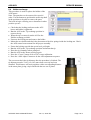
AGS-XXX SERVICE MANUAL dametric AGS Sensor SERVICE MANUAL AGS-XXX Service Manual EN.docx Jan. 17, 2012 / BL Page 1 of 9 AGS-XXX SERVICE MANUAL Content 1 General .......................................................................................................................... 2 2 Mounting / removal off the sensor .............................................................................. 3 3 House-to-holder coupling ............................................................................................ 4 3.1 AGS-XXX types ....................................................................................................... 4 3.2 AGS-XXXS types .................................................................................................... 4 4 Tip-to-house coupling .................................................................................................. 4 5 Tip service..................................................................................................................... 4 6 7 5.1 AGS-XP-XXX tips .................................................................................................... 5 5.2 AGS-XP-SXXX tips ................................................................................................. 5 AGS service from the Panel-PC .................................................................................. 5 6.1 Auto calibrate .......................................................................................................... 5 6.2 Coarse calibrate ...................................................................................................... 6 6.3 Tip replacement ...................................................................................................... 6 6.4 Holder exchange ..................................................................................................... 7 6.5 Flush position adjustment, version 1.5.x.x............................................................... 8 6.6 Flush position adjustment, version 2.x .................................................................... 9 Contact .......................................................................................................................... 9 1 General This service manual describes how service and to change the parts of the AGS-Sensor. The AGS (Adjustable Gap Sensor) is a gap sensor where the measuring tip can be moved axially. The movement of the tip enables a complete automatic calibration during full production in the refiner. The sensor is based on three main parts; a house, a holder and a measuring tip. The house includes a mechanical adjustment device, an electrical stepping motor, an axial position sensor and a sensor for the touch point vibration. The holder is a mechanical adaptor between the house and measuring tip to the mechanical dimensions of the TDC-hole in the refiner stator plate. The AGS sensor has the same mechanical dimensions in the tip end as the corresponding TDC-sensor so they are interchangeable. The tip is a wear part and will wear as the segment plates are worn down. It is replaced periodically by the mill service personnel. The tip is attached to the shaft of the house by a special bayonet coupling. This coupling uses a spring tensioning device to eliminate axial and radial play. The spring has to be released in order to separate the tip and for this we use an edge inside the holder. This means that the tip has to be removed first and then the holder. AGS-XXX Service Manual EN.docx Jan. 17, 2012 / BL Page 2 of 9 AGS-XXX SERVICE MANUAL The holder is mounted to the house by a nut which uses spring washers (AGS-XXX types) or ball bearings (AGS-SXXX types) to maintain axial zero play. The Tip Replacement and Holder exchange services are each driven by a sequence from the Panel PC which also instructs the user what to do. Therefore it is best if the electrical cable remains connected to the AGS sensor during the service work. Note that he house must never be rotated while mounted in the refiner. Instead turn the holder and hold the house still. 2 Mounting / removal off the sensor The sensor has to be removed from the refiner in order to replace the tip or if to change the holder. The electrical cables must remain connected since we need the sensor online when we do the service. It is not allowed to turn the AGS house when the sensor is mounted into a refiner. The internal TDC-connector will break if the house is turned and the sensor tip is jammed with the stator plates. Hold the house still and turn the brass holder with the special 40 mm tool until the sensor can be pulled out. When mounting the sensor, hold the house still and turn the holder until it hits the segment plate. DO NOT pull to tight; excessive force will damage the brass edge in the holder with the result that the sensor is not aligned with the stator plate. The tip will protrude into the refining zone which will give a lower gap reading than the true one. Then make sure that the nut of the holder is tightened to the sensor flange. Use the special tool and hold the sensor with your hand. AGS-XXX Service Manual EN.docx Jan. 17, 2012 / BL Page 3 of 9 AGS-XXX SERVICE MANUAL 3 House-to-holder coupling 3.1 AGS-XXX types The coupling between the house and the holder includes a locking nut (A), a flat washer (B) and a spring washer (D). Please notice the position of the spring washer. The coupling will give an axial play if not positioned correctly. Use the special tool to tighten the locking nut into the flange of the house. Check the position of the springs if the holder or the house is exchanged. 3.2 AGS-XXXS types The coupling between the house and the holder includes a locking nut (A), two ball bearings (B), shims (C) and a circlip (D). This solution ensures that the holder (D) can be rotated without loosening the locking nut (A). The locking nut is only loosened when the holder is changed. It is important that the locking nut is fully tightened; otherwise the axial play will result in a false gap reading. Use the special tool to tighten or loosen the locking nut. A B C A B C D 4 Tip-to-house coupling The coupling uses a special spring tensioning device to eliminate axial and radial play. The coupling is released during the tip replace routine by moving the tip shaft forward. An edge inside the holder will then release the spring so the user can replace the tip easily. This allows the tip to be changed within a minute without any special tools. The procedure is controlled by software; see the ‘TIP REPLACEMENT’ paragraph below. 5 Tip service The tip should be replaced when the plates are changed. This assures B that the tip length matches the plate thickness. If a new sensor is used again with new plates, it is essential that the tip is checked and serviced. It is extremely important that the mid pole “A” is not worn. This forms the measuring area and any wear in this area will immediately affect the gap value. The “B” indicates absolute maximum allowed wear limit. A Note. This is after the expected service life, which is when the tip is removed from the refiner. If the tip is worn beyond this point, the front piece will be loose and the gap signal is lost. The best case in this situation is that the refiner trips and stops but in worst case the segment plate’s clashes and the refiner might be damaged. AGS-XXX Service Manual EN.docx Jan. 17, 2012 / BL Page 4 of 9 AGS-XXX SERVICE MANUAL 5.1 AGS-XP-XXX tips Clean the tip with a cloth to remove grease and dirt. Check that the id number can be read (this number must be entered to the computer later). Grease the area in the picture with high temperature (> 250°C or > 480°F) silicon grease. 5.2 AGS-XP-SXXX tips Check the O-ring on the back edge of the sleeve. Grease with high temperature (> 250°C or > 480°F) silicon grease. Inspect the gasket inside the sleeve. If any irregularities, replace the whole tip (the gasket cannot be changed). 6 AGS service from the Panel-PC Go to the AGS Service form the Menu form: AGS Auto Calibrate Used for AGS calibration. Coarse Calibrate Used for AGS coarse calibration. Tip Replacement The function for tip replacement is reached here. Holder Exchange Use this function to exchange the holder. Adjust Flush pos. The tip can be aligned with the stator plates (not shown for all sensor types). The Tip Replacement and Holder Exchange functions are available first after you have logged in with the service code in the Menu form. 6.1 Auto calibrate Here you can calibrate the AGS sensors which are done with automation. Consult the “GmsCeAgs-Calibration_Eng.pdf” or the “GmsCe20Ags Calibration EN.pdf” manuals for details. AGS-XXX Service Manual EN.docx Jan. 17, 2012 / BL Page 5 of 9 AGS-XXX SERVICE MANUAL 6.2 Coarse calibrate Coarse calibration is performed when a new tip is mounted. Consult the “GmsCeAgs-Calibration_Eng.pdf” or the “GmsCe20Ags Calibration EN.pdf” manuals for details The Tip Replacement and Holder Exchange functions are available first after you have logged in with the service code in the Menu form. 6.3 Tip replacement When the tip is worn out, you use this sequence driven function to change to a new tip. Press the Start button to start the sequence. The progress of the sequence is shown in the yellow window. During the sequence you will be prompted to pull out the tip and then put in a new one. Please note the id number of the new tip because this shall be entered before the new tip is inserted. If something should go wrong it is possible to stop the sequence at any time by pressing the Halt button. Please check the tip distance after the procedure is finished. The tip distance must be 23.00 (+0/-0.05) mm when a new tip has been installed. This distance will work together with a corresponding distance in the stator plate giving a tip in flush with the new set of plates. This is the sequence order. Check that the locking nut between the AGS house and holder is tightened. Start with the ‘Start’ button. The tip is moved forward about 18 mm. Remove the tip by pulling it straight out. Feed the tip identification number into the system. Mount the new tip. Retract the new tip by moving the tip 18 mm backwards to the home pos. The system will perform a coarse calibration (3.80mm). The system will perform an APO adjustment. Check the 23.00 mm distance according to the figure above. The sequence is automatic but the user must confirm every step by pushing the ’Next’ button. AGS-XXX Service Manual EN.docx Jan. 17, 2012 / BL Page 6 of 9 AGS-XXX SERVICE MANUAL 6.4 Holder exchange This procedure is used to replace the holder of the AGS sensor. Note. The parts have to be removed in a special order. Use the buttons to position the sensor tip shaft in the positions to be able to remove the parts. The built in logic will help you to determine in what position you are. Check that the locking nut between the AGS house and holder is tightened. Run the AGS to the 'Tip exchange position' to remove the tip. When the tip is removed, run the AGS to the 'Holder exchange position'. Unscrew the locking nut and remove the holder. Mount the new holder and check the placement of the disc springs inside the locking nut. Check the AGS sensor house manual for the proper assembly. Fasten the locking nut with the special tool, pull tight. Run the AGS to the 'Tip exchange position' and mount the tip. Enter the tip id number when prompted. Run the AGS to the 'Home position' again. Press the “Coarse” button to do a TDC coarse calibration. Press the “APO Adjust” button to do the APO adjustment sequence. The user must check the tip distance after the procedure is finished. The tip distance must be 23.00 (+0/-0.05) mm when a new tip has been installed. This distance will work together with a corresponding distance in the stator plate giving a tip in flush with the new set of plates. AGS-XXX Service Manual EN.docx Jan. 17, 2012 / BL Page 7 of 9 AGS-XXX SERVICE MANUAL 6.5 Flush position adjustment, version 1.5.x.x For the Panel-PC software version 1.5.x.x. This procedure is only applicable to AGS sensor types without a fixed segment edge of 23.0 mm behind the wear plane. These sensors are valid for this procedure: AGS-SB170, AGS-TW60, AGS-HXD, AGS-LC72, AGS-LCL400. The purpose with this function is to align the AGS sensor tip to the wear plane of the stator plates. Use this after each plate change and tip change. The tip is first mechanically aligned within 0.20 mm end then electronically aligned to zero fault. Press the ‘Menu’ button on the Panel-PC, log in with the service-code, press the ‘AGS Service‘ button, press the ‘Adjust flush pos. ‘ button. Press the ‘Clear APO’ button to remove previous offset adjustment Press the ‘To APO=0‘ button to move the tip to the home position (APO = 0.00). This will move the tip slightly (normally less than 0.25mm). Mount the AGS sensor and align the tip within 0.2mm with the wear surface of the plates. Tighten the locking nut of the AGS sensor. Use the ‘Move tip‘ buttons to align the sensor with the plates. The TED function can be used (if activated) to measure the alignment by placing a steel ruler on the plates. The TED-value will reach 100% when the tip touches the ruler. Then, back off another 0.02mm from this position. Without the TED, use a ruler and a feeler gauge to measure the alignment. The Tip movement can be changed with the +/- buttons When the tip is fully aligned, press the 'Set APO to Flush’ button. Close the window and log out. AGS-XXX Service Manual EN.docx Jan. 17, 2012 / BL Page 8 of 9 AGS-XXX SERVICE MANUAL 6.6 Flush position adjustment, version 2.x For the Panel-PC software version 2.x.x.x. This procedure is only applicable to AGS sensor types without a fixed segment edge of 23.0 mm behind the wear plane. These sensors are valid for this procedure: AGS-SB170, AGS-TW60, AGS-HXD, AGSLC72, AGS-LCL400. The purpose with this function is to align the AGS sensor tip to the wear plane of the stator plates. Use this after each plate change and tip change. The tip is first mechanically aligned within 0.20 mm end then electronically aligned to zero fault. Press the ‘Menu’ button on the Panel-PC, log in with the service-code, press the ‘AGS Service‘ button, press the ‘Adjust flush pos. ‘ button. Press the ‘Clear APO’ button to remove previous offset adjustment Press the ‘To APO=0‘ button to move the tip to the home position (APO = 0.00). This will move the tip slightly (normally less than 0.25mm). Mount the AGS sensor and align the tip within 0.2mm with the wear surface of the plates. Tighten the locking nut of the AGS sensor. Use the ‘Move tip‘ buttons to align the sensor with the plates. The TED function can be used (if activated) to measure the alignment by placing a steel ruler on the plates. The TED-value will reach 100% when the tip touches the ruler. Then, back off another 0.02mm from this position. Without the TED, use a ruler and a feeler gauge to measure the alignment. The Tip movement can be changed with the +/- buttons When the tip is fully aligned, press the 'Set APO to Flush’ button. Close the window and log out. 7 Contact Development, production and service: Dametric AB Jägerhorns Väg 19, SE-141 75 Kungens Kurva, Sweden Phone: +46-8 556 477 00 Telefax: +46-8 556 477 29 e-mail: [email protected] www.dametric.se dametric AGS-XXX Service Manual EN.docx Jan. 17, 2012 / BL Page 9 of 9