1
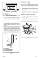
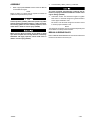
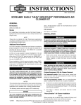
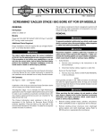
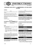
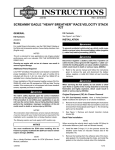
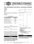
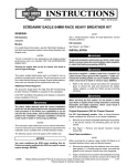
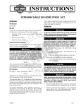
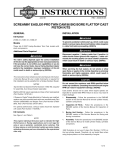
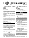
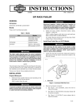
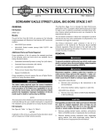
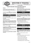
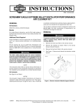
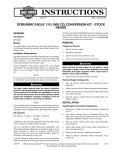
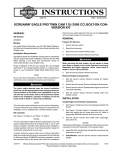
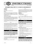
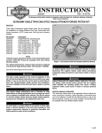
-J03624
REV. 2007-01-10
XL 1200 CC HIGH COMPRESSION PISTON KITS
GENERAL
Kit Number
22711-04, 22712-04, and 22713-04
Models
For model fitment information, please see the P&A Retail Catalog or the Parts and Accessories section of www.harleydavidson.com (English only).
Disconnect negative (-) battery cable first. If positive (+)
cable should contact ground with negative (-) cable connected, the resulting sparks can cause a battery explosion,
which could result in death or serious injury. (00049a)
1.
Disconnect battery cables, negative (-) cable first.
2.
Refer to appropriate ENGINE sections of Service Manual
to remove cylinder heads, cylinders, and pistons.
Additional Parts Required
Service Gasket Kit 17049-04A is required for assembly and
must be purchased separately.
INSPECTION
Piston Pin Retaining Ring Installer HD-34623-C is required for
assembly and must be purchased separately.
•
Check the head gasket and base gasket surfaces for flatness.
Carbureted models: Screamin' Eagle Pro Ignition Race Tuner
or Screamin' Eagle Pro Ignition Module is required and must
be purchased separately.
•
Remove burrs from all gasket surfaces.
EFI models: Screamin' Eagle Pro EFI Race Tuner is required
and must be purchased separately.
•
Check the clearance between the new piston pin and the
connecting rod bushing.
•
Replace the bushing if pin clearance is 0.002 in. or more.
After removing the cylinders:
Before installing the new pistons:
BORING AND HONING PROCEDURE
The rider's safety depends upon the correct installation
of this kit. Use the appropriate service manual procedures.
If the procedure is not within your capabilities or you do
not have the correct tools, have a Harley-Davidson dealer
perform the installation. Improper installation of this kit
could result in death or serious injury. (00333a)
1.
Check again for burrs on the cylinder gasket surfaces and
remove burrs before continuing to Step 2.
2.
Install the following components:
NOTE
This instruction sheet references Service Manual information.
A Service Manual for your model motorcycle is required for
this installation and is available from a Harley-Davidson dealer.
Kit Contents
See Figure 4 and Table 1.
NOTE
This engine related performance part is intended for High
Performance or Racing applications and is not legal for sale
or use on pollution controlled motor vehicles. This kit reduces
or voids the limited vehicle warranty. Engine related performance parts are intended for the experienced rider only.
DISASSEMBLY
3.
a.
Original head and base gaskets.
b.
Cylinder torque plates HD-33446-B.
c.
Evolution bolts and washers HD-33446-4.
Tighten the bolts. Refer to CYLINDER HEAD INSTALLATION section in Service Manual.
NOTE
Torque plates, properly tightened and installed with gaskets,
simulate engine operating conditions. Measurements vary as
much as 0.001 in. without torque plates.
4.
Bore the cylinder with gaskets and torque plates attached.
Bore the cylinder to 0.003 in. under the desired finished
size.
NOTE
Use the piston to determine finished size. Piston fit to the
cylinder must be within the range 0.0025 in. to 0.0035 in.
To prevent accidental vehicle start-up, which could cause
death or serious injury, disconnect battery cables (negative
(-) cable first) before proceeding. (00307a)
-J03624
1 of 4
PISTON INSTALLATION
is00120
NOTE
The 1200 cc pistons in this kit are coated with electroless nickel
coating. The pistons are directional and the arrow must point
forward.These pistons are not specific to front or back cylinders
and can be installed in either of the two cylinders.
2
1. Piston width
2. Measurement area
7.
2.
Install the piston rings with dots and bevels facing up.
Piston rings with no markings can be installed either side
up
PISTON PIN CIRCLIP INSTALLATION
Figure 1. Piston Measurements
6.
Check the piston rings for proper side clearance and end
gap. Refer to appropriate ENGINE sections in Service
Manual. The end gaps of adjacent rings must be installed
90 degrees apart.
2
1
5.
1.
See Figure 1. Measure the piston width (1), 90 degrees
horizontally from both sides of the pin piston pin hole and
at 1/2 in. above (2) the lowest portion of the skirt above
the chamfer.
Hone the cylinder to its finished size using a 280 grit rigid
hone followed by a 240 grit flexible ball hone. Honing must
be done with torque plates attached. All honing must be
done from the bottom (crankcase) end of the cylinder.
Maintain a 60 degree crosshatch pattern in the piston
travel area.
See Figure 2. After machining and honing, chamfer the
bottom inner edge (1) of the cylinder liner. The chamfer
provides a beveled surface for easier installation of the
cylinder over the piston rings. Break leading edge of liner
to a flat surface. The bottom edge of the liner (2) will be
somewhat sharp after machining. This sharp edge could
easily cause damage during installation of the cylinder.
is00123
1.
See Figure 3. Insert the circlip (4) onto the Piston Pin
Retaining Ring Installer.
2.
Squeeze handles of tool together and insert circlip into
slot of the piston. Release the handles and remove tool.
3.
Repeat steps for remaining circlips.
is00125
1
2
4
1. Piston pin lock ring
2. Piston pin retaining ring installer (HD-34623-C)
3
Figure 3. Seating Circlip
1
2
1.
2.
3.
4.
Inside chamfer
Cylinder liner bottom edge
Cylinder liner outside wall
Cylinder liner inside wall
Figure 2. Inside Chamfer and Bottom Edge of Cylinder
Liner
-J03624
2 of 4
ASSEMBLY
1.
2.
Connect battery cables, positive (+) cable first.
Refer to appropriate ENGINE sections of Service Manual
to assemble the engine.
NOTE
Engine re-jetting or re-timing may be required to achieve full
potential of this performance product.
You must recalibrate the ECM when installing this kit.
Failure to properly recalibrate the ECM can result in severe
engine damage. (00399b)
3.
Connect positive (+) battery cable first. If positive (+) cable
should contact ground with negative (-) cable connected,
the resulting sparks can cause a battery explosion, which
could result in death or serious injury. (00068a)
When servicing the fuel system, do not smoke or allow
open flame or sparks in the vicinity. Gasoline is extremely
flammable and highly explosive, which could result in
death or serious injury. (00330a)
-J03624
Carbureted models: Use Screamin' Eagle Pro Ignition
Race Turner or Screamin' Eagle Pro Ignition Module to
ensure proper installation of kit.
EFI models: Use Screamin' Eagle Pro EFI Race Turner
to ensure proper installation of kit.
NOTE
This diagnostic equipment must be purchased separately and
are available at a Harley-Davidson dealer.
BREAK-IN RIDING RULES
Refer to BREAK-IN RIDING RULES in the Owner's Manual for
instructions to break-in the motorcycle.
3 of 4
SERVICE PARTS
is04292
2
4
1
3
4
Figure 4. Service Parts: XL 1200 cc High Compression Piston Kits
Table 1. Service Parts: XL 1200 cc High Compression Piston Kits
Kit
Kit 22711-04
Standard
Kit 22712-04
+0.005 Inch
Kit 22713-04
+0.010 Inch
-J03624
Item
Description (Quantity)
Part Number
1
Piston, front and rear
Not Sold Separately
2
Piston Ring Set (2)
21925-04
3
Pin, piston (2)
22481-04
4
Circlip, piston pin (4)
22482-04
1
Piston, front and rear
Not Sold Separately
2
Piston Ring Set (2)
21926-04
3
Pin, piston (2)
22481-04
4
Circlip, piston pin (4)
22482-04
1
Piston, front and rear
Not Sold Separately
2
Piston Ring Set (2)
21927-04
3
Pin, piston (2)
22481-04
4
Circlip, piston pin (4)
22482-04
4 of 4