1
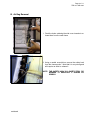
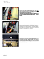
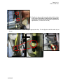
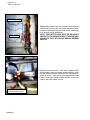
Page 1 of 11
Technical Service Bulletin
SUBJECT:
TSB−07−52B−003
No:
SEAT SIDE AIRBAG MODULE REPLACEMENT
November, 2007
DATE:
MODEL:
See Below
CIRCULATE TO:
[ ] GENERAL MANAGER
[X] PARTS MANAGER
[X] TECHNICIAN
[X] SERVICE ADVISOR
[X] SERVICE MANAGER
[X] WARRANTY PROCESSOR
[ ] SALES MANAGER
PURPOSE
Some affected vehicles may exhibit the “SRS” warning light illuminated on the instrument panel and DTC
B1421 Side Airbag Module (RH) (Squib) System Fault 2 or B1431 Side Airbag Module (LH) (Squib) System Fault 2 is recorded in the SRS ECU memory. If an affected vehicle has not been in a collision, and
normal diagnostic procedures confirm that the side air bag is malfunctioning and should be replaced, the
side air bag module can now be ordered and replaced separately. It is no longer necessary to replace
the seatback assembly.
AFFECTED VEHICLES
D
2006 − 2008 Eclipse
D
2007 − 2008 Eclipse Spyder
!
WARNING
S Never attempt to disassemble or repair the air bag modules. If faulty, replace the component.
S Do not drop the air bag modules or allow contact with water, grease, or oil. Replace the component if a dent, crack, deformation or rust is detected.
S Airbag modules should be stored on a flat surface with the pad cover facing upward. Do not
place anything on top of it.
S Do not expose the airbag modules to temperature over 93oC (200oF).
S Wear gloves and safety glasses when handling airbags that have been deployed.
S When removing and installing the front passenger seat, be sure to carry out the accuracy check
of the occupant classification sensor after the seat has been installed in the vehicle. Refer to
“Accuracy Check of the Occupant Classification Sensor” under “On Vehicle Service” in Group
52B Supplemental Restraint System − SRS
S Airbag modules must be properly disposed of. Refer to group 52B − Supplemental Restraint
System − SRS of the service manual for instructions relating to the proper disposal of airbags.
PROCEDURE
Using the scan tool in “ALL DTCs“ mode, scan the vehicle and record any DTCs that are displayed and
in which ECU they are displayed in. Conduct regular troubleshooting steps outlined in the service manual
for any DTCs and complete repairs for those faults (electrical connections, damaged wiring etc.) prior to
replacing any components.
Prior to starting repairs, record the customer’s radio presets and disconnect the negative (−) battery post.
Wait for a minimum of 60 seconds prior to making any disconnection of electrical connections related to
the SRS system. Refer to section 52B of the service manual for additional details on SRS Service
Precautions.
continued
FILE UNDER:
Group 52B Supplemental Restraint System in the Dealer Service Information Binder
(3186)
Page 2 of 11
TSB−07−52B−003
!
WARNING
DISCONNECT THE BATTERY AND WAIT 60 SECONDS PRIOR TO BEGINNING
WORK ON REMOVING THE SEAT.
A. Seat Removal and Disassembly
1. Refer to the the service manual, section 52A, and remove the applicable front seat from the vehicle.
Place the removed seat on a clean workbench covered with a shop blanket or equivalent protection.
Note: Plastic interior parts scratch easily. Protect the surrounding areas from damage when
removing the seat from the vehicle.
2. Remove the seatback panel to access the side air bag module connector and mounting nuts.
NOTE: It is not necessary to remove the bottom seat cushion.
D
Using a screw driver, probe behind the seatback panel and push the lower left and right side retaining
clips towards the center of the seat to release them from the panel. There is one on each side of the
seat.
Clip slides out of retainer.
3. Lift up on the bottom edge of the seat back panel and strike the panel along the centerline just below
the headrest opening as shown. This will release the upper retaining clips. Remove the seat back
panel.
Upper Seat Back Clips
4. Inspect all of the seat back clips for damage. Replace any damaged clips (part # 6979A005) and reinstall the lower clips to their mounting points on the seat back.
continued
Page 3 of 11
TSB−07−52B−003
B. Air Bag Removal
1. Push the hooks retaining the side cover inwards to release them from the seat frame.
2. Using a needle nosed pliers, remove the safety hook
from the frame anchor. Note that it is very strong and
will require an effort to release it.
NOTE: THE SAFETY HOOK IS A SAFETY ITEM. REMEMBER TO REINSTALL IT DURING ASSEMBLY.
continued
Page 4 of 11
TSB−07−52B−003
3. Remove the SRS module attaching nuts and retain
them for use with the new air bag module. Remove the
SRS module from the seat frame.
Take note of the harness routing for installation of
the new module.Eclipse Spyder Shown. Coupe
similar.
Eclipse Spyder
4. Using a needle nosed pliers, pull the black harness retaining clip out of the seat frame. On Eclipse Spyder,
locate the end of the white retaining clip and push it
through it’s mounting hole to release it.
Coupe & Spyder
CLIPS
5. Reposition the seat on the bench to allow access to the
underside of the seat. Release the two clips securing
the lower seat trim and fold the trim up and over the seat
back to allow access to the airbag wiring harness on the
underside of the seat.
continued
Page 5 of 11
TSB−07−52B−003
6. Locate the yellow harness on the underside of the seat assembly. Using pliers, remove the attachment
clips and cut the white tie wraps securing the harness together. The black tie at the bottom of the photo
can be detached and reused.
!
CAUTION
USE CARE WHEN CUTTING THE HARNESS FREE. DO NOT CUT THE AIRBAG
AND/OR SEAT BELT HARNESSES.
Driver’s Seat (LH)
Power Seat
Passenger ’s Seat
Manual Seat
All
CLIPS
CLIPS
CLIPS
TIE WRAPS
TIE WRAPS
TIE WRAPS
7. Reposition the seat and remove the airbag module from the seat frame.
NOTE: Take note of the harness routing for positioning the harness when installing the new
module.
!
WARNING
continued
AIRBAG MODULES MUST BE PROPERLY DISPOSED OF. REFER GROUP TO
52B SUPPLEMENTAL RESTRAINT SYSTEMS − SRS OF THE SERVICE MANUAL
FOR INSTRUCTIONS RELATING TO THE PROPER DISPOSAL OF AIRBAGS.
Page 6 of 11
TSB−07−52B−003
C. Airbag Module Installation
Install the new airbag module according to the following instructions.
!
CAUTION
Confirm that you have the airbag for the correct seat application. The first letter
of the serial number (L or R) relates to which seat the module is designed for.
“L” is for the left hand seat and “R” is for the right hand seat.
Route the airbag harness
through the opening in the
frame as shown.
1. Position the airbag between the seat cover and the
frame side rail. Loop the harness down the outside of
the frame and through the opening below the safety
hook as shown
CAUTION
THE AIRBAG MODULE MUST BE INSTALLED IN
THE PROPER DIRECTION, WITH THE HARNESS
PROTRUDING TOWARDS THE TOP OF THE SEAT
AND THEN LOOPING DOWN THE TO THE OPENING
IN THE FRAME SIDE RAIL.
2. Route the harness behind the cross brace and between
the inner plastic cover and the seat back assembly as
shown.
continued
Page 7 of 11
TSB−07−52B−003
3. Align the air bag module mounting studs with the holes
in the frame, hand start the fastener nuts retained during removal of the air bag and and then torque them to
specification. (4−6 Nm, 34−53 in lb)
4. Secure the harness to the frame using the appropriate clips. For the Spyder install the white clip as
shown.
Eclipse Spyder
continued
Coupe and Spyder
Page 8 of 11
TSB−07−52B−003
Seat Cover Hooks
Safety Hook
5. Reattach the safety hook, the 2 plastic hooks and the
4 black seat cover hooks to the seat frame as shown.
It may be necessary to tap the hooks with a rubber mallet to ensure proper attachment.
NOTE: THE SAFETY HOOK MUST BE SECURELY
SEATED TO ITS ANCHOR STRAP. IT MAY BE NECESSARY TO TAP IT INTO PLACE USING A RUBBER
MALLET.
6. Place the seat on its back. If the seat is equipped with
a seat heater, route the airbag module harness under
the seat heater harness and secure the harnesses together as shown. If the seat is not equipped with a seat
heater, secure the airbag module harness to the seat
cushion pan with a black tie clip.
Loop seat heater harness
around module harness.
continued
Page 9 of 11
TSB−07−52B−003
Connector
7. Secure the connector locating clip to the adjuster as
shown.
Secure clip to adjuster
8. Route the harness as shown.
!
CAUTION
Do not tie the seat power harness with the other harnesses.
NOTE:
DO NOT
TIE THE
POWER
SEAT
HARNESS.
CLIPS
CLIPS
Loop a white tie wrap
around the harnesses
as shown.
POWER SEAT (LH)
TIE WRAPS
MANUAL SEAT (LH)
TIE WRAPS
MANUAL SEAT (RH)
CLIPS
9. Wrap the bottom cloth around the seat and secure the
clips to the second seat cushion support wire.
continued
Page 10 of 11
TSB−07−52B−003
D. Seat Reassembly and Installation
10. Place the seat upright. Check the condition and location of the retaining clips. Secure the rear
cover to the back of the seatback.
11. Reinstall the seat into the vehicle, torquing all fasteners to spec. Refer to Group 52A − Interior, of the
service manual for details.
12. Insure all electrical connections are secure.
13. Reconnect the battery and reset radio memory.
14. Using the scan tool, conduct “Occupant Classification Accuracy Check” as per the service manual.
Refer to “Accuracy Check of the Occupant Classification Sensor” under “On Vehicle Service” in
Group 52B Supplemental Restraint System − SRS
15. Using the scan tool, perform Erase and Read All DTCs”. Diagnose and repair any DTCs that recur.
16. Test drive the vehicle to insure that no BSR or seat operation/adjustments have been created.
PARTS INFORMATION
Use the genuine Mitsubishi Part listed below.
!
CAUTION
Ordering and installing the correct (LH/RH) airbag module is crucial. Installing
the module to the incorrect seat will hamper inflation during impact.
Description
Part Number
Application/Comment
Side Airbag LH
MR306683
2006 − on Eclipse
Side Airbag RH
MR306684
2006 − on Eclipse
Side Airbag LH
MN121509
2007 − on Eclipse Spyder
Side Airbag RH
MN121510
2007 − on Eclipse Spyder
Hook, Frt. Seat
6979A005
Eclipse/Eclipse Spyder
Band, Frt. Seat White (Wire tie)
MR347763 (or equivalent)
As req’d
Band, Frt. Seat Black (Wire Tie)
MB953180 (or equivalent)
As req’d
continued
Page 11 of 11
TSB−07−52B−003
WARRANTY INFORMATION
This bulletin is supplied as technical information only and is not an authorization to repair.
If an affected vehicle is observed with the above condition, repair as described in this bulletin and submit
a normal warranty claim as follows.
Seat Air Bag Module Replacement
Nature Code: 260
Cause Code: 59D
Labor Operation No LH. 52113095
Time Allowance: 0.7 hr.
Labor Operation No. RH 52123095
Time Allowance: 0.7 hr.
Warranty Coverage:
Special Warranty Information:
Normal warranty procedures apply.
Warranty Coverage:
Restraint System Coverage Terms:
5 years/60,000 miles
Replaced Part Retention Requirements
Retain all warranty replaced air bag modules for a period of 5 days from the claim payment date. If requested, parts must be returned to the requested address adherent to hazardous material shipping requirements. See Section 10 of the Warranty Policy and Procedures Manual for Hazardous Materials
shipping information.
If not requested to be returned after 5 days from claim payment date have elapsed, warranty replaced
airbag modules may be properly disposed of locally. Refer to Section 52B − Supplemental Restraint
System (SRS), of the service manual for instructions relating to the proper disposal of airbags.
Mitsubishi Motors North America, Inc.
The information contained in this bulletin is subject to change. For the latest version of this document, go to the Mitsubishi Dealer Link, MEDIC,
or the Mitsubishi Service Information website (www.mitsubishitechinfo.com).