1
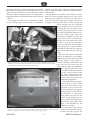
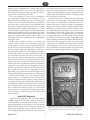
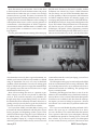
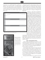
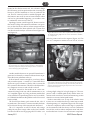
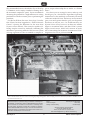
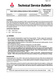
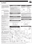
A service to members – $70 annually to subscribers © Mobile Air Conditioning Society Worldwide January 2011 By Dave Hobbs, MACS Technical Correspondent MASTERING HYBRID HVAC – TOYOTA PRIUS, PART 2 If you’ve made a New Year’s Resolution to increase profits at your shop by nding new repair opportunities, look no further than hybrids. It’s predicted that by the end of this decade, over 25 percent of all new vehicles produced will contain some type of hybrid electric technology. In the December 2010 MACS Service Reports, we took a dive into the HVAC system on the Toyota Prius line, along with a quick overview on how hybrid vehicles work in general. We also covered safety tips, electronic controls and the Gen II Prius electric compressor. This month, we’re going to dive in deeper. ‘till its clear” charge method will leave the system undercharged. The system charge is only 16 ounces nominally (Figure 1), which makes it a good candidate for charging with the newer and more accurate breed of J2788 R/R/R machines. Radically unique on the Gen II Prius is its coolant heat storage system (Figure 2). The system is an emissions reduction device that helps these cars achieve AT SULEV (Advanced Technology Super Ultra-Low Emission Vehicle) EPA status by lowering the hydrocarbon output on cold starts. The system works by recovering hot engine coolant, storing it in an insulated vacuum tank located in the LF inner fender area, and then pumping it into the en- 2004 – 2009 Generation II Prius – Peeking Under the Hood Let’s take a closer look under the hood starting, with the condenser. Gen II Prius condensers are multi-ow units with a modulator tank on the side that includes a typical Toyota-style replaceable drier/desiccant bag. The refrigerant passes through the modulator and desiccant before taking one last pass through the bottom portion of the condenser, which Toyota calls a sub-cooler. Even though the Prius sports an old fashioned sight glass, due to the condenser sub-cool cycle design, bubbles in the sight glass will disappear prior to the system being fully charged. This means a “add refrigerant and watch the sight glass Figure 2: In addition to a mechanical water pump on the front of the gas engine, there are two electric pumps for coolant – one for supplementing coolant ow for idle- stop heater performance (a), and the other for handling coolant in and out of the heat storage tank (b). Make sure you disconnect the grey connector from this pump prior to servicing the cooling system, to prevent hot coolant from being pumped out. A three way valve (c) handles management of coolant for either storage in the tank (d) or preheat of the engine. Figure 1: There’s no mistaking the correct oil type and charge amount for the Gen II Prius. Don’t use the sight glass while charging. With changing technology, it is more important than ever to follow OEM guidelines. MACS Service Reports is the official technical publication of the Mobile Air Conditioning Society Worldwide, Inc., P.O. Box 88, Lansdale, PA 19446. The material published in MACS Service Reports expresses the views of the contributors and not necessarily that of MACS. Every attempt has been made to ensure January 2011 the accuracy of the content of MACS Service Reports. MACS, however, will not be responsible for the accuracy of the information published nor will MACS Worldwide be liable in any way for injury, labor, parts or other expenses resulting from the use of information appearing in MACS Service Reports. 1 MACS Service Reports gine prior to the next cold start. You might not be able to hear the electric pump turn on while driving, but you will notice it turn on and run for a few seconds upon vehicle shut down. This is completely normal – the storage tank is being lled with hot coolant one last time prior to the next cold start. A few things you need to know about these systems. First, the storage tank’s location makes it vulnerable to damage, even after a minor collision. So keep that in mind when working on engine coolant leak complaints after a fender bender. Second, there is a potential for burns from hot coolant when the system is opened during service. Even several hours after you expect the coolant to be nice and cool, it is NOT. This tank will keep the coolant hot well past an overnight cold soak period. Plus, the electric pump that moves coolant in and out of the tank may run with the IP power switch off, so unplug the two wire electrical connector for this pump (which is located next to the storage tank) whenever servicing the cooling system. That said, the ECM may attempt to activate the pump while you have it disconnected, and that will cause either a DTC P1151 or P2601 to set. Be sure you clear those codes later. (While we’re on the subject of this pump, there is a Toyota bulletin, T-SB-0087-08 addressing an improved pump, should your customer’s become noisy.) Third, this tank contains coolant that needs to be included in your ushing procedures. The tank is the lowest point in the gas engine’s cooling system, so Figure 3: The view you are most likely to see from under the vehicle. The yellow petcock allows for traditional draining of the radiator and tank draining. A temp sensor helps the ECM determine outlet temperature when the pump is turned block won’t do. You need to open the on, and the control valve directs the coolant towards the engine. yellow petcock (Figure 3) in the bottom of the storage tank in order to do a complete ush and ll (unless you use a factory scan tool that can send a bi-directional command to the ECM to open up the system while you use your coolant ushing equipment). With all this hardware (pumps, control valves and hot coolant reservoirs), there is plenty of opportunity for an air lock when servicing a hybrid’s gas engine’s cooling system, so an Airlift tool is paramount in importance, along with a scan tool to run the electric coolant pump. Don’t forget to open the air bleed (Figure 4) in the top of the radiator (left side) as recommended by the OEM service manual. The mechanical water pumps Figure 4: With the plastic trim cover removed from the upper radiator support, you will nd a 6 mm hex tting in an air bleed valve in the top left of the radiator. Open this while running the electric pump with a on these cars are somewhat prone scan tool, to help purge the system of air when a coolant rell is being performed. to failure once they get past the January 2011 2 MACS Service Reports 100K mile point. I happened to be visiting a shop in Jackson Mississippi on a day when a tech was replacing one. The subject of coolant brand and type came up. Here we go again with a potential can of worms! If you can’t already tell, I favor factory recommendations, especially on things that are not old hat to me. Hybrids haven’t become old hat to me yet, so we had the parts chaser run to the local Toyota dealer to get the coolant they use. Guess what we were given? Universal Brand X coolant! I really wanted what the manual said to use. To quote the Toyota TIS (Technical Information System) – “Use only ‘TOYOTA Super Long Life Coolant’ or similar high quality ethylene glycol based non-silicate, non-amine, non-nitrite, and non-borate coolant with long-life hybrid organic acid technology. Coolant with long-life hybrid organic acid technology consists of a combination of low phosphates and organic acids.” The key words would be “long life,” “non-silicate” and “HOAT” (hybrid organic acid technology). Using the wrong coolant can, at the very least, reduce that long coolant service life we expect these days, not to mention present the potential for long-term degradation of cooling system components. Heater cores, for example, have tubes so thin that high mineral tap water or high silicate antifreeze can cause leaks down the road. Since the same type of Toyota coolant is used to cool the hybrid power electronics (inverters and converters), it would be good to use exactly what Toyota says to use. After all, the jury has not yet returned on the effects of alternative coolants on these major components, hoses and seals. Considering the price for an inverter/converter (not hundreds but thousands of dollars), wouldn’t it be nice to have a couple gallons of “the right stuff” on your parts shelf, to feed the engine cooling system AND the hybrid power electronics cooling system? One more thing, while we’re on the subject of hybrid cooling systems – it’s important to note that the hoses, coolant and pumps for the gas engine cooling system are very similar looking to the cooling system components for the hybrid power electronics. Be careful not to confuse the two. The bottom portion of the Gen II Prius radiator contains a separate (and isolated) section to cool the hybrid power electronics. The petcock for draining engine coolant (also yellow) is located just above this section of the engine’s radiator. two) with a meter between chassis ground and an orange cable. This voltage is limited to extremely low current, and is there strictly for diagnostic purposes (much like the low current that’s always present to ensure an airbag is properly connected in a SIR circuit). As mentioned in Part 1 of this report, the proper high voltage power down procedure, along with leak checked Class 0/1000 volt rubber gloves (with leather covers to protect them) and a Category III/1000 volt multimeter (Figure 5) are mandatory when working on hybrids. Make sure that not only is your meter rated for hybrids, but that your leads and probes are as well. If you encounter a DTC that indicates a leaky high voltage cable or component (such as the electric A/C compressor) you may not be able to visually determine where the problem is. The leak may be a pinhole size intrusion in a high voltage cable. Unlike leaky spark plug wires that can be tested with a ne mist of water while power braking the engine, you can’t do such a stress test with a hybrid’s high voltage cables. With the system properly powered down you can, however, connect a special meter (sometimes called a mega ohm meter) between an insulated terminal and chassis ground. Hybrid HVAC Diagnostics A general note on diagnostics with any hybrid – neither the high voltage DC nor the high voltage AC systems use a chassis ground, or common/neutral circuit, as we nd in typical automotive 12-volt systems or 115/230 volt residential electrical system. All HV circuits are isolated from chassis ground, although you may measure around ½ of the total high voltage in the vehicle (201 volts divided by January 2011 Figure 5: Not only is the Fluke 1587 multimeter a Category III/1000 volt meter suitable for hybrids, it also has a insulation test feature for detecting high resistance leaks in the insulation of cables or components. 3 MACS Service Reports Most ohm meters put out between .5 and 2 volts when in their resistance test mode. Insulation testers can put out between 250 and 1000 volts into a circuit, to test for high resistance shorts to ground. The meter can measure into the giga ohms realm. Another problem that can occur with a hybrid vehicle is electrical imbalance in the windings of a three-phase electric motor, such as a motor generator in a transmission, or the three-phase AC HVAC compressor. An instrument called a milliohm meter is available to test for a precise balance in resistance in a set of motor windings (Figure 6). I haven’t performed exhaustive testing of the most pop- the $7K mark. However, in the last few months, another Techstream was released by Toyota. Called Techstream Lite, this factory scan tool for the aftermarket almost mirrors the capability of the more expensive full Techstream for OBD II compliant vehicles. You basically supply your own laptop and purchase the interface VIM (Vehicle Interface Module) from Toyota, along with a subscription to the Toyota TIS website at the professional level. The subscription lasts for one year, and with it, you receive the Drew Technologies OE-specic J2534 programming interface that Drew calls their Mongoose line. With factory scan tool software downloaded onto your PC, and the J2534 asher Figure 6: A milliohm meter can help determine if some of the windings in a three phase electric motor are imbalanced, by measuring extremely low resistance. ular aftermarket scan tools, but as a general statement, it is unlikely you’ll see every PID in every module on a hybrid using an aftermarket scan tool, nor every bi-directional capability. While aftermarket scan tools are making giant leaps in vehicle and system coverage, their manufacturers can’t possibly invest the time and resources into a single OEM brand like the factory can. Most of those reading this aren’t in a position to purchase a factory scan tool for every brand of vehicle they work on. That would be extremely cost prohibitive (although many shops are purchasing factory scan tools for the models they most commonly encounter). However, regarding a factory scan tool, there is good news for those of you who work on Toyota, Lexus and Scion vehicles. For Toyota Prius model years 2001-2008, a factory scan tool meant the Vetronix Mastertech with the yellow Toyota factory program card. Beginning in 2009, Toyota, Lexus and Scion models began using the Toyota Techstream as the ofcial factory scan tool. The combination of a Panasonic Toughbook laptop PC, a Snap-On docking station, and factory software, made this factory scan tool run into January 2011 connected between the car and your laptop, you now have a factory level scan tool. The subscription easily pays for itself with just the OEMlevel service information (such as wiring schematics), TSBs and workshop manual info, not to mention full access to calibration downloads for reashing. This package from Toyota is currently $1345. Purchasing the Mongoose from Drew or one of its distributors costs around $500, but you’ll still need a subscription to make it work as a scanner. Short-term subscriptions for 48 hours are available for $55, but when the subscription expires, you are now looking at vaporware – the scan tool software won’t work until you purchase another subscription. FYI – if you are a well healed shop that purchased a Techstream a few years ago, at a software level 2.0 or lower, you won’t be able to scan a 2010 vehicle. But the software won’t vaporize at the end of your subscription, allowing an indenite time period for scanning Toyota, Lexus and Scion vehicles. If you choose to renew your subscription to a later version, however, you’ll be in same boat as more 4 MACS Service Reports recent purchasers of these tools, who have a timed sub- airow, recirc and blower control outputs. One thing you’ll notice when you connect a scan tool is scription that will render the tool useless at the end of the that it can read body/HVAC codes. Gen II Prius models subscription. Here’s another FYI to shops who may have purchased have a tendency to set DTC B1421 for a solar sensor proba Drew Technologies CarDAQ Plus universal J2534 pro- lem (Figure 7). I’ve looked at the factory information for grammer – it’s a little known fact that this tool was also TSBs and can’t nd any, but almost every Gen II Prius I’ve validated by Toyota, and will work as a factory scan tool worked on has had this code. You clear it, and if you are VIM (interface), the same as the Drew Mongoose/Toyota parked inside, it comes back. So I presume it has someTechstream Lite. Another nice feature of either of these in- thing to do with articial lighting as opposed to natural terfaces (coupled with a subscription) is Toyota’s nice job sunlight. I’ve never experienced a real solar sensor probat doing all makes and models Global OBD II and Mode lem with any of the Gen II models I’ve driven, but there 6 monitor testing for other vehicles. The Mode 6 section is are some documented cases of the sensor falling down easy to read and very graphic in nature. Emission monitor into the dash as the root cause. There are no warning lights tests are red or green – good or bad. Recent software upgrades have seen this feature take a hiatus, but Toyota’s customer support folks have indicated it could be coming back. Figure 7: Not every false DTC is the subject of a TSB. This solar sensor DTC probably set as a result Deeper HVAC Diagnostics of simply parking in the service bay where the lighting is relatively poor. All Gen II and Gen III Prius have ATC (Automatic Temp Control) systems which utilize the familiar inputs of an outside air temp sensor, an aspirated in-car air temp sensor, and solar sensors, along with the usual temperature, or symptoms associated with this DTC, so as the saying goes, if it’s not broke, don’t x it! Working on a Gen I Prius HVAC system is similar to working on any other Toyota HVAC system, but the Gen Figure 8: Gen II Prius HVAC PIDS from the Toyota Techstream Lite. Note compressor speed and target speed. They should be very close in rpm. January 2011 5 MACS Service Reports II, with its use of a variable speed electric compressor, is a different story. Compressor speed is an output of the hybrid ECU, and can be viewed as a scan tool PID (Figures 8, 9). Specs from DENSO indicate that the compressor can run up to 7500 rpm and use around 3.4 kW of electrical power (which comes out to around 17 amps if you use Watt’s Law). Wearing Class 0 gloves, safety glasses and using a CAT III 1000-volt meter, I’ve carefully peeled back the orange exible conduit from the 3 three phase cables leading to the electric compressor, and connected an inductive high voltage AC amp clamp around one of the cables. Measured current draw was 7 - 8 amps on a 70-degree F. day (Figure 10). By the way – please don’t even think about back probing or piercing ANY orange HV cables on a hybrid. The result will very likely be a no start condition. Since there is no 12-volt electric starter to crank the gas engine on a hybrid Toyota or Lexus, one of the HV motor generators cranks the engine at around 1000 rpm whenever it needs to start. In order for this to happen, the hybrid’s electronics must be happy with the state of various relays and controls, in addition to the condition of the HV wiring insulation. Just like a GFI in your house automatically pops a breaker to shut down a shorted circuit to prevent shock or electrical res, the safeguards on hybrid electric vehicles do the much the same. A tiny pinhole in a high voltage wire or around a connector could cause an arc and potential shock hazard, and induce a complete system shut down. Also, orange cables often have an inner conductor surrounded by insulaFigure 9: Gen II Prius HVAC PIDS graphed from the Toyota Techstream Lite. Note that the tion, then a braided ground shield (like an set temperature number drives the compressor speed. antenna coax) on top of that, and then more orange insulation on top of that. A “T” pin jammed into the center conductor will connect the braided ground shield to that center conductor. A direct short of high voltage to ground will be the result. Sure hope those Figure 10: Connecting a current probe to this electronic safeguards work and your gloves don’t have a Cat III/1000 volt mulpinhole in them! timeter and clamping the probe over one of the heavy high voltage AC lines going to the compressor will tell you the current draw of the compressor. The current probe outputs amps to mV. January 2011 2010 – 2011 Generation III Prius Starting with the 2010 model year, Toyota fans saw the launch of yet another Prius generation. Unless you work at a Toyota dealership, you’ll not likely see one in your shop for a while, but as a heads up, we’ll cover the highlights of what’s new. There are a lot of wildly high-tech and innovative new features to say the least. Look at the front of the gas engine and right off the bat you see something missing. There is no serpentine belt on this vehicle. There’s no alternator (hybrids all use a DCDC converter for that job), no power steering pump (a 12volt electric power steering system is used), and there is also no mechanical water pump, because the main pump to move coolant under all conditions is now an electrically-operated 12-volt pump. Next up for the Gen III Prius is an optional solar panel 6 MACS Service Reports located in the vehicle’s moon roof. No, it doesn’t charge the HV battery pack, but performs the task of running the blower to provide ventilation in a hot car parked in the sun. There is a manual switch on models equipped with this feature to turn it off. In cases of winter climates where sun load is a pleasurable happening, you wouldn’t want to ventilate the warm air out of the car. Speaking of winter, a much larger PTC heater is used on this model. To help with emissions and heater core operation, on the Gen III cars, the hot coolant storage tank from the Gen II models has been replaced with a system that uses heat from the catalytic converter to heat engine coolant (Figure 11). Figure 12: 2010 Prius owners have complained about the LCD panel in the HVAC head being difcult to read. A new control head is available, per a Toyota TSB. cable for positive and one for negative (Figure 13). This new A/C compressor contains its own DC-AC inverter Figure 11: 2010 Gen III Prius models are equipped with an exhaust system coolant heater. For reduced cold start emissions, as well has faster cabin heater performance, heat from the catalytic converter is utilized to assist in warming up the engine coolant. Another notable feature is an optional Plasmacluster™ generator. It is basically a variation of those electric air puriers that lower pollutants in the air. If those features weren’t enough for your fancy, there’s still yet another option – a remote A/C control that allows the driver to press a button on the key fob to activate the HV system for three minutes. This allows the hybrid electric compressor to turn on and cool the car down. The HVAC controls for this model are in a more conventional looking head unit which communicates to an A/C amplier (Figure 12). Early production models had issues with the LCD panel being hard to see. Toyota bulletin T-SB-0387-09 addresses the problem with a new control head available. The Gen III Prius battery pack retains the 201 volts of its predecessor. The inverter/converter assembly has been moved from of the top of the transaxle and downsized. The A/C compressor is still HV electric with orange cables, but not three orange cables as the Gen II models had. The Gen III has two larger gauge DC HV cables – one January 2011 Figure 13: New for the 2010 Toyota hybrid electric compressor is an orange connector with two orange wires that carry the HV DC supply voltage from the inverter/converter assembly, and a connector for the 12-volt electronic controls for monitoring the compressor. A DC to AC inverter is built inside the compressor. to change high voltage DC to high voltage AC. The compressor is still a variable speed model, and has extra connections with several new control and monitoring circuits related to its inverter/multi-speed feature. Under a removable cover on top of the vehicle’s main inverter is a serviceable fuse that you must keep in mind when diagnosing A/C complaints (Figure 14). Also unique to this new compressor and its control logic is a mode that can be customized with the factory scan tool (Techstream Lite will also work) to reduce compressor noise and vibration that has been a source of some customer complaints. 7 MACS Service Reports The customizable feature is described in Toyota Tech Tip T-TT-0040-10, and is simply a method of turning down the maximum compressor speed. Toyota recommends discussing the potential for a slight reduction in cooling performance with the customer prior to performing the procedure. For the Gen III Prius, the term “fuzzy logic” from the Gen II Prius has been upgraded to “Neural Network Control.” Quoting the definition for the term from Toyota’s service manual: “This control is capable of effecting complex control by artificially simulating the information processing method of the nervous system of living organisms in order to establish a complex in- put or output relationship that is similar to a human brain.” Now that’s just too strange for me to make up, and should give you a clue that the algorithms (operating instructions for the modules) are extremely advanced on this new model of Prius. The factory service manual goes on in much greater detail to give you the picture that these are not just cars – for technicians they are IQ tests! Not to worry, however. As these new models begin to accumulate miles, and their HVAC systems begin to need service, MACS will continue its tradition of unraveling the mysteries of automotive HVAC diagnostics for service professionals! Q Figure 14: Hidden by a removable cover and connecting DC power coming from the battery pack (a) to the compressor inverter, is a fuse (b), held in with screws. NEVER remove this cover without exercising proper high voltage power down and safety procedures. Connections for MG1 (c) and MG2 (d) are also accessed under this cover. Editors: Production Designer: Manager of Service Training: MACS Service Reports is published monthly by the Mobile Air Conditioning Society Worldwide. It is distributed to members of MACS Worldwide and is intended for the educational use of members of the automotive air conditioning service and repair industry. Suggestions for articles will be considered for publication, however, MACS Worldwide reserves the right to choose and edit all submissions. Nonmembers wishing to receive MACS Service Reports should contact the national office. Non-member price for 12 issues is $70. January 2011 Elvis Hoffpauir, Paul DeGuiseppi Laina Casey Paul DeGuiseppi Mobile Air Conditioning Society Worldwide P.O. Box 88, Lansdale, PA 19446 Phone: (215) 631-7020 • Fax: (215) 631-7017 Email: [email protected] • Website: www.macsw.org 8 MACS Service Reports