1
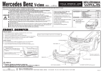
fineline6
rm
ere
pa
i
ic
se
rv
Brother Laser Printer
SERVICE MANUAL
MODEL:
HL-5240/5250DN/5270DN/5280DW
Read this manual thoroughly before maintenance work.
Keep this manual in a convenient place for quick and easy reference at all times.
September 2005
SM-PRN057
(11)
Confidential
fineline6
l.c
om
ua
an
irm
pa
re
ic
erv
se
© Copyright Brother Industries, Ltd. 2005
Compilation and Publication:
This manual has been complied and published, under the supervision of Brother Industries
Ltd., covering the latest product descriptions and specifications. The contents of this manual
and the specifications of this product are subject to change without notice. Brother reserves
the right to make changes without notice in the specifications and materials contained herein
and shall not be responsible for any damages (including consequential) caused by reliance on
the materials presented, including but not limited to typographical and other errors relating to
the publication. This product is designed for use in a professional environment.
Trademarks:
The Brother logo is a registered trademark of Brother Industries, Ltd.
Apple, the Apple Logo, Macintosh and TrueType are registered trademarks of Apple
Computer, Inc in the United States and other countries.
Epson is a registered trademark and FX-80 and FX-850 are trademarks of Seiko Epson
Corporation.
Hewlett Packard is a registered trademark and HP LaserJet 6P, 6L, 5P, 5L, 4, 4L 4P, III, IIIP,
II, and IIP are trademarks of Hewlett-Packard Company.
IBM, IBM PC, and Proprinter are registered trademarks of International Business Machines
Corporation.
Microsoft, MS-DOS, Windows and Windows NT are registered trademarks of Microsoft
Corporation in the U.S. and other countries.
ENERGY STAR is a U.S. registered mark.
Citrix and MetaFrame are registered trademarks of Citrix Systems, Inc. in the United State.
SuSE is a registered trademark of SuSE Linux AG.
RED HAT is a registered trademark of Red Hat. Inc.
Mandrake is a registered trademark of Mandrake Soft SA.
PostScript and PostScript 3 are trademarks of Adobe Systems Incorporated.
Intel, Intel Xeon and Pentium are trademarks or registered trademarks of Intel Corporation.
AMD, AMD Athlon, AMD Opeteron and combinations thereof, are trademarks of Advanced
Micro Devices, Inc.
Java and all Java-based trademarks and logos are trademarks or registered trademarks of
Sun Microsystems, Inc. in the United States and other countries.
All other terms and brand and product names mentioned in this Service Manual are registered
trademarks of their respective companies.
Confidential
fineline6
l.c
om
PREFACE
irm
an
ua
This service manual contains basic information required for after-sales service of the laser
printer (hereinafter referred to as "this machine" or "the printer"). This information is vital to
the service technician to maintain the high printing quality and performance of the printer.
pa
This service manual covers the HL-5240/5250DN/5270DN/5280DW printers.
ic
e-
re
This manual consists of the following chapters:
GENERAL
Features, specifications, etc.
CHAPTER 2:
THEORY OF OPERATION
Basic operation of the mechanical system, the electrical system and the
electrical circuits.
CHAPTER 3:
PERIODIC MAINTENANCE
Periodical replacement parts, consumable parts, etc.
CHAPTER 4:
TROUBLESHOOTING
Reference values and adjustments, troubleshooting image defects,
troubleshooting malfunctions, etc.
CHAPTER 5:
DISASSEMBLY AND RE-ASSEMBLY
Procedures for disassembling and re-assembling the mechanical
system.
CHAPTER 6:
ADJUSTMENTS AND UPDATING OF SETTING, REQUIRED AFTER
PARTS REPLACEMENT
CHAPTER 7:
SERVICE SUPPORT SOFTWARE
Test print mode and Service menu mode, etc.
APPENDIX:
Diagrams etc…
se
rv
CHAPTER 1:
Information in this manual is subject to change due to improvement or redesign of the
product. All relevant information in such cases will be supplied in service information
bulletins (Technical Information).
A thorough understanding of this printer, based on information in this service manual and
service information bulletins, is required for maintaining its print quality performance and
for improving the practical ability to find the cause of problems.
i
Confidential
fineline6
TABLE OF CONTENTS
REGULATION ............................................................................................ viii
SAFETY INFORMATION .............................................................................. x
CHAPTER 1 GENERAL........................................................................... 1-1
1.
FEATURES............................................................................................................. 1-1
2.
PARTS NAMES AND FUNCTIONS ........................................................................ 1-3
Overview........................................................................................................................... 1-3
2.2
Control Panel.................................................................................................................... 1-5
SPECIFICATIONS .................................................................................................. 1-7
Printing ............................................................................................................................. 1-7
3.2
Functions .......................................................................................................................... 1-8
3.3
Electronics and Mechanics............................................................................................. 1-11
3.4
Service Information......................................................................................................... 1-12
3.5
Network Connectivity.............................................................. .. ................................... 1-12
3.6
Paper ................................................................................ ... ......................................... 1-14
om
3.1
l.c
3.
2.1
ua
3.6.1 Paper handling ......................................................... . .....................................................1-14
Printable Area................................................. . ............................................................. 1-17
irm
3.7
an
3.6.2 Media specifications.......................................... ... ...........................................................1-14
pa
3.7.1 PCL5e/EPSON/IBM emulation ............... ..........................................................................1-17
Print Speeds with Various Settings .............................................................................. 1-21
3.9
Toner Cartridge Weight Information............................................................................... 1-22
rv
ic
e-
3.8
SERIAL NO. DESCRIPTIONS .............................................................................. 1-23
se
4.
re
3.7.2 PCL6 emulation............................. . ... .............................................................................1-20
CHAPTER 2 THEORY OF OPERATION................................................. 2-1
1.
OVERALL ............................................................................................................... 2-1
1.1
2.
General Block Diagram .................................................................................................... 2-1
ELECTRONICS ...................................................................................................... 2-2
2.1
General Block Diagram .................................................................................................... 2-2
2.2
Main PCB Block Diagram ................................................................................................. 2-3
2.3
Main PCB ......................................................................................................................... 2-4
2.3.1 CPU.....................................................................................................................................2-4
2.3.2 USB interface (2.0 High Speed) ..........................................................................................2-4
2.3.3 IEEE 1284 interface ............................................................................................................2-4
2.3.4 Network interface ................................................................................................................2-4
2.3.5 ROM ....................................................................................................................................2-4
2.3.6 SDRAM ...............................................................................................................................2-4
2.3.7 Optional RAM ......................................................................................................................2-4
2.3.8 EEPROM.............................................................................................................................2-4
ii
Confidential
fineline6
HL-5240/5250DN/5270DN/5280DW SERVICE MANUAL
2.3.9 Reset circuit ........................................................................................................................2-5
2.3.10 Panel I/O .............................................................................................................................2-5
2.3.11 Video I/O .............................................................................................................................2-5
2.3.12 Power supply.......................................................................................................................2-5
2.3.13 Wireless LAN ......................................................................................................................2-5
2.4
Power Supply.................................................................................................................... 2-6
2.4.1 Low-voltage power supply...................................................................................................2-6
MECHANICS ................. .. ..................................................................................... 2-7
Overview of Printing Mechanism ...................................................................................... 2-7
3.2
Overview of Gear.............................................................................................................. 2-8
3.3
Paper Transfer ................................................................................................................. 2-9
an
ua
l
3.1
rm
3.
.c
om
2.4.2 High-voltage power supply ..................................................................................................2-6
ere
pa
i
3.3.1 Paper supply .......................................................................................................................2-9
3.3.2 Paper registration..............................................................................................................2-11
se
rv
ic
3 3.3 Drum unit...........................................................................................................................2-11
3.3.4 Developing ........................................................................................................................2-12
3.3.5 Fixing stage .......................................................................................................................2-13
3.3.6 Paper eject ........................................................................................................................2-14
3.3.7 Duplex printing (HL-5250DN/5270DN/5280DW)...............................................................2-15
3.3.8 Paper feeding from the MP tray ........................................................................................2-16
3.3.9 LT tray ...............................................................................................................................2-16
3.4
Toner Cartridge .............................................................................................................. 2-17
3.4.1 Toner life end mode ..........................................................................................................2-17
3.4.2 New toner detection mechanism .......................................................................................2-19
3.4.3 Counter reset during indication of “Toner Life End” ..........................................................2-20
3.5
Print Process .................................................................................................................. 2-21
3.5.1 Charging............................................................................................................................2-21
3.5.2 Exposure stage .................................................................................................................2-21
3.5.3 Transfer .............................................................................................................................2-22
3.6
Sensors .......................................................................................................................... 2-23
3.7
Heat Control of Fuser Unit.............................................................................................. 2-24
CHAPTER 3 PERIODIC MAINTENANCE ............................................... 3-1
1.
2.
CONSUMABLE PARTS .......................................................................................... 3-1
1.1
Toner Cartridge ................................................................................................................ 3-1
1.2
Drum Unit ......................................................................................................................... 3-7
PERIODICAL REPLACEMENT PARTS ................................................................ 3-12
2.1
Periodical Replacement Parts ........................................................................................ 3-12
2.2
Procedures to Replace Periodical Replacement Parts .................................................. 3-13
2.2.1 Fuser unit and laser unit....................................................................................................3-13
2.2.2 Paper feeding kit for tray 1, 2, 3 ........................................................................................3-35
2.2.3 Paper feeding kit for MP tray.............................................................................................3-43
iii
Confidential
fineline6
3.
PERIODICAL CLEANING ..................................................................................... 3-49
3.1
3.2
Cleaning the Inside of the Printer ................................................................................... 3-49
Cleaning the Corona Wire .............................................................................................. 3-52
CHAPTER 4 TROUBLESHOOTING ....................................................... 4-1
1.
2.
INTRODUCTION .................................................................................................... 4-1
1.1
Initial Check ...................................................................................................................... 4-1
1.2
Warnings for Maintenance Work...................................................................................... 4-2
1.3
Identify the Problem.......................................................................................................... 4-3
ERROR MESSAGE ................................................................................................ 4-4
2.1
Operator Calls .................................................................................................................. 4-4
2.1.1 Operator calls for HL-5240/5250DN....................................................................................4-4
2.1.2 Operator calls for HL-5270DN/5280DW..............................................................................4-6
2.2
Service Calls..................................................................................................................... 4-8
2.2.1 Service calls for HL-5240/5250DN ......................................................................................4-8
2.2.2 Service calls for HL-5270DN/5280DW ..............................................................................4-10
3.
2.3
Error Message in the Status Monitor .............................................................................. 4-12
2.4
Error Message Printouts................................................................................................. 4-14
PAPER PROBLEMS ............................................................................................. 4-15
3.1
Paper Loading Problems ................................................................................................ 4-15
3.2
Paper Jams .................................................................................................................... 4-16
3.2.1 Paper jams and how to clear them for HL-5240/5250DN..................................................4-16
3.2.2 Paper jams and how to clear them for HL-5270DN/5280DW ..........................................4-18
Paper Feeding Problems........ ...... ................................................................................ 4-27
l.c
3.3
om
3.2.3 Causes & countermeasures....... ......................................................................................4-26
SOFTWARE SETTING PROBLEMS .................................................................... 4-29
5.
MALFUNCTIONS............ . .................................................................................. 4-32
6.
IMAGE DEFECTS..... . ......................................................................................... 4-38
pa
irm
an
ua
4.
Image Defect Examples ................................................................................................. 4-38
6.2
Diameter of Rollers......................................................................................................... 4-38
6.3
Troubleshooting Image Defect ....................................................................................... 4-39
6.4
Location of Grounding Contacts ..................................................................................... 4-57
se
rv
ic
e
-re
6.1
6.4.1 Drum unit...........................................................................................................................4-57
6.4.2 Printer body & Paper tray ..................................................................................................4-57
7.
INCORRECT PRINTOUT ..................................................................................... 4-58
8.
NETWORK PROBLEM ......................................................................................... 4-60
8.1
Installation Problem ........................................................................................................ 4-60
8.2
Printing Problem ............................................................................................................. 4-63
8.3
Protocol-Specific Troubleshooting.................................................................................. 4-65
8.4
Wireless Network Troubleshooting ................................................................................ 4-66
iv
Confidential
fineline6
HL-5240/5250DN/5270DN/5280DW SERVICE MANUAL
CHAPTER 5 DISASSEMBLY AND RE-ASSEMBLY .............................. 5-1
1.
SAFETY PRECAUTIONS ....................................................................................... 5-1
2.
PACKING................................................................................................................ 5-2
3.
SCREW TORQUE LIST.......................................................................................... 5-3
4.
HARNESS ROUTING ............................................................................................. 5-4
5.
LUBRICATION...................................................................................................... 5-13
6.
DISASSEMBLY FLOW ......................................................................................... 5-14
7.
DISASSEMBLY PROCEDURE ............................................................................. 5-15
AC Cord................................... ...................................................................................... 5-15
7.2
Drum/Toner ASSY.......................................................................................................... 5-15
7.3
DX Feed ASSY............ . ................................................................................................ 5-16
7.4
Paper Tray............ ... ..................................................................................................... 5-16
7.5
Back Cover ....... ............................................................................................................. 5-20
7.6
DX Blank Cover (For HL-5240) ...................................................................................... 5-20
7.7
Outer Chute ASSY ......................................................................................................... 5-21
7.8
Fuser Unit ....................................................................................................................... 5-23
7.9
Tray MP ASSY................................................................................................................ 5-25
se
rv
ic
e-
re
pa
irm
an
ua
l
.c
om
7.1
7.10 MP Tray Cover ASSY/Process Cover ASSY.................................................................. 5-26
7.11 Access Cover/ Side Cover L........................................................................................... 5-28
7.12 Main PCB ....................................................................................................................... 5-29
7.13 Gear Plate Calking ASSY AL/Develop Joint/Main Motor ASSY AL................................ 5-30
7.14 Main Shield Plate ASSY ................................................................................................. 5-32
7.15 Relay Rear PCB ASSY/Connector ................................................................................. 5-34
7.16 Relay Front PCB ASSY .................................................................................................. 5-36
7.17 MP Solenoid ASSY......................................................................................................... 5-37
7.18 Drive Release Link ......................................................................................................... 5-38
7.19 T1 Solenoid ASSY.......................................................................................................... 5-39
7.20 Toner Sensor PCB ......................................................................................................... 5-39
7.21 Register Solenoid ASSY................................................................................................. 5-40
7.22 Ejector Solenoid ASSY (For HL-5250DN/5270DN/5280DW)......................................... 5-40
7.23 Interlock SW ASSY ........................................................................................................ 5-41
7.24 New Toner Actuator........................................................................................................ 5-41
7.25 Gear 17/20...................................................................................................................... 5-42
7.26 Side Cover R .................................................................................................................. 5-44
7.27-1 Top Cover Printed ASSY (For HL-5240/5250DN) ........................................................ 5-45
7.27-2 Panel PCB ASSY.......................................................................................................... 5-45
7.27-3 SW Key A/B .................................................................................................................. 5-46
7.27-4 Inner Chute/Pinch Roller Holder ................................................................................... 5-47
v
Confidential
fineline6
HL-5240/5250DN/5270DN/5280DW SERVICE MANUAL
7.28-1 Top Cover 2 Printed ASSY/Panel Plate Printed ASSY (For HL-5270DN/5280DW) ... 5-48
7.28-2 Inner Chute/Pinch Roller Holder .................................................................................. 5-49
7.28-3 Panel PCB ASSY ......................................................................................................... 5-50
7.28-4 SW Key A/B/C/ Set Key Printed ASSY ........................................................................ 5-51
7.28-5 LCD Holder ASSY........................................................................................................ 5-53
7.29 Filter ............................................................................................................................... 5-55
7.30 Laser Unit....................................................................................................................... 5-56
7.31 PS PCB Unit................................................................................................................... 5-57
7.32 High-Voltage PS PCB ASSY ......................................................................................... 5-60
7.33 Toner LED PCB Unit ASSY ........................................................................................... 5-62
7.34 Fan Motor 60 Unit .......................................................................................................... 5-63
7.35 Fan Motor 60 Unit LV..................................................................................................... 5-63
7.36 Frame L.......................................................................................................................... 5-64
7.37 Frame R ......................................................................................................................... 5-64
7.38 MP Unit .......................................................................................................................... 5-65
7.39 Regist Actuator Rear/Regist Actuator Spring ................................................................ 5-70
7.40 Regist Actuator Front/Regist Actuator Spring................................................................ 5-72
7.41 Roller Holder ASSY ....................................................................................................... 5-73
7.42 PE Actuator, Edge Actuator, Edge Actuator Spring ...................................................... 5-74
7.43 PE PG Sensor ASSY ..................................................................................................... 5-76
7.44 Wireless PCB (PCB T60H929.00 ASSY 02) (For HL-5280DW) ................................... 5-77
om
DISASSEMBLY PROCEDURE (LT-5300)..................................................... .. .....5-78
Paper Tray ..................................................................................................................... 5-78
8.2
LT Front Cover ASSY ........................................................................... .. ..................... 5-81
8.3
LT Rear Cover................................................................................. ... .......................... 5-82
8.4
LT Side Cover L .......................................................................... .................................. 5-82
8.5
LT Side Cover R................................................................. . . ...................................... 5-83
8.6
LT PCB ASSY ............................................................... ................................................ 5-84
8.7
Connector: 55533-1219 ....................................... . .. .................................................... 5-85
8.8
Connector: 54702-1219 .................................. . ........................................................... 5-85
8.9
Gear 24LT .................................................... ................................................................ 5-86
rv
ic
e
-re
pa
irm
an
ua
l.c
8.1
se
8.
8.10 Collar 6........................................................................................................................... 5-87
8.11 LT Solenoid ASSY ......................................................................................................... 5-91
8.12 Roller Holder ASSY ....................................................................................................... 5-92
8.13 Edge Actuator Spring..................................................................................................... 5-93
8.14 PE Actuator, Edge Actuator ........................................................................................... 5-94
8.15 LT Sensor PCB ASSY ................................................................................................... 5-95
vii
Confidential
CHAPTER 6 ADJUSTMENTS AND UPDATING OF SETTINGS,
REQUIRED AFTER PARTS REPLACEMENT.................. 6-1
1.
IF YOU REPLACE THE MAIN PCB ..........................................................................6-1
2.
IF YOU REPLACE THE PERIODICAL MAINTENANCE PARTS ............................6-10
CHAPTER 7 SERVICE SUPPORT SOFTWARE.................................... 7-1
2.
3.
CONTROL PANEL ....................................................................................................7-1
1.1
Users Mode...................................................................................................................... 7-1
1.2
User Maintenance Mode.................................................................................................. 7-3
1.3
Service Mode ................................................................................................................... 7-5
HIDDEN FUNCTION MENUS .................................................................................7-15
2.1
Professional Menu ......................................................................................................... 7-16
2.2
Reset Parts Life Menu ................................................................................................... 7-23
2.3
Service Menu ................................................................................................................. 7-24
NVRAM DEFAULT VALUE......................................................................................7-29
l.c
APPENDIX
om
1.
MAIN PCB CIRCUIT DIAGRAM ............................................................................... A-1
2.
LOW-VOLTAGE POWER SUPPLY PCB CIRCUIT DIAGRAM (100V, 200V).......... A-8
3.
HIGH-VOLTAGE POWER SUPPLY PCB CIRCUIT DIAGRAM ............................. A-10
irm
POINT TO POINT CONNECTION DIAGRAM ........................................................ A-11
pa
4.
an
ua
1.
GEAR LAYOUT DRAWING.................................................................................... A-12
6.
READMARKS ......................................................................................................... A-14
7.
LOCATION OF THE FERRITE CORE ................................................................... A-15
se
rv
ic
ere
5.
fineline6
viii
Confidential