1
EPM420
MultiFunction
Power
Monitor
V.2.0
W E
M A K E
P O W E R
S M A R T
3
Table of Content
Table of Content
Introduction
Product overview
What is EPM420
Basic Introduction
Measurement Principles
System description
Feature
EPM SPECIFICATION
Product structure
Modular construction
Analog module
Power module
Controller module
Front panel
Rear connection
Button function
Programming your meter
EPM420set-up
PT Table
CT Table
Installation
Initialization
Topology
Wiring Diagram
Maintenance/ troubleshooting
Preventive maintenance
Troubleshooting
Appendix
Drawing
Communication Protocol
DM323210,RD 6/2000
EPM420 Users Manual
4
Table of Content
COPY RIGHT
This Service Manual is copyrighted and all rights are reserved. The
distribution and sale of this manual are intended for the use of the original
purchaser or his agents. This document may not, in whole or part, be copied,
photocopied, reproduced, translated or reduced to any electronic medium or
machine-readable form without prior consent of Dae Instrument, Inc., except
for use by the original purchaser.
INSTALLLATION AND
MAINTENANCE
Dae's products are designed for ease of installation and maintenance. As
with any product of this nature, however, such installation and maintenance
can present electrical hazards and should only be performed by properly
trained and qualified personnel.
WARRANTY AND
ASSISTANCE
All Dae's Multifunction instruments are warranted for on year against
defects in materials and workmanship under normal use and service.
Obligation part or parts which Dae's examination should be defective. There
are no other warranties, obligations, liabilities for consequential damages, or
other defective materials or work workmanship. The warranties of
merchantability and fitness for a particular purpose are expressly excluded
NOTICE
Read these instruction carefully and look at the equipment to become familiar
with the device before trying to install, operate,or maintain it.The following
special message may appear throughout this bulletin to warn of potential
hazards or to call attention to information that clarifies or simplifies a
procedure.
DANGER
Used where there is hazard of serious injury of
death.Faiture to follow a “DANGER” instruction
will result in deeath or serious injury.
-WARNING
Used where there is hazard of serious injury or
death.Failure to follow a “WARNING”
instruction can result in death or injury. Table of Content
DM323210,RD 6/2000
EPM420 Users Manual
5
CAUTION
Used where there is hazards of equipment
damage.Failure to follow a “CAUTION”
instruction can result in damage to
equipment.
PLEASE NOTICE
DM323210,RD 6/2000
Electric equipment should be serviced only by qualified maintenance
personnel, and this document should not be viewed as sufficient for those
who are not otherwise qualified to operate, service, or maintain the
equipment discussed. Although reasonable care has been taken to provide
accurate and authoritative information in this document, no responsibility
is assumed by DAE INSTRUMENT for any consequence arising out of the
use of this material.
EPM420 Users Manual
6
Chapter 1--Introduction
1. Introduction
Product overview Current and voltage, as well as real and reactive power are essential
What is EPM420
Basic
Introduction
Measuring Function
quantities, which must be measured accurately in order to optimize the
control and delivery of electric power. The use of state of the Art”
microprocessor technology assures digital accuracy and repeatability across
a wide range of input signal levels. EPM series are rugged electronic
instruments designed for utility and industrial applications requiring
standard. The meters are modular in design, with push-button rescaling to
display primary values when using any standard current and voltage
transformer. Rescaling can be done in the field, in a matter of minutes,
without removing the instrument from the panel or the need for any
calibration equipment. EPM series also provides the user with the capability
to connect directly with Modbus-RTU protocols. This capability allows users
to seamlessly integrate the meters into an existing or planned SCADA or
PLC .
EPM420 multi-function digital power monitoring meter is one kind of
full-function intelligent power monitoring instruments. These devices not
only provide all requirements in power measurement but also solving the
problem of the complicated traditional wiring and commission. EPM420
greatly simplify the traditional complicated electric power automation
wiring and commission and replace the related component such as
Transducers and RTUs.EPM420 is basic crucial equipment essential for the
modernization of power automation system.
EPM420 can measure 3-phase voltage and 3 phase current, with kW, Kr, pf,
kWh, kvarh simultaneously and updated the measurement reading every
0.4-sec. It can be operated no matter in 3 phase 3wire or 3 phase 4 wire .The
users can set the parameter such as PT ratio, CT ratio, wiring form, to fulfill
the different requirement through front panel to use different wire forms in
different wire mode.
Measuring Accuracy: This device is calibrated fully by digital system, and there is no variable
resistance provided to be adjusted. The calibration factor is storage in
EEPROM and needless to readjust in 3 years .To order to increase the
accuracy of measurement, adjusting parameter in 3 phase 4wire and 3 phase
3wire are separately measured and storage in their own memory register.
The current input minimum great than 0.35A ,threshold value otherwise will
cause the PF measurement incorrect.
DM323210,RD 6/2000
EPM420 Users Manual
1-2
7
Chapter 1--Introduction
Operator Interface: In order to provide clear display of measurement reading in long distance ,
EPM420 adopt LED in large size. So that the users of EPM420 can observe
the measurement reading directly.
To be a high-reliable power instrument, there are two key factors to be
concerned: being able to operate in high-temperature and owning a long life
span. These two factors are what LED advantage. Compared with LED, LCD
would like to deteriorate when constantly operating in high-temperature .As
a result,Led is adopted.
Simple Installation EPM420 is the installation of DIN144 x 144.The depth of this device is only
7cm,so that it’s just needed very shallow space to use. There are some brands
limited in this, so the display mode and module must be take apart. This will
result extra cost in installation. In proportion to EPM420,the installation of
EPM420 is much easier.
Digital
communication
EPM420 provides Isolated RS-485 communication, and communicational
rate up to 19200bps,being able to intensify communication response time
between the meter and the computer.
At the same time,EPM420 provide quite great ability of telecommunication
response , being able to order the computer send the measuring value back
in 125 msec .It is very important to the users who want to have rapid
datacommunication response when using many meters.
This device adopts Modbus-Rtu communicational protocol, conscientiously
and carefully designed, reliable, linked with most monitoring software easily
and needless to design extra interface, reducing cost. This device also can be
connecting to PLC, being slave equipment of PLC, via PLC integrating to be
a large-scale of automatic system.
Measurement
Principles
All the quantities measured by the Meters instrument utilize digital signal
processing (DSP) technique. This technique allows the instrument to
measure a large number of quantities with a small amount of hardware. It
also allows field upgrades, since the signal processing algorithms are in an
EPROM, and can be simply updated to provide new features. The following
section will give a brief overview of the measurement principles.
Voltage/Current
signal processing begins with the low level AC signal supplied from the
power board which is about 1 Vac RMS for a full scale input signal. Pure sine
wave inputs or complex, distorted, periodic waveforms are handled equally
well a major advantage when computing Watts and Vars. As well as true
RMS currents and voltages. This design frees the user from concern about
errors, which will otherwise occur during the measurement of distorted
waveforms. Phases A, B and C are samples in succession, providing the
MCU with instantaneous measurements of all voltage and current inputs.
Samples are accumulated for 1 seconds, at which time the MCU calculates
the Volts and Amps for each phase. Any Zero Offset or drift is compensated
every calculation cycle. Once the Volts and Amps have been calculated, the
MCU scales the values by the external PT and CT ratios, which have been
Chapter 1--Introduction
selected by the user, and displays the values.
Watts/VARs
Instantaneous Watt samples are accumulated for 0.4 seconds, at which time
the MCU calculates the Watts and Vas for each phase. The VARS quantity for
DM323210,RD 6/2000
EPM420 Users Manual
8
each phase is derived from a power triangle calculation where the WATTS
and Vas are known. This technique provides a true” measure of VARs even
with distorted waveforms. Zero offset is slow adjusted for each signal
channel every 0.4 seconds by the MCU. These per phase quantities are then
summed to form the total three phase WATTS and VARS. Once the WATTS
and VARS have been calculated, the MCU scales the values by the external
PT and CT ratios, which have been selected by the user, and displays the
primary values.
Energy
The WATT and VAR values are calculated every 0.4 second. These values are
then multiplied by a factor in order to generate Watt-hours and VAR-hours.
The sign of the Watt-hours and VAR-hour values are then checked, and the
values are then added to the appropriate registers (Positive/Negative
WATThours, VARhours). In order to retain the energy values during a power
failure, the registers must be stored in the EEPROM in the base of the
instrument, The EEPROM has a limited number of write cycles, so the
energy are only written every 90 seconds. At this rate, the EEPROM will last
in excess of 15 years at rated conditions. The registers are in primary
kilowatt-hours and kilo VAR-hours, and the CT and PT ratio are used to
calculate the primary units.
The Energy registers count to a maximum of 10000000 kWh before rolling
over to zero. It is the responsibility of the user to ensure that these values are
read often enough to detect every rollover.
Frequency
The Frequency measurement is generated by timing zero-crossings of the
Phase A Voltage (Phase A-B) over a period of 0.6 seconds. Knowing the
number of zero-crossings and time between them, the frequency can be
calculated. A rolling average of two measurements helps to reduce the
fluctuations in the measurement. The input voltage must be greater than
10Vac for the frequency function to determine a value.
Power factor
The Power Factor measurements require a secondary side of CT current of
minimum 0.25Aac and a secondary side of PT voltage approximately 50Vac
to determine an accurate answer. If the input signals are below these values
the power factor ready will be displayed at 1.00 .
DM323210,RD 6/2000
EPM420 Users Manual
9
Chapter 2--System Description
2.System Description
Feature
All measured quantities available over the digital communications
channel to SCADA or PLC systems.
Push-button rescaling in the field accommodates all ANSI CT and PT
ratios. displays the primary values.
Non-volatile memory backup of CT/PT settings energy readings,
communication settings. No batteries are needed.
Separate second microprocessor to off-load the main processor
Standard Universal power supply works on AC or DC service, (110v
or 230V )
True RMS measurements are standard.
DIN size 144*144 enclosures
4 digits by 3 lines high efficiency LEDs for easy reading
Watchdog timer maximizes system reliability
EPM
SPECIFICATION
Voltage inputs
Current inputs
Frequency
Low Burden
Power measurement
Accuracy
Microprocessor
Display
DM323210,RD 6/2000
Rating
Max
Overload
Sensing method
Rating:
Overload
Sensing method
Range
PT Burden
CT Burden
Line voltage
Phase voltage
Current
3 phase total
Energy total
Current and voltage
Other power functions
Frequency
Microprocessor
Data display
Power parameter
Update time
Auto scaling
EPM420 Users Manual
120vac, 400vac(L/N)
600 VAC Max. between L/L
400VAC Max between L/N
2 x rating continuous
True-RMS
5 Amps with 20% over range
15 Amps continuous
250 Amps for 1 sec. non-recurring
True-RMS
40-100 Hz
0.2 VA
0.2 VA
Per phase
Per Phase (3p4w only)
Per phase
f, PF, KW, KVAR
Kwh, Kvarh (import and export)
0.5%,FS; 0.2% FS (optional)
1%,FS; 0.5%(optional)
0.1Hz
16 bit low power MPU
32K-byte non-volatile RAM
4K bit EEPEROM
3 lines of 4 digits data LED display
18 LED display
0.5 sec
Available
10
Chapter 2--System Description
User configuration parameters
Setting
Parameter setting
Isolated RS485 communication
Seals
Environment
Dimension & weight
Standards apply
Isolation
Isolation
Address
Baud rate
Distance
Protocol
Front panel
Terminal
Operating
Terminal
Dimension
Weight
IEC
ANSI
UL
Input/output/ground
Insulation
Power supply
Input
Consumption
Keyboard
Saved in EEPROM , no parameters
are required to maintain data
PT/CT table select ratio,
RS 485address, Baud rate
Photo isolation 2500 Vrms
Up to 32 EPM420 per line
up to 19200 bps
4000 ft.
Modbus-RTU mod
IP41/UL94
IP20
-20 ~ 70 deg. C
IP20
144*144*90mm
1kg
IEC870,IEC801-4
ANSI 37.9/IEEE-472 SWC
UL94
2500 vac, between any input and
output; 2800vac between I/O and
ground
500M ohm, between any I/O and
case
115/230 V (20%),AC or DC
3.5 VA
Measuring range
Real-time reading
Current per phase
Voltage L-L per phase
Voltage L-N per phase
Real power 3 phase total
Reactive power 3 phase total
Apparent power 3 phase total
Power factor 3 phase total
Frequency(50/60Hz)
KWH 3 phase total
KVARH 3 phase total
Table 2-1
DM323210,RD 6/2000
EPM420 Users Manual
Range
0 to 7500A
0 to 35KV
0to 230KV
0to 9999Kw
0 to 9999Kw
0 to 9999Kw
-1 to 1
40 to 70 Hz
1000000.0Kwh
1000000.0Kwh
11
Chapter 3--Product Structure
3.Product Structure
Modular
construction
The EPM Series Meters are composed of three major modules. The analog
module and controller module, and power supply module .
The analog module is installed at backside while controller module at the
front side; the power module is attached by analog module. The analog
Module contains passive parts (transformers, connectors , etc.) and cannot be
serviced without removal from the panel. The controller consists of the
analog and digital Processing, dual Micro controller, and the LED Displays.
This module can easily be removed for maintenance without the need to
remove the meter from the panel, or to remove the meter from service.
Analog module
The analog module consists of the input and power connector, the initial
current transformer, analog circuit, communication transceiver, input
protection circuitry, instrument potential transformer EEPROM.
The meters provide for complete interchangeability among analog module
and controller modules. Compensation for normal variations in input
circuits is achieved by storing calibration constants in a non-volatile
memory (EEPROM) which resides on the PC board. These constants are
factory programmed to provide identical signal gain (attenuation) in each of
the six isolated signal input paths. The CT and PT settings for scaling the
display to the user's CTs and PTs are also stored in this EEPROM. The
Energy Registers are also stored in this EEPROM.
Detailed descriptions of each of the boards can be found in the following
sections.
Input signal
connections
The EPM420 have 10 independent signal input ;6 current and 4voltage for
each phase being measured .The signal input of voltage and current are
directly connected to the rear panel of the meter in #10-32 AWG .The meter
can be connected directly to CTs or PTs and can directly connected if the
voltage is lower than 600 volts.
The internal of CT and PT have a feature of low burden rate ,so that it almost
no loading effects on the secondary value of PT and CT .It must be paid
attention that the polarity and order sequence in PT or CT input .The wiring
error will not cause any anxiety in security but there will some problems in
reading errors.
And it must be noted that:When connecting PTs or CTs , all kind of
protecting and prevent measures must be adopted to stave off the burning
out of equipments.
The meter have power of MOV ,confirming ANSI / IEEE C57.13.13-1983.
Communication
connector
Internal CT
The meter have the isolated communicational interface of RS485 in the upper
right side of the rear panel .
The internal CT in the meter provides good function of isolation and meter
protection and simultaneously avoids that the monitored equipment
open-circuit (result in melt and electric accident). The internal I/O capability
uppers to 1500 volts.
Chapter 3--Product Structure
DM323210,RD 6/2000
EPM420 Users Manual
12
Internal potential
transformer
Power module
Switching power
Supply
Working power
supply
Controller
module
The potential transformer (PT) contain secondary transformers , which
provide electrical isolation for each of the signal-input channels. Voltage
from the PT terminal flows though a internal PT to assure that the user's
external PT circuit can never open-circuit, even under extreme fault
conditions. The use of transformer isolation on all input leads provides
excellent isolation (>1500Vac) between the inputs and any output.
The meters have a universal power supply as a standard feature. The
universal power supply is a high-efficiency, high frequency switching power
supply with integrated over-current protection. Power from the input
terminals is conducted to a full-wave bridge rectifier and converts AC power
inputs to DC.. The output of the switching supply is then post regulated by a
low-drop linear regulator to provide precise supply voltage control under all
conditions.
The total load required to operate is only 3.5VA. It is therefore possible to power
the EPM Series Meter with AC or DC station power or an auxiliary PT or battery.
The meter are designed in Aac or Vac in power input(110 or 220volts),and the
terminal is designed in the upper left side of rear panel(terminal 1 and 2). In
order to assure the operation of meter monitoring ,the power supply of the
meter should separately set ,especially in low voltage for the working power
should maintain its good electric quality and the monitored power may be
harmful electric quality .In applying high voltage, the meter can directly
connected to 110 or 220 Aac volts for the working power supply.
Analog processing
The function of analog processing is to sample and digitize the
micro-controller (MCU) for further processing. Calibration constants stored in
the analog module
EEPROM to provide drift-free calibration, and
complete interchangeability of analog processing.
Master
micro-controller
The master micro-controller consists of an 16-bit micro-controller, address latc
memory and a watchdog timer. All the data acquisition, signal processing and
manipulation are controlled by this micro-controller. Communications to most
other boards is accomplished via a serial data link consisting of three lines
common to all the other devices.
Slave
micro-controller
The micro-controller consists of an 8-bit micro-controller, address latch, EPROM
memory, dual port ram. This processor performs all the front panel operation and
communication functions. Utilized this slave processor can share the load of main
processor to enhance the response speed. The dual port RAM for pass messages”
between master and slave micro controller in order to service operator's LED
display and data communication function.
DM323210,RD 6/2000
EPM420 Users Manual
13
Chapter 3--Product Structure
EEPROM
LED display
DM323210,RD 6/2000
The meter configuration and data(max. demand,max. current, happen time
can be preserved in EEPROM even loss of power.
The LED Display sets consist of three 4-digit displays comprised of high
efficiency red LED seven segment common cathode displays. Each 4 digit
display is driven in a multiplexed fashion by an seven segment decoder driver
chip, which accepts serial data from the slave processor, and decodes the data
into seven segment and digit select outputs necessary for the multiplexed
display. An driver provides the high current cathode drive for each pair of
digits.
EPM420 Users Manual
14
Chapter 3--Product Structure
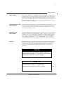
Front Panel
E+q
S
PF
F
V1
V12
I1
V2
V23
I2
V3
V31
I3
FUN
V/A
I
E+p
Q
Display
measurement
reading.
Power
Function
List:
This list displays
system
measurements. Each
of the line show
different
measurement.
Table 3-1 Power Function List
SYMBOL
V1
V2
V3
V12
V23
V31
I1
I2
I3
P
Q
S
PF
F
E P+
E Q+
DEFINITION
Phase R voltage
Phase S voltage
Phase T voltage
Line RS voltage.
Line ST voltage.
Line TR voltage.
Phase R current
Phase S current
Phase T current
Real power
Kvar
Apparent power
Power factor
Frequency
Kwh(import)
Kvarh(import)
DM323210,RD 6/2000
UNIT
Kv or V
Kv or V
Kv or V
Kv or V
Kv or V
Kv or V
Amp
Amp
Amp
Kw or Mw
Kw or Mw
Kw or Mw
ANNOTATIONS
PT ratio = 1(low voltage),the uint is "V"
PT ratio = other value(mideum or high
voltage),the unit is "Kv".
V1,V2,V3 are uesd when in 3 phase 3 wire.
Hz
0.1Kwh
0.1Kwh
Base on voltage Phase A
PT ratio >1000,the unit is Mw
EPM420 Users Manual
15
Chapter 3--Product Structure
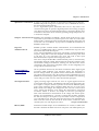
Rear Connection
AC1 AC2
G
NC
NC 485+ 485- 485S
Aux Power and
Communication
terminal.
AC aux. power
V1
V2
V3
V N I1 +
I1 -
I3 +
I2 -
I3 +
I3 -
Power
Measurement
Terminal.
Button function
Button
Display Mode
FUN
Choose the power function
V/A
Change the measurement
current or voltage
FUN
DM323210,RD 6/2000
V/A
Setting Mode
Increase the setting parameter.
of
Confirm the setting
Press the two button at the same time to enter into setting mode
EPM420 Users Manual
16
Chapter 4--Programming your meter
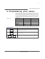
4.Programming your meter
The Meters can display several per-phase and total quantities for the circuit
being monitored. This allows the simultaneous display of all phases for a
given quantity such as AMP. The parameter ITEM LED display at the right
side of the instrument prompts the user as to what quantity is being
displayed. While this chapter will construct you step by step to learn how to
operate meters. Please refer the attachment table of PT/CT ratio index while
in set-up mode.
Parameter
Allowed Values
Defaults
Table 4-1
CT ratio
1200
1
PT1
35000*
100
PT2
220
100
Device Address
0-31
00
Baud Rate
0-5
4
Password
0-9998
0
Button function
Button
Setting Mode
FUN
Increase the setting parameter.
V/A
Confirm the setting
FUN
DM323210,RD 6/2000
V/A
Press the two button at the same time to enter into setting mode
EPM420 Users Manual
17
Chapter 4--Programming your meter
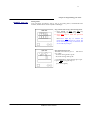
EPM420 set-up
Setting mode:
User can follow procedures, step by step to set scaling factor, communication ID
number, and Baud rate selection (9600 or 19200bps)
Step 1: Enter into set-up, select wiring mode
a. Press BOTH of FUN and V/A key
simultaneously, enter into set-up mode.
b. Press FUN key to select the password
value.
Note:“Press V/A key to confirm the
password if the password is correct, the
screen will change to step 2 otherwise ,the
screen will stay at step 1.”
Step 2: Select 3p3 or 3p4
The LED screen shows: "y i r e"
or 4. where
"3":means wiring mode is 3p3w
"4"; means wiring mode 3p4w.
and select 3
a. press FUN key to toggle change 3p3 or 3p4.
b. press V/A key to go to step 2.
(ex: 3 means.3p4w)
DM323210,RD 6/2000
EPM420 Users Manual
18
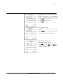
step 3: PT 1 value setting
(Pt1=primary value ; Pt2=secondary value)
The LED screen shows:" p t 1 "and "24000" (
a. press FUN key to increase no.(refer
attachment index) till correct.
b. press V/A key to go to step 3.
(ex. PT 4 : PT ratio = 110)
c. press V/A key to shift to set pt 2 and the
construction to increase pt index is same
as above.
Note: if PT primary side is 24000v
,secondary side is 120v, the PT1 should
Enter into 24000v , the PT2 should enter
Into 120V
The FUN key increments the value. Short
presses increase the value step by step.
Holding and not releasing increases the
value continuously and the incrementing
rate accelerates over time.
step 4: PT 2 ratio setting
(Pt1=primary value; Pt2=secondary value)
The LED screen shows:" p t 2 "and "120" (
a. press FUN key to increase no.(refer
attachment index) till correct.
b. press V/A key to go to step 3.
(ex. PT 4 : PT ratio = 110)
c. press V/A key to shift to set pt 2 and the
construction to increase pt index is same
as above.
EPM-420
FUN
Note: if PT primary side is 24000v
,secondary side is 120v, the PT1 should
Enter into 24000v , the PT2 should enter
Into 120V
A/V
The FUN key increments the value. Short
presses increase the value step by step.
Holding and not releasing increases the
value continuously and the incrementing
rate accelerates over time.
DM323210,RD 6/2000
EPM420 Users Manual
19
Step 6: Address ID no. setting (RS485 address
setting)
The LED screen shows : "4" (ex. ADDRESS
ID no.4, the ADDRESS ID no. could be 0-31)
a. press FUN key to increase id no. till
correct;
b. press V/A key to go to step 5
(RS485 address = 4)
step 7: Baud rate setting
The LED screen shows : "4" (ex. Baud rate ID
no.4)
a. press FUN key to increase baud rate ID
no. till correct,
(ex .bps = 4 : baud rate = 19200 bps)
step 8: Return to step1 or exit
The LED screen shows : “End”.
a. press V/A key to return to to step 1-b or
b. press BOTH of FUN and V/A key
simultaneously to exit set-up mode, and
return into display mode
DM323210,RD 6/2000
EPM420 Users Manual
20
Chapter 4--Programming your meter
Table 4-4
Baud Rate Setting Table
No:
0
1
2
3
4
Value
1200
2400
4800
9600
19200
DM323210,RD 6/2000
EPM420 Users Manual
21
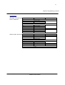
Chapter 4--Programming your meter
Operation
3p4W
Voltage ,current and
total harmonic
SYMBOL
DEFINITION
Press the V/A button
Phase R voltage
Phase S voltage
Phase T voltage
Press the V/A button
Line RS voltage.
Line ST voltage.
Line TR voltage.
Press the V/A button
Phase R current
Phase S current
Phase T current
LED DISPLAY
SYMBOL
DEFINITION
Press the FUN button
Real power
Kvar
Apparent power
Press the FUN button
Power factor
Frequency
Press the FUN button
Kwh
Press the FUN button
Kvarh
LED DISPLAY
V1
V2
V3
V12
V23
V31
I1
I2
I3
Other Power Function
P
Q
S
PF
F
E P+
E Q+
DM323210,RD 6/2000
EPM420 Users Manual
22
Chapter 4--Programming your meter
3p3W
Voltage ,current and
total harmonic
SYMBOL
V12
V23
V31
DEFINITION
Press the V/A button
Line RS voltage.
Line ST voltage.
Line TR voltage.
I1
I2
I3
Phase R current
Phase S current
Phase T current
LED DISPLAY
Other Power Function
SYMBOL
P
Q
S
PF
F
E P+
E Q+
DM323210,RD 6/2000
DEFINITION
Active power
Reactive power
Apparent power
Press the FUN button
Power factor
Frequency
Press the FUN button
Kwh(import)
Press the FUN button
Kvarh(import)
EPM420 Users Manual
LED DISPLAY
23
Chapter 5--Installation
5. Installation
Initial
Initial inspection
Instruments are carefully checked and turned in” at the factory before
shipment. Damages can occur, however, so please check the instrument for
shipping damage as it is unpacked. Notify Dae instrument immediately if
any damage has occurred, and save any damaged shipping containers.
Power requirements
EPM series Meter are normally equipped with universal (AC/DC) power
supplier. After power are connected to 110 or 220 volts ,the monitor will light
up for operation.
Over current protection
A UL listed 0.5 Ampere non-time delay (M) fuse is to be series connected in
the ungrounded (hot) side of mains input as part of installation of this
product.
Mains disconnect
The Disconnect shall be UL Recognized and acceptable for the application.
Instrument mounting Instrument mount in DIN 144 x 144 ,see figure 7-1,7-2
Surge protection
It is recommended that a metal oxide varistor (MOV) be placed across the
power supply input to protect the meter in the event of high voltage surges
or lightning strikes. EPM Meters are shipped with a transient suppression
network already attached as a standard design. An MOV provides an added
measure of protection against heavy switching transients occasionally
experienced in the field. The MOV is designed to clamp applied power
voltages above 270 V ac RMS. A single MOV protects the meter Line to Line,
and two high voltage capacitors are provided to protect each Line to
Ground. To avoid damaging the MOV protector, maintain continuously
applied power voltages within the ratings of the instrument.
Setting instrument
address
The Meters require an address to be set within the instrument before any
communications can begin. Address could be set by front panel keyboard a
display. Refer to the appropriate protocol option manual for address setup
instructions.
setting 3p3w or 3p4w The meters combined 3p3w or 3p4w configuration in the same unit, user
must set the right configuration correspondence with it's wiring.
mode
Wiring the PT and CT CT connections:
The polarity of wiring and sequence of correspondence is very
input
important .The mis-wiring with PT will result in that the reading of power
and power factor is not correct.
DM323210,RD 6/2000
EPM420 Users Manual
24
Chapter 5--Installation
Field adjustments
-WARNING
PROPERLY TRAINED OR QUALIFIED
PERSONNEL SHOULD ONLY PERFORM
WARNING-INSTALLATION &
MAINTENANCE.
Calibration
Field Service
Consideration
Routine recalibration is not recommended, or required. However some drift
or aging may cause slight errors after years of use.
If the mater requires servicing or field upgrading,you may need to
disconnect and remove the meter from its mounting .The initial installation
should be done in a way that makes this as convenient as possible:
‧ All phase voltage sense leads should be protected by breakers or fuses at
their source so that the meter can be safely disconnected.
‧ A CT shorting block should be provided so that the meter current inputs
can be safely disconnected without open circuiting the CTs. The shorting
block should be wired so that protective replaying is not affected.
‧ All wiring should be routed to allow easy removal of all connections to
the meter terminal strips and the meter itself.
Feature Pack
Requirements
A minimum of 63.5 mm(2.5”) above and below the meter should be left free
from cables,wiring,and other devices.
Terminal Strips
All connections to meter are made to terminal strips at the back of the
unit.The terminal strips for phase voltage and current are barrier-type ,for
which ring or spade terminals, or bare wire ,may be used.
The terminal strips for the communications port, and the supply power
inputs are all captured-wire type; they accept stripped wire ends.
Connecting the Base The 〒 terminal of the meter provides the safety ground connection .This
Unit Safely Ground terminal must be connected to earth ground. A good ,low impedance, safely
ground connected is essential for the meter surge and transient protection
circuitry to function effectively. It should be made to the switchgear each
ground using a dedicated AWG 14(2.1mm2) or larger wire .
Connecting the Power The meter requires a constant power supply to maintain monitoring,
analysis, control, and communications operations. Powering the meter from
Supply
the voltage source it is monitoring is not suitable for applications where
these operations must be maintained in envent of a power outage.
If an AC power supply is being used, connect the line supply wire to the
AC+ terminal and the neutral supply wire to the AC- terminal. If a DC
power supply is being used, connect the positive supply wire to the L+
terminal and the negative supply wire to the N- terminal.
External PT
PTs are required for all systems with voltage levels greater than those
indicated in Voltage Input specification.
6-4
DM323210,RD 6/2000
EPM420 Users Manual
25
Chapter 5--Installation
Time to adopt the
external PT
When the voltage exceeds the range , it needs external PT.
The Security of
External PT
Voltage Input
Connection
. It’s recommended that PTs comply with the requirements in IEC
61010-1,Pollution Degree 2, CategoryⅢ .
The meter uses the V1 input as the reference for frequency measurements.
For any system configuration, the V1 input must be connected to ensure
accurate readings and correct operation of the meter.If the voltage on V1
falls below 50V, the meter’s accuracy could be affected.
Voltage
Reference(Vref)
Input Connection
The meter voltage reference terminal ,Vn, serves as the zero voltage
reference for the voltage reading. A good , low impedance Vref connection
is essential for accurate measurements. It should be made using a dedicated
AWG 14 to 12 wire(2.1 to 3.3 mm )to the point where there will no voltage
error due to distribution voltage drops.
Connecting External AWG 14 to 12 wire(2.1 to 3.3 mm)is recommended for all current
connections. .It’s recommended that CTs comply with the requirements in
CT
IEC 61010-1,Pollution Degree 2,Overtage CategoryⅢ.
The Choice of
External CT
The CT primary rating is normally selected to equal to the current rating of
the power feed protection device. However ,if the peak anticipated load is
much less than the related system capacity, you can improve accuracy and
resolution by selecting a lower related CT. In this case, the CT size should be
the maximum expected peak current, rounded up to the nearest standard
CT size.
The Ct secondary should have burden capacity greater than 3VA.The length
of the CT cabling should be minimized , because long cabling contributes to
the burden on the CT secondary. Also, the CT burden rating must exceed
the combined burden of the meter plus cabling plus any other connected
devices(burden is the amount of load being fed by the CT, measured in
Volt-Amps.)
RS-485
Communication
Connection
1.RS-485 connections are made via the captured-wire connectors on the
meter .Up to 32 devices can be connected on a single RS-485 cable.
2.The Rs485 cable should be adopted AWG62 (0.33mm) or larger twisted
pair with shidded wire.
3.The RS485 cable should be adopt twisted pair with shidded wire to avoid
electric noise.
4.The overall length of the RS485 cable connecting all devices cannot exceed
1200m.
5.The polarity of RS485 connecting link must be correct or any error in any
element of this link will occur the system confusing .
6.The setting of all elements must be the same.(ie:baud rate 8/n/1)
7.The address of RS485 must not be repeated.
8.All the element in RS485 must adopt the same communication protocols.
9.It should be set proper rolling interval and time out in central computer
software
10. After system wiring ,prepare to test .It should adopt the testing
DM323210,RD 6/2000
EPM420 Users Manual
26
software of DAE Instrument for simplifying the complexity of
troubleshooting.
DM323210,RD 6/2000
EPM420 Users Manual
27
Chapter 5--Installation
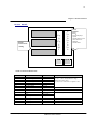
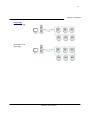
Topology
Loop Topology
Straight Line
Topology
DM323210,RD 6/2000
EPM420 Users Manual
28
Chapter 5--Installation
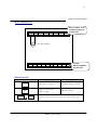
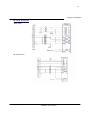
Wiring Diagram
3 wire 2 Delta
(2PT,2CT)
3W Direction
DM323210,RD 6/2000
EPM420 Users Manual
29
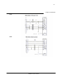
Chapter 5--Installation
3P3W
3P4W
DM323210,RD 6/2000
EPM420 Users Manual
30
Chapter 6--Maintenance/Troubleingshooting
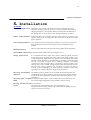
6. Maintenance/Troubleshooting
Preventive
maintenance
Cleaning the exterior of the instrument shall be limited to the wiping of the
instrument using a soft damp cloth applicator with cleaning agents that are
not alcohol based, and are nonflammable, non-explosive.
Troubleshooting
In this section, we bring up some poentail problems that you would like to
meet, and provide the check .or cure for these prblems.If,after completing
the listed checks,you still can’t solve the problem,connect the DAE
INSTRUMNET for assistance.
Problem :
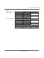
Possible Cause :
The EPM420 is not receiving the necessary power.
After applying
control power to the Check or Cure :
EPM420 ,the display Verify that EPM420 AC1 and AC2 terminal (terminal 25and 27)are receiving
the necessary power.
is still black.
Problem:
Possible Cause:
The data displayde is Incorrect setup values.
Check or Cure:
inaccurate or not
what you expected. Check to see that the correct value have been entered for EPM420 setup
parameter.(CT and PT rating,Wiring Type ,and so on.)See Programming your
meter in Chapter 4.
Possible Cause:
EPM420 is wired improperly.
Check or Cure:
Check the CTs and PTs are connceted correctly (proper polarity
observed.)and energized.Check shorting terminals.
Possible Cause:
Incorrect voltage input.
Check or Cure:
Check EPM420 voltage input terminals (terminals Va,Vb,Vc,Vn)to verify that
adequate voltage is present.
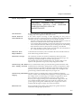
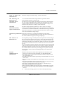
Problem:
Cannot communicte
with EPM420 from a
remote personal
computer.
Possible Cause:
EPM420 address is incorrect.
Check or Cure:
Check to see that EPM420 is correctly addressed.
Possible Cause:
EPM420 baud rate is incorrect.
Check or Cure:
Verify that the baud rate of EPM420 match the baud rate of all other devides
on it’s communications link.
Possible Cause:
DM323210,RD 6/2000
EPM420 Users Manual
Chapter 6--Maintenance/Troubleingshooting
31
Communicating lines are improperly biased.
Check or Cure:
Check to see that a multipoint communications link terminator is properly
installed.
DM323210,RD 6/2000
EPM420 Users Manual
32
Chapter 7--Appendix
7. Appendix
Drawings
Figure 7-1
Panel cutting
133
133
Unit : mm
Figure 7-2
Appearance
Unit : mm
DM323210,RD 6/2000
EPM420 Users Manual
33
Chapter 7--Appendix
B.
Communication protocol: (Modbus RTU protocol)
**EPM420 communication can has two 485 ports (optional, contact the factory)
B.1 Transmission mode
The mode of transmission is the structure of the individual units of
information within a message, and the numbering system used to
transmit the data. The mode is defined in the following, which is
compatible with Modbus RTU Mode*.
Table 7-1
Coding System
8-bit binary
Start bit
1
Data bits
8
Parity
no parity
Stop bit
1
Error checking
CRC check
B.2 Framing
Table 7-2
Address
Function
8-Bits
8-Bits
Message Frame Format Function Field
B.3
Function field
B.3.1 Function Codes
Table 7-3
Code
Meaning
01
Read DO Status
DM323210,RD 6/2000
02
Read DI
Status
03
Read Data
05
06
Control DO
Preset Single-Register
16
Preset
Multiple-Registers
EPM420 Users Manual
Data
N x 8-Bits
Check
16-Bits
Action
Obtain current status of
Digital Output
Obtain current status of
Digital Input
Obtain current binary value in
one or more registers
Force DO to a state of on or off
Place a specific binary value
into a Single-Register
Place specific binary values
into a series of consecutive
Multiple-Registers
34
Chapter 7--Appendix
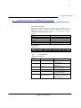
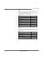
B.3.2
Read Data (Function Code 03)
Query
This function allows the user to obtain the measurements of EPM.
TABLE 3-2 is an example to read the 3 measured data (U1, U2 and U3)
from slave device number 17, the data address of U1 is 0000H, U2 is
0001H. And U3 is 0002H
Table 7-4
Address
11H
Function code
03H
Data start address high
00H
Data start address low
00H
Data register high
00H
Data register low
03H
CRC high
07H
CRC low
5BH
Table 3-2 Read UU1, U2, and U3 Query Message
Response
The EPM response includes the slave address, function code, quantity
of data characters, the data characters, and error checking. An
example response to read U1, U2 and U3 (U1=03E8H,
U2=03E7H,U3=03E9H) is shown as Table3-3
Table 7-5.
Address
11H
Function code
03H
Byte count
06H
Data register high
03H
Data register low
E8H
Data register high
03H
Data register low
E7H
Data register high
03H
Data register low
E9H
CRC high
FDH
CRC low
9CH
Table 3-3 Read U1, U2 andU3 Message
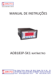
B.3.3 Preset / Reset Multi-Register (Function Code 16)
DM323210,RD 6/2000
EPM420 Users Manual
35
Chapter 7--Appendix
Query
Function 16 allows the user to modify the contents of a
Multi-Register. Any Multi Register that exists within the DPM can
have its contents changed by this message.
The example below is a request to slave number 17 to Preset
Ep+(178077833KWH), data address=0040H
Table 7-6
Address
11H
Function
10H
Data start register high
00H
Data start register low
40H
Data register high
00H
Data register low
02H
Byte count
04H
Value high
40H
Value low
89H
Value high
0AH
Value low
9DH
CRC high
A0H
CRC low
7CH
Table 3-4 Reset KWH Query Message
Response
The normal response to a preset Multi-Register request includes the
slave address, function code, data start reg, the number of regs,
and error checking.
Table 7-7
Address
11H
Function code
10H
Data start address high
00H
Data start address low
40H
Data register high
00H
Data register low
02H
CRC high
42H
CRC low
8CH
Table 3-5
Reset KWH+ Response Message
DM323210,RD 6/2000
EPM420 Users Manual
36
Chapter 7--Appendix
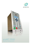
Energy Measurement
Table 7-8
Format: unsigned 16 bit
Funtion Code:03H
Base Address:40001
NAM DESCRIPIOTIO
ADDRESS
LENGTH FORMAT
E
N
Kwh total
0040H
(import)L
Ep+
4 bytes
F11
Kwh total
0041H
(import)H
Kvarh total
0044H
(import) L
4 bytes
Eq+
F11
Kvarh total
0045H
(import) H
Parameter Setting :
Table 7-9
Function code :16 ,
NAM DESCRIPIOTIO
ADDRESS
LENGTH FORMAT
E
N
wirin
0080H
3P3W or 3P4W
2 bytes
F6
g
Addre
0083H
RS485 address
2 bytes
F1
ss
Baud
0084H
Baud rate
2 bytes
F1
rate
0085H
PT
PTratio.
2 bytes
F7
0086H
CT
CTratio.
2 bytes
F8
DM323210,RD 6/2000
MIN
MAX
0
100000000
0.1Kwh
0
100000000
0.1Kwh
MIN
MAX
DEFAULT
0
1
0
0
31
0
0
4
4
0
0
31
31
0
0
EPM420 Users Manual
DEFAULT
UNIT
UNIT
Bps
37
Chapter 7--Appendix
Analog Measurement
Table 7-10
Funtion Code:03
NAM DESCRIPIOTIO
ADDRESS
LENGTH FORMAT
E
N
0000H
V1
Phase R volt
2 bytes
F6
0001H
V2
Phase S volt
2 bytes
F6
0002H
V3
Phase T volt
2 bytes
F6
0003H
V12
Line R-S volt
2 bytes
F6
0004H
V23
Line R-T volt
2 bytes
F6
0005H
V31
Line T-R volt
2 bytes
F6
0006H
I1
Phase R amp
2 bytes
F7
0007H
I2
Phase S amp
2 bytes
F7
0008H
I3
Phase T amp
2 bytes
F6
0009H
P
KW total
2 bytes
F8
000AH
Q
KVAR total
2 bytes
F8
000BH
S
KVA total
2 bytes
F8
000CH
f
Hz
2 bytes
F10
000DH
PF
PF
2 bytes
F9
DM323210,RD 6/2000
MIN
MAX
DEFAULT
UNIT
0
0
0
0
0
0
0
0
0
0
0
0
0
0
65535
65535
65535
65535
65535
65535
65535
65535
65535
65535
65535
65535
65535
65535
0
0
0
0
0
0
0
0
0
0
0
0
0
100
V
V
V
V
V
V
A
A
A
KW
KW
KW
EPM420 Users Manual
%
38
Parameter reading
Table 7-11
Function Code:03
NAM
ADDRESS
E
wirin
0080H
g
0081H
PT
0082H
CT
Addre
0083H
ss
Baud
0084H
rate
DM323210,RD 6/2000
DESCRIPIOTIO
LENGTH FORMAT
N
MIN
MAX
DEFAULT
3P3W or 3P4W
2 bytes
F1
0
1
0
PT index NO.
CT index NO.
2 bytes
2 bytes
F2
F3
0
0
32
32
0
0
RS485 address
2 bytes
F4
0
31
0
Baud rate
2 bytes
F5
0
4
4
EPM420 Users Manual
UNIT
Bps
39
Chapter 7--Appendix
Format Table
Table 7-12
Format NO.
Format Type
Format Definition
F1
Wiring table
1:for 3P3W ; 0: for 3P4W
F4
F5
F6
F7
F8
RS485 address
Baud rate index NO.
Voltage
Current
Power(P,Q,S demand)
F9
PF
F10
F11
Hz
Energy
DM323210,RD 6/2000
0 :1200,1:2400,2:4800,3:9600,4:19200
Data/10 x PT ratio
Data/1000 x CT ratio
p= data x PT ratio x CT ratio(w)
positive:Data/100
negative: (Data - 65535) / 100
Data/10
{Word(h) x 65536 + word(L) } /10
EPM420 Users Manual