1
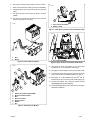
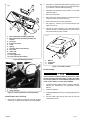
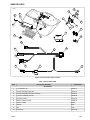
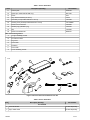
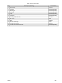
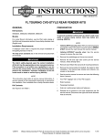
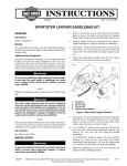
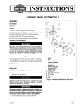
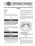
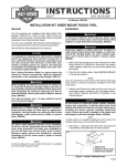
-J04427
REV. 2007-12-04
POWER LOCK KIT
GENERAL
Kit Number
2.
See Figure 1. Remove lid (1) and hinge (2) from saddlebag.
3.
Remove lock (3) from saddlebag.
4.
See Figure 2. Set drill template on hinge surface of the
saddlebag aligning the template (5) with hinge mounting
holes (7).
5.
See Figure 3. Drill 0.344 (11/32) inch diameter hole (1).
6.
Place the template on the back of the saddlebag (4)
aligning front mounting grommet (2) and forward latch
bracket (1).
7.
See Figure 4. Drill 0.500-0.515 inch diameter hole (1).
8.
Repeat on the other saddlebag.
76463-08, 76510-08
Models
For model fitment information, please see the P&A Retail Catalog or the Parts and Accessories section of www.harleydavidson.com (English only).
Additional Parts Required
The rider's safety depends upon the correct installation
of this kit. Use the appropriate service manual procedures.
If the procedure is not within your capabilities or you do
not have the correct tools, have a Harley-Davidson dealer
perform the installation. Improper installation of this kit
could result in death or serious injury. (00333a)
is04988
1
NOTE
This instruction sheet references Service Manual information.
A Service Manual for your model motorcycle is required for
this installation and is available from a Harley-Davidson Dealer.
Kit Contents
See Figure 12 and Table 1 and Figure 13 and Table 2.
INSTALLATION
2
To prevent accidental vehicle start-up, which could cause
death or serious injury, disconnect negative (-) battery
cable before proceeding. (00048a)
3
Disconnect negative (-) battery cable first. If positive (+)
cable should contact ground with negative (-) cable connected, the resulting sparks can cause a battery explosion,
which could result in death or serious injury. (00049a)
1.
Disconnect the battery, negative (-) battery cable first,
following the instructions in the appropriate Service
Manual.
2.
Remove seat following the instructions in the appropriate
Service Manual.
1. Saddlebag lid
2. Saddlebag hinge
3. Saddlebag lock
Figure 1. Remove Lid, Hinge and Lock from Saddlebag
Preparing the Saddlebags for Power Locks
1.
Remove saddlebags following the instructions in the
appropriate Service Manual.
-J04427
1 of 7
NOTE
See Figure 9. There are two actuator assemblies, a left side
(2) and a right side (1). If the actuator cable does not lay against
the hinge wall of the saddlebag, use the other actuator.
is04985
1
2
4
2.
Install actuator (1) into bottom back corner of saddlebag.
Peel off the backing from the double-sided tape on bottom
of actuator before positioning into saddlebag. The cable
from the actuator should be tight against the hinge-side
wall of the saddlebag.
3.
Align the cam plate with the 0.344 hole (previously drilled).
Install two inner screws to face plate (10) of the lid/hinge.
Tighten finger-tight.
4.
Push the outer cam (9) through the hole in the saddlebag
and cam plate. Align the inner cam (8) to the square stock
of the outer cam.
5.
Slide the small end of the spring (6) over the square stock
of the outer cam (9). Press the spring in place with the
spacer (4).
6.
Secure the assembly with the E-clip (5).
7.
Attach the cable barrel to the cam arm and tighten the
locknut on the cable end.
8.
Tighten the two inner screws to 25 in-lbs (2.8 Nm).
9.
Install cover (11) over the cam assembly. Install the lid
tether on the back of the cover (11). Install screws (3).
Tighten the screws only to the point where the tether fabric
just begins to wrinkle.
3
5
6
7
1. Forward latch bracket position
2. Mounting grommet position
3. Drill 0.5-0.515 inch diameter hole in saddlebag
back
4. Saddlebag back
5. Saddlebag hinge side
6. Drill 0.344 inch diameter hole in hinge area
7. Rear hinge mounting hole
Figure 2. Drilling Template
is05189
1
10. Install strain relief bushing (7) into the 0.50 hole (previously
drilled). Install the actuator cable into the strain relief
bushing.
11. Install the self-adhesive clips to hold wire against side of
the saddlebag.
12. Install the 2-way housing (16) onto the ends of the actuator
wires and secure with the secondary lock.
1. 0.344 inch diameter hole
Figure 3. Drill Hole in Saddlebag Front
13. Repeat Steps 1-12 for the other saddlebag.
NOTE
Saddlebag liners (88235-07, right and 88236-07, left) are
available from your Harley-Davidson dealer.
is05188
Install Receiver Module and Wire Harness
2
1.
Remove right side cover.
2.
See Figure 5. Remove bolt (1) and spacer (2) holding arm
of battery caddy.
3.
See Figure 6.
1
For Models without ABS: Install receiver bracket (2) and
spacer (1) to the caddy with bolt (3).
For Models with ABS: Install receiver bracket (2) to the
caddy with bolt (3). Spacer (1) can be discarded.
1. 0.500-0.515 inch diameter hole
2. Grommet
Figure 4. Drill Hole in Saddlebag Back
Installing Power Lock in Saddlebags
1.
See Figure 12. Install new lock (1) on saddlebag hinge.
Tighten to 30-40 in-lbs (41-54 Nm).
-J04427
4.
Tighten screw to 72-96 in-lbs (8-11 Nm).
NOTE
See Figure 7. Ensure the foot (1) of the receiver bracket hook
onto the arm of the battery caddy (2).
5.
See Figure 6. Install receiver module (4) onto receiver
module bracket (2) with rubber washer (5), washer (6) and
nut (7). Tighten nut to 20-40 in-lbs (2.3-4.5 Nm).
2 of 7
6.
See Figure 12. Plug connector (B) into receiver module.
7.
Route connector wires (C and E) up the front of the battery.
8.
Install ground wire (C) onto ground stud on the motorcycle
frame.
9.
See Figure 8. Plug connector (E) into the B+ connector
[160B].
is05198
1
10. See Figure 12. Route wire (A) between frame and rear
fender on right side of motorcycle.
2
is04997
1. Foot of receiver bracket
2. Battery caddy
Figure 7. Install Receiver Bracket onto the Battery Caddy
is05190
2
1
1
1. Bolt
2. Spacer
1. B+ connector [160B]
Figure 5. Remove Bolt and Spacer
is04998
Figure 8. Upper Frame Crossmember (Under Seat)
11. See Figure 10. Push clip fastener (1) into frame hole
located in front of shock absorber mounting (2).
1
12. See Figure 12. Route wires (F and G) over the rear fender.
3
13. Connect the two-pin connector (G) to the frame on the left
side in front of the shock absorber (Figure 10, Item 2).
14. See Figure 12. If not installing the Tour-Pak® lock kit:
Install the three-pin connector (F) with weather plug (18).
2
5
6
7
1.
2.
3.
4.
5.
6.
7.
4
15. Connect the actuator wire connectors exiting the saddlebag before locking the saddlebag.
16. Install saddlebags following the instructions in the appropriate Service Manual.
Spacer (for models without ABS)
Receiver module bracket
Bolt
Receiver module
Rubber washer
Washer
Nut
Figure 6. Install Receiver Module
-J04427
3 of 7
is04996
9
10
8
4
6
See Figure 13. Install Tour-Pak actuator assembly (1) into
lid of Tour-Pak. Remove backing from double-sided tape
(2) on bottom of actuator before positioning.
3.
Assemble lock components using washer, nut and lock
guide from Step 1.
4.
Remove Tour-Pak liner.
5.
Route wires from actuator across the inside top of lid to
hinge area. Hold in place with clips (12).
6.
Route wires down into the Tour-Pak bottom.
7.
See Figure 12. Connect (F) to Tour-Pak harness (see
Figure 13, Item 13).
8.
Connect the 2-way connector to the Tour-Pak harness
after the harness is routed inside the Tour-Pak. Connect
the Tour-Pak harness to the actuator.
1
2
5
7
3
2.
11
12
is05179
1. Box and actuator assembly (right side)
2. Box and actuator assembly (left side) (not
shown)
3. Screw (2)
4. Power lock spacer
5. E-clip
6. Spring
7. Cord grip strain relief bushing
8. Inner cam
9. Outer cam
10. Face plate
11. Cover (right side)
12. Cover (left side) (not shown)
3
2
1
Figure 9. Saddlebag Assembly
1. Washer
2. Lock guide
3. Locknut
is05183
Figure 11. Tour-Pak Lock Set
Final Assembly
2
1
1.
1. Clip fastener
2. Shock absorber
Connect the battery cables, positive (+) battery cable first,
following the instructions in the appropriate Service
Manual.
2.
Install Tour-Pak liner.
3.
Install seat following instructions in the appropriate Service
Manual.
4.
Test the power locks with key fob. Press the lock and
unlock buttons to test.
Figure 10. Install Clip Fastener (Left Side Shown)
Install Power Lock in Tour-Pak
1.
Connect positive (+) battery cable first. If positive (+) cable
should contact ground with negative (-) cable connected,
the resulting sparks can cause a battery explosion, which
could result in death or serious injury. (00068a)
See Figure 11. Remove lock set from Tour-Pak lid. Save
washer (1), lock guide (2) and locknut (3) for re-installation.
-J04427
4 of 7
SERVICE PARTS
is04989
12
13
2
15
3
8
6
16
20
9
5
7
10
11
1
4
19
A
G
17
B
18
F
E
D
C
Figure 12. Service Parts: Power Lock Kit
Table 1. Service Parts Table
Item
Description (Quantity)
Part Number
Kit 76463-08
1
Lock assembly (2)
53986-07
2
Actuator assembly, right side
79163-07
3
Actuator assembly, left side (not shown)
79156-07
4
Harness, saddlebag actuator
76458-08
5
Receiver module
76524-08
6
Bracket, receiver module
76528-08
7
Washer, rubber
6035A
8
Washer
6036
9
Nut
7499
10
Key fob (2)
76543-08
-J04427
5 of 7
Table 1. Service Parts Table
Item
Description (Quantity)
Part Number
11
Drill template
94093-08
12
Spacer (for models without ABS only)
90175-00
13
Screw
3277
14
Clip, adhesive-backed (not shown)
10102
15
Secondary lock (included with items 1 and 2)
74152-98
16
Housing, 2-way socket (included with items 1 and 2)
74112-98BK
17
Power lock wire harness
76458-08
18
Weather plug (installed in [F])
72163-94
19
Clip
73198-96
20
Power lock hardware kit
88283-07
Wire Harness Designations
A
To right saddlebag module
B
To receiver module
C
To ground
D
Fuse holder
E
To battery
F
To Tour-Pak
G
To left saddlebag module
is04999
A
3
12
1
5
2
7
8
4
9
6
10
13
11
Figure 13. Service Parts: Tour-Pak Power Lock Kit
Table 2. Service Parts Table
Item
Description (Quantity)
Part Number
Kit 76510-08
1
Tour-Pak actuator
Not Sold Separately
2
Tape, double-sided
Not Sold Separately
-J04427
6 of 7
Table 2. Service Parts Table
Item
Description (Quantity)
Part Number
3
Cable bracket
79135-08
4
Lock stop
Not Sold Separately
5
Retaining pin
Not Sold Separately
6
Lock hook
Not Sold Separately
7
E-clip
Not Sold Separately
8
Lock driver
Not Sold Separately
9
Tour-Pak power lock cover
79171-08
10 Cap screw
2478
11 Catch
79182-08
12 Adhesive-backed clip
10102
13 Tour-Pak wire harness
76481-08
A
Not Sold Separately
Tour-Pak wire harness connector
-J04427
7 of 7