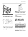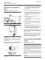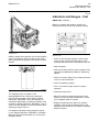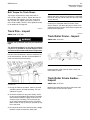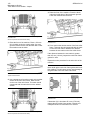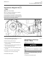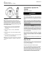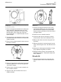
1
MAINTENANCE INTERVALS
Operation and Maintenance
Manual Excerpt
© 2010 Caterpillar
All Rights Reserved
®
®
SEBU8031-04
August 2009
Operation and
Maintenance
Manual
587T Pipelayer
FAT1-Up (587T)
SAFETY.CAT.COM
106
Maintenance Section
Maintenance Interval Schedule
SEBU8031-04
i03487001
Maintenance Interval Schedule
SMCS Code: 7000
Ensure that all safety information, warnings and
instructions are read and understood before any
operation or any maintenance procedures are
performed.
The user is responsible for the performance of
maintenance, including all adjustments, the use of
proper lubricants, fluids, filters, and the replacement
of components due to normal wear and aging. Failure
to adhere to proper maintenance intervals and
procedures may result in diminished performance of
the product and/or accelerated wear of components.
Cooling System Coolant Level - Check ............... 116
Counterweight Cylinder Bearings - Lubricate ..... 120
Counterweight Hinge Pins - Lubricate ................ 120
Engine Oil Level - Check .................................... 123
Fairlead Sheave - Lubricate ................................ 128
Fuel System Water Separator - Drain ................. 132
Hook and Wire Cable - Inspect ........................... 136
Horn - Test .......................................................... 138
Hydraulic System Oil Level - Check ................... 142
Indicators and Gauges - Test .............................. 143
Seat Belt - Inspect .............................................. 147
Transmission System Oil Level - Check ............. 157
Every 50 Service Hours or Weekly
Cab Filter (Fresh Air) - Clean/Inspect/Replace .... 113
Sheave Block Bearings - Lubricate ..................... 148
Track Pins - Inspect ............................................ 151
Use mileage, fuel consumption, service hours, or
calendar time, WHICH EVER OCCURS FIRST,
in order to determine the maintenance intervals.
Products that operate in severe operating conditions
may require more frequent maintenance.
Initial 250 Service Hours
Note: Before each consecutive interval is performed,
all maintenance from the previous interval must be
performed.
Every 250 Service Hours
Note: If Cat HYDO Advanced 10 hydraulic oil is
used, the hydraulic oil change interval will change.
The normal interval of 2000 hours is extended to
3000 hours. S·O·S services may extend the oil
change even longer. Consult your Caterpillar dealer
for details.
When Required
Air Conditioner Condenser - Clean ..................... 108
Battery - Recycle ................................................ 109
Battery or Battery Cable - Replace ..................... 109
Boom Line - Install ............................................... 110
Engine Air Filter Primary Element - Clean/
Replace ............................................................. 121
Engine Air Filter Secondary Element - Replace .. 122
Engine Air Precleaner - Clean ............................ 122
Ether Starting Aid Cylinder - Replace ................. 127
Fuel System - Prime ........................................... 130
Fuses and Circuit Breakers - Replace/Reset ...... 135
Hook Load Line - Install ...................................... 137
Oil Filter - Inspect ................................................ 144
Radiator Core - Clean ......................................... 144
Radiator Pressure Cap - Clean/Replace ............ 144
Window Washer Reservoir - Fill .......................... 161
Window Wipers - Inspect/Replace ...................... 162
Windows - Clean ................................................. 162
Every 10 Service Hours or Daily
Backup Alarm - Test ............................................ 108
Boom Pivot Pins - Lubricate ................................ 112
Braking System - Test .......................................... 112
Engine Valve Lash - Check ................................. 126
Engine Valve Rotators - Inspect ......................... 127
Winch Oil - Change ............................................. 160
Engine Oil Sample - Obtain ................................ 124
Winch Frame Mounting - Inspect ........................ 160
Every 250 Service Hours or Monthly
Final Drive Oil Level - Check ..............................
Fuel Tank Water and Sediment - Drain ...............
Track - Check/Adjust ...........................................
Winch Oil Level - Check .....................................
129
134
149
161
Every 250 Service Hours or 3 Months
Belt - Inspect/Replace ......................................... 109
Initial 500 Hours (for New Systems, Refilled
Systems, and Converted Systems)
Cooling System Coolant Sample (Level 2) Obtain ................................................................ 119
Every 500 Service Hours
Final Drive Oil Sample - Obtain .......................... 129
Hydraulic System Oil Sample - Obtain ............... 142
Every 500 Service Hours or 3 Months
Cooling System Coolant Sample (Level 1) Obtain ................................................................ 117
Engine Crankcase Breather - Clean ................... 123
Engine Oil and Filter - Change ........................... 125
Fuel System Secondary Filter - Replace ............ 131
Fuel System Water Separator Element Replace ............................................................. 132
Fuel Tank Cap and Strainer - Clean ................... 134
Recoil Spring Compartment Oil Level - Check ... 145
SEBU8031-04
107
Maintenance Section
Maintenance Interval Schedule
Steering Charge Filter - Replace ........................ 148
Transmission System Oil Filter - Replace ........... 156
Transmission System Oil Sample - Obtain ......... 158
Every 500 Service Hours or 1 Year
Winch Oil - Change ............................................. 160
Every 1000 Service Hours
Battery - Inspect .................................................. 109
Every 1000 Service Hours or 6 Months
Rollover Protective Structure (ROPS) - Inspect ..
Torque Converter Scavenge Screen - Clean ......
Transmission Magnetic Screen - Clean ..............
Transmission Scavenge Screen - Clean .............
Transmission System Oil - Change ....................
147
149
153
153
154
Every 2000 Service Hours
Engine Valve Lash - Check ................................. 126
Engine Valve Rotators - Inspect ......................... 127
Every 2000 Service Hours or 1 Year
Air Conditioner Condenser - Clean .....................
Final Drive Oil - Change .....................................
Hydraulic System Oil - Change ...........................
Hydraulic System Oil Filters - Replace ...............
Track Roller Frame - Inspect ..............................
Track Roller Frame Guides - Inspect ..................
108
128
138
141
151
151
Every Year
Cooling System Coolant Sample (Level 2) Obtain ................................................................ 119
Refrigerant Dryer - Replace ................................ 146
Every 3 Years After Date of Installation or
Every 5 Years After Date of Manufacture
Seat Belt - Replace ............................................. 148
Every 6000 Service Hours or 3 Years
Cooling System Coolant Extender (ELC) - Add ... 115
Cooling System Water Temperature Regulator Clean/Replace ................................................... 119
Every 8000 Service Hours or 3 Years
Winch Assembly - Inspect .................................. 159
Every 12 000 Service Hours or 6 Years
Cooling System Coolant (ELC) - Change ............ 113
108
Maintenance Section
Air Conditioner Condenser - Clean
SEBU8031-04
i02455837
Air Conditioner Condenser Clean
SMCS Code: 1805-070
Illustration 137
g01427275
1. Remove the cover for the condenser.
2. Inspect the condenser for debris. Clean the
condenser, if necessary.
Illustration 136
g01225616
The air conditioner condenser is located behind the
radiator.
3. Use clean water to wash all of the dust and dirt
from the condenser.
4. Install the cover for the condenser.
Open the left engine access door.
i02486464
Inspect the air conditioner condenser for the following
conditions:
Backup Alarm - Test
• Damaged fins
SMCS Code: 7406-081
• Buildup of debris
• Plugged areas
Remove any debris. Clean the condenser with low
pressure air or low pressure water.
i02865300
Air Conditioner Condenser Clean
SMCS Code: 1805-070
Illustration 138
NOTICE
If excessively dirty, clean condenser with a brush. To
prevent damage or bending of the fins, do not use a
stiff brush.
Repair the fins if found defective.
g01249997
In order to test the alarm for proper functioning, turn
engine start switch (1) to the ON position.
Apply service brake (2). Disengage parking brake
switch (4). Move transmission direction selector (3)
to the REVERSE position.
The backup alarm should start to sound immediately.
The alarm alerts the personnel behind the machine
that the machine is backing up. The alarm will
continue to sound until transmission direction selector
(3) is moved to the NEUTRAL position or to the
FORWARD position.
SEBU8031-04
109
Maintenance Section
Battery - Inspect
• Recycling facility
i01926166
Battery or Battery Cable Replace
SMCS Code: 1401-510; 1401; 1402-510
1. Turn the engine start switch key to the OFF
position. Turn all of the switches to the OFF
position.
Illustration 139
g01241595
2. Turn the battery disconnect switch to the OFF
position. Remove the key.
Typical example
The backup alarm is on the rear of the machine. The
nonadjustable backup alarm is set at the appropriate
sound level when the machine is shipped from the
factory.
i02486605
Battery - Inspect
Tighten the battery retainers on all batteries at every
1000 hour interval.
Perform the following procedures at every 1000 hour
interval. Check these areas more often, if necessary.
1. Open the battery access cover. The battery access
cover is located on the left side or right side of the
machine next to the operator's compartment.
2. Clean the top of the batteries with a clean
cloth. Keep the terminals clean and coated with
petroleum jelly. Install the terminal covers after
you coat the terminals.
5. Make necessary repairs or replace the battery.
7. Connect the battery cable at the battery disconnect
switch.
8. Install the key and turn the battery disconnect
switch to the ON position.
i03656921
Belt - Inspect/Replace
SMCS Code: 1357-040; 1357-510
Your engine is equipped with a serpentine belt that
drives the alternator.
This engine is equipped with a belt tightener that
automatically adjusts the belt to the correct tension.
3. Close the battery access cover.
i00993589
Battery - Recycle
SMCS Code: 1401-561
Always recycle a battery. Never discard a battery.
Always return used batteries to one of the following
locations:
• An authorized battery collection facility
4. Disconnect the negative battery cable at the
battery.
6. Connect the negative battery cable at the battery.
SMCS Code: 1401-040
• A battery supplier
3. Disconnect the battery cable at the battery
disconnect switch. The battery disconnect switch
is connected to the machine frame.
Inspect
1. Park the machine on level ground. Move the
transmission control to the NEUTRAL position and
engage the parking brake. Shut off the engine.
Note: Before you service the pipelayer, make sure
that the counterweight frame is fastened in the
retracted position.
2. Turn the battery disconnect switch to the OFF
position.
3. Open the access door on the right side of the
machine.
110
Maintenance Section
Boom Line - Install
SEBU8031-04
5. The belt should deflect 14 to 20 mm (.56 to .81 inch)
under 110 N (25 lb) of force. Use a 144-0235 Belt
Tension Gauge in order to measure the tension.
6. Close the engine access doors.
7. Turn the battery disconnect switch to the ON
position.
Replace
Note: If a new belt is installed, check the belt
adjustment (drive belt tension) again after 30 minutes
of engine operation.
Replace
1. Park the machine on level ground. Move the
transmission control to the NEUTRAL position and
engage the parking brake. Shut off the engine.
Illustration 140
g01323939
Alternator only
Note: Before you service the pipelayer, make sure
that the counterweight frame is fastened in the
retracted position.
2. Turn the battery disconnect switch to the OFF
position.
3. Open the engine access doors.
4. Turn belt tensioner (1) in order to release the
tension from the belt with a square drive.
5. Remove serpentine belt (4).
6. Install the new serpentine belt.
7. Close the engine access doors.
8. Turn the battery disconnect switch to the ON
position.
i02640261
Illustration 141
g01017579
Boom Line - Install
A/C Compressor
(1)
(2)
(3)
(4)
(5)
(6)
Belt tensioner
Alternator
Compressor
Serpentine belt
Idler pulley
Alternator guard
4. Inspect the condition of serpentine belt (4).
Replace the serpentine belt if excessive wear or
cracking has occurred. Wear due to belt slippage
indicates that the belt tensioner possibly needs
to be replaced.
SMCS Code: 6301-012-LI
Reference: Service Magazine, “New Boom Upper
Sheave Block Improves cable Spooling” 1 June 1999.
SEBU8031-04
111
Maintenance Section
Boom Line - Install
Do not operate or work on this equipment unless
you have read and understand the instructions
and warnings in the Operation and Maintenance
Manual. Failure to follow the instructions or heed
the warnings could result in injury or death. Contact any Caterpillar dealer for replacement manuals. Proper care is your responsibility.
Do not use a wire rope cable that is kinked, frayed
or has worn spots.
Wear gloves when handling the wire rope cable.
NOTICE
Use 9 strand wire rope of right regular lay, pre-formed
Bridon Constuctex cable. The wire rope cable should
have a minimum breaking strength of 33112 kg
(73000 lb).
Illustration 142
g01242135
5. Wind one half of the wire cable on the drum. Wind
the cable evenly across the drum.
6. Install wire cable end (9) in the drum. To hold the
wire cable end in place, install the bolts and cable
clamp (8).
Table 10
Specifications for Boom Line
Boom Height
8534 mm (28 ft)
Cable Size
(Diameter)
19.05 mm (.75
inch)
Length
62.5 m (205 ft)
1. Lower the boom to the ground and support the
boom.
Note: The loaded force in the winch drum must
be neutralized before removing the wire rope
from a loaded drum.
Reference: Refer to “Winch Wire Rope - Remove
and Install” in this manual for the information in
order to safely remove the wire rope from winch
drums, if necessary.
2. Remove the anchor for the wire rope from the
drum for the boom.
NOTICE
Unroll the wire rope cable from the spool. Never lift the
wire rope off the spool in coils.
3. Unroll the new wire rope from the spool.
Note: Weld the wire cable ends in order to prevent
fraying.
4. Install the ferrule of the wire rope to the drum for
the boom.
Illustration 143
g01242133
112
Maintenance Section
Boom Pivot Pins - Lubricate
SEBU8031-04
13. Raise the boom.
i02487567
Boom Pivot Pins - Lubricate
SMCS Code: 6301-086-PN
The grease fittings for lubricating the boom pivot pins
are located on the left side of the machine. There is
one grease fitting for each pin. The grease fittings
are located on the end of the pin on the outside face
of the boom.
Illustration 144
g01242134
Illustration 145
g01242204
View from the rear of the machine
7. Install wire rope (7) over sheave assembly (1) in
the upper sheave block.
Note: Install wire rope (7) over sheave assembly (1)
from the front of the machine toward the rear of the
machine.
8. Install the wire rope under sheave assembly (3) in
the lower sheave block.
9. Install the wire rope over sheave assembly (2) in
the upper sheave block.
10. Install the wire rope under sheave assembly (4)
in the lower sheave block.
Lubricate the boom pivot pins through the two grease
fittings.
i01958206
Braking System - Test
SMCS Code: 4100-081; 4267-081
If the machine moves during the test, reduce the
engine speed immediately, and engage the parking brake.
11. Insert the wire rope into the pocket and around
wedge (5). Use a mallet to tap wedge (5) and the
cable into the pocket.
If the machine moved while testing the brakes,
consult your Caterpillar dealer for brake inspection and repair. Damaged brakes must be repaired
before returning the machine to operation.
12. Insert the end of the cable through clamp (6).
Tighten the setscrew in the clamp to a torque of
45 ± 7 N·m (33 ± 5 lb ft).
Note: The machine can drive through the brakes
in first gear.
SEBU8031-04
113
Maintenance Section
Cab Filter (Fresh Air) - Clean/Inspect/Replace
Make sure that the area around the machine is clear
of personnel and clear of obstacles.
Test the brakes on a dry, level surface.
Fasten the seat belt before you test the brakes.
1. Start the engine.
2. Raise all attachments.
Note: Clean the filters more often in dusty conditions.
1. Remove the filter cover and the filter element.
The filter cover is inside the cab to the left of the
operator seat.
2. The filter element can be cleaned by using
pressure air. Use a maximum air pressure of
205 kPa (30 psi). Direct the air from the clean side
to the dirty side.
3. Look through the filter toward a bright light. Inspect
the element for damage. Inspect the gaskets for
damage. Replace damaged filters.
4. Install the filter element.
i02489152
Cooling System Coolant (ELC)
- Change
SMCS Code: 1395-044
Illustration 146
g01017767
3. Depress the brake pedal.
4. Release the parking brake.
5. While the brake pedal is depressed, move the
directional control to the SECOND SPEED
FORWARD position.
6. Gradually increase the engine speed to full load
speed. The machine should not move.
7. Move the directional control to the NEUTRAL
position.
8. Reduce the engine speed to LOW IDLE. Engage
the parking brake. Lower all attachments to the
ground. Apply a slight down pressure. Stop the
engine.
NOTICE
If the machine moved while testing the brakes, contact
your Caterpillar dealer. Have the dealer inspect and,
if necessary, repair the service brake before returning
the machine to operation.
i02455960
Cab Filter (Fresh Air) Clean/Inspect/Replace
SMCS Code: 7342-510; 7342-571
if equipped:
For information about adding an extender to your
cooling system, see the Topic “Cooling System
Coolant Extender (ELC) - Add” in this manual or
consult your Caterpillar dealer.
NOTICE
Care must be taken to ensure that fluids are contained
during performance of inspection, maintenance, testing, adjusting and repair of the product. Be prepared to
collect the fluid with suitable containers before opening any compartment or disassembling any component containing fluids.
Refer to Special Publication, NENG2500, “Caterpillar
Dealer Service Tool Catalog” for tools and supplies
suitable to collect and contain fluids on Caterpillar
products.
Dispose of all fluids according to local regulations and
mandates.
To Drain the Cooling System
The filler cap is located inside the access door on the
top of the radiator guard.
114
Maintenance Section
Cooling System Coolant (ELC) - Change
SEBU8031-04
2. The two drain valves for coolant are located
under the radiator and the front bottom end of the
engine. Remove front bottom guard (3) in order to
drain the coolant.
3. Direct the drain hoses into suitable containers.
Illustration 147
g01243263
Illustration 149
g01017961
4. Open the drain valves. Allow the coolant to drain
into a suitable container.
Personal injury can result from hot coolant, steam
and alkali.
5. Flush the system with water. Flush the system
until the draining water is clear.
At operating temperature, engine coolant is hot
and under pressure. The radiator and all lines
to heaters or the engine contain hot coolant or
steam. Any contact can cause severe burns.
Note: If the cooling system is already using ELC,
cleaning agents are not required to be used at
the specified coolant change interval. Cleaning
agents are only required if the system has been
contaminated by the addition of some other type of
coolant or by cooling system damage. Clean water is
the only cleaning agent that is required when ELC is
drained from the cooling system.
Remove filler cap slowly to relieve pressure only
when engine is stopped and radiator cap is cool
enough to touch with your bare hand.
Cooling System Conditioner contains alkali. Avoid
contact with skin and eyes.
1. Slowly loosen filler cap (1) in order to relieve
system pressure. Remove the filler cap.
Note: If you change to an ELC from another type of
coolant, use a Caterpillar cleaning agent to flush the
cooling system. After you drain the cooling system,
thoroughly flush the cooling system with clean water.
All of the cleaning agent must be removed from
the cooling system..
6. Close the drain valves and install the plug.
7. Replace front bottom guard (3).
8. Add the ELC solution. See the following topics in
this publication:
• Capacities (Refill)
Illustration 148
Top view
g01243455
Note: Caterpillar antifreeze contains additive. If
you are using Caterpillar antifreeze, do not add the
supplemental coolant additive at this time. Also,
do not change the supplemental coolant additive
element at this time.
SEBU8031-04
115
Maintenance Section
Cooling System Coolant Extender (ELC) - Add
9. Start the engine. Run the engine without the filler
cap until the thermostat opens and the coolant
level stabilizes.
i03499306
Cooling System Coolant
Extender (ELC) - Add
SMCS Code: 1395-538
NOTICE
Care must be taken to ensure that fluids are contained
during performance of inspection, maintenance, testing, adjusting and repair of the product. Be prepared to
collect the fluid with suitable containers before opening any compartment or disassembling any component containing fluids.
Illustration 150
g01239290
10. Open left engine access door (2). Look into the
sight glass. Maintain the coolant level above the
height of the sight glass at minimum. No air should
be visible in the sight glass. Add coolant to the
filler tube, if necessary.
11. If the gasket is damaged, replace filler cap (1).
Install the filler cap.
Refer to Special Publication, NENG2500, “Caterpillar
Dealer Service Tool Catalog” for tools and supplies
suitable to collect and contain fluids on Caterpillar
products.
Dispose of all fluids according to local regulations and
mandates.
Table 11
“Cat ELC Extender” and the Cooling System Capacity
Cooling System Capacity
12. Stop the engine.
Recommended
Amount of “Cat
ELC Extender”
75 L (19.8 US gal)
1.5 L (52 fl oz)
84 L to 114 L (22 to 30 US gal)
2.15 L (72 fl oz)
When a Caterpillar Extended Life Coolant (ELC)
is used, an extender must be added to the cooling
system. See the Operation and Maintenance
Manual, “Maintenance Interval Schedule” for the
proper service interval. The amount of extender is
determined by the cooling system capacity.
Illustration 151
g01117259
13. Clean the radiator cores with compressed air. You
may need to use water in order to remove debris.
14. Close the engine access door.
For additional information about the cooling
system coolant, see Operation and Maintenance
Manual, SEBU6250, “Caterpillar Machine Fluids
Recommendations”, “Cat Extended Life Coolant
(ELC)” or consult your Caterpillar dealer.
For additional information about adding an extender,
see Special Publication, SEBU6250, “Caterpillar
Machine Fluids Recommendations” or consult your
Caterpillar dealer.
Extended Life Coolant (ELC)
Extender
Use a 8T-5296 Coolant Conditioner Test Kit to
check the concentration of the coolant.
116
Maintenance Section
Cooling System Coolant Level - Check
SEBU8031-04
3. Add 2.15 L (72 oz) of Extender to the cooling
system for the 583T Pipelayer.
Personal injury can result from hot coolant, steam
and alkali.
At operating temperature, engine coolant is hot
and under pressure. The radiator and all lines
to heaters or the engine contain hot coolant or
steam. Any contact can cause severe burns.
4. Add 1.5 L (52 oz) of Extender to the cooling system
for the 587T Pipelayer or the 587R Pipelayer.
5. Start the engine. Run the engine without the filler
cap until the thermostat opens and the coolant
level stabilizes. Check for leaks.
Remove filler cap slowly to relieve pressure only
when engine is stopped and radiator cap is cool
enough to touch with your bare hand.
Cooling System Conditioner contains alkali. Avoid
contact with skin and eyes.
Illustration 153
g01243042
6. Open the left engine access door. Look into the
sight glass. Maintain the coolant level above the
height of the sight glass at minimum. No air should
be visible in the sight glass. Add coolant to the
filler tube, if necessary.
Illustration 152
g01835526
1. The filler cap is located inside the access door on
the top, left side of the radiator guard. Loosen the
radiator cap slowly in order to relieve pressure.
Remove the radiator cap.
7. Replace the radiator cap if the cap gasket is
damaged. Install the radiator cap.
8. Stop the engine.
i02488942
2. It may be necessary to drain some coolant from
the radiator so that Extender can be added to the
cooling system.
Cooling System Coolant Level
- Check
Note: Always discard drained fluids according to
local regulations.
SMCS Code: 1353-535-FLV; 1395-535-FLV
NOTICE
Care must be taken to ensure that fluids are contained
during performance of inspection, maintenance, testing, adjusting and repair of the machine. Be prepared
to collect the fluid with suitable containers before
opening any compartment or disassembling any component containing fluids.
Refer to Special Publication, NENG2500, “Caterpillar
Tools and Shop Products Guide”, for tools and supplies suitable to collect and contain fluids in Caterpillar
machines.
Dispose of all fluids according to local regulations and
mandates.
The cooling system pressure cap is under the access
cover on the top, left side for the radiator guard.
SEBU8031-04
117
Maintenance Section
Cooling System Coolant Sample (Level 1) - Obtain
Illustration 156
g01117259
4. Inspect the radiator core for debris. clean the
radiator core, if necessary.
Illustration 154
g01242972
1. Open radiator access door (1). Remove the
cooling system pressure cap slowly in order to
relieve the pressure.
Use compressed air, high pressure water, or
steam to remove dust and debris from the radiator
core. However, the use of compressed air is
preferred.
5. Close the engine access door.
i02111226
Cooling System Coolant
Sample (Level 1) - Obtain
SMCS Code: 1350-008; 1395-008; 1395-554;
7542-008; 7542
Illustration 155
g01239290
2. Open left engine access door (2). Look into the
sight glass. Maintain the coolant level above the
height of the sight glass at minimum. No air should
be visible in the sight glass. If it is necessary to
add coolant daily, check the system for leaks.
3. Install the cooling system pressure cap. Close the
radiator access door.
NOTICE
Always use a designated pump for oil sampling, and
use a separate designated pump for coolant sampling.
Using the same pump for both types of samples may
contaminate the samples that are being drawn. This
contaminate may cause a false analysis and an incorrect interpretation that could lead to concerns by both
dealers and customers.
Obtain the sample of the coolant as close as possible
to the recommended sampling interval. In order
to receive the full effect of S·O·S analysis, you
must establish a consistent trend of data. In order
to establish a pertinent history of data, perform
consistent samplings that are evenly spaced.
Supplies for collecting samples can be obtained from
your Caterpillar dealer.
118
Maintenance Section
Cooling System Coolant Sample (Level 1) - Obtain
SEBU8031-04
Level 1 Analysis
NOTICE
Care must be taken to ensure that fluids are contained
during performance of inspection, maintenance, testing, adjusting and repair of the product. Be prepared to
collect the fluid with suitable containers before opening any compartment or disassembling any component containing fluids.
Refer to Special Publication, NENG2500, “Caterpillar
Tools and Shop Products Guide” for tools and supplies
suitable to collect and contain fluids on Caterpillar
products.
Dispose of all fluids according to local regulations and
mandates.
Testing the coolant can be done at your Caterpillar
dealer. Caterpillar S·O·S Coolant Analysis is the best
way to monitor the condition of your coolant and your
cooling system. S·O·S Coolant Analysis is a program
that is based on periodic samples.
Perform a Coolant Analysis (Level 1 ) at 500 hours
for systems that contain extended life coolant (ELC).
Use the following guidelines for proper sampling of
the coolant:
• Complete the information on the label for the
sampling bottle before you begin to take the
samples.
Illustration 157
g01017880
Front view
1. Park the machine on a hard, level surface. Set the
engine at low idle speed.
2. Open the left engine compartment. Remove the
protective cap from the sampling valve.
3. Obtain a sample. For additional information
about coolant analysis, see Special Publication,
SEBU6250, “Caterpillar Machine Fluids
Recommendations” or consult your Caterpillar
dealer.
4. Replace the protective cap. Close the left side
engine compartment.
Submit the sample for Level 1 analysis.
• Keep the unused sampling bottles stored in plastic
Note: Level 1 results may indicate a need for
Level 2 Analysis.
• Obtain coolant samples directly from the coolant
Level 2 is a comprehensive analysis which should be
performed annually. See Operation and Maintenance
Manual, “Cooling System Coolant Sample (Level 2) Obtain” for more information.
bags.
sample port. You should not obtain the samples
from any other location.
• Keep the lids on empty sampling bottles until you
are ready to collect the sample.
• Place the sample in the shipping sleeve
immediately after obtaining the sample in order to
avoid contamination.
• Never collect samples from expansion bottles.
• Never collect samples from the drain for a system.
SEBU8031-04
119
Maintenance Section
Cooling System Coolant Sample (Level 2) - Obtain
i03571752
Cooling System Coolant
Sample (Level 2) - Obtain
SMCS Code: 1350-008; 1395-008; 1395-554; 7542
Level 2 Analysis
NOTICE
Always use a designated pump for oil sampling, and
use a separate designated pump for coolant sampling.
Using the same pump for both types of samples may
contaminate the samples that are being drawn. This
contaminate may cause a false analysis and an incorrect interpretation that could lead to concerns by both
dealers and customers.
NOTICE
Care must be taken to ensure that fluids are contained
during performance of inspection, maintenance, testing, adjusting and repair of the product. Be prepared to
collect the fluid with suitable containers before opening any compartment or disassembling any component containing fluids.
Refer to Special Publication, NENG2500, “Caterpillar
Dealer Service Tool Catalog” for tools and supplies
suitable to collect and contain fluids on Caterpillar
products.
Illustration 158
1. Park the machine on a hard, level surface. Set the
engine at low idle speed.
2. Open the left side engine compartment. Remove
the protective cap from the sampling valve.
3. Obtain a sample. For additional information
about coolant analysis, see Operation and
Maintenance Manual, SEBU6250, “Cooling
System Specifications”, “General Coolant
Information” or consult your Caterpillar dealer.
4. Replace the protective cap. Close the left side
engine compartment.
Submit the sample for Level 2 analysis.
Dispose of all fluids according to local regulations and
mandates.
Testing the coolant can be done at your Caterpillar
dealer. Caterpillar S·O·S Coolant Analysis is the
best way to monitor the condition of your coolant
and your cooling system. S·O·S Coolant Analysis is
a program that is based on periodic samples. See
Operation and Maintenance Manual, SEBU6250,
“Cooling System Specifications”, “General Coolant
Information” for more information.
Perform a Coolant Analysis (Level 2) at initial 500
hours for systems that contain extended life coolant
(ELC). Perform the analysis yearly after the initial
500 hours.
g01755673
i02428547
Cooling System Water
Temperature Regulator Clean/Replace
SMCS Code: 1355-070; 1355-510; 1393
Replace the thermostat on a regular basis in order to
reduce the chance of unscheduled downtime and of
problems with the cooling system.
A new thermostat should be installed after the cooling
system has been cleaned. Install the thermostat
while the cooling system is completely drained or
while the cooling system coolant is drained to a level
that is below the thermostat housing.
NOTICE
Failure to replace the engine's thermostat on a regularly scheduled basis could cause severe engine damage.
120
Maintenance Section
Counterweight Cylinder Bearings - Lubricate
SEBU8031-04
Note: If you are only installing a new thermostat,
drain the cooling system coolant to a level that is
below the thermostat housing.
i02420077
Counterweight Cylinder
Bearings - Lubricate
SMCS Code: 5400; 5409-086-BD, CD
Illustration 159
g01213654
Right side engine
1. Loosen the hose clamp and remove the hose from
the elbow. Disconnect the hose assembly from
the thermostat housing assembly.
2. Remove the bolts from the elbow. Remove the
elbow and the thermostat housing assembly.
3. Remove the gasket, the thermostat, and the seal
from the thermostat housing.
NOTICE
A used thermostat can be installed if the thermostat
conforms to test specifications, and the thermostat is
not damaged. Do not install a used thermostat that has
excessive buildup or deposits.
Illustration 160
g01209311
There are two counterweight cylinders. The rod ends
of the counterweight cylinders are mounted on the
counterweight hinge pins.
Lubricate the counterweight cylinder bearings
through the grease fittings that are at both ends of
the counterweight cylinders.
i02420319
Counterweight Hinge Pins Lubricate
SMCS Code: 5400-086-PN; 5409
NOTICE
Since Caterpillar engines incorporate a shunt design
cooling system, it is mandatory to always operate the
engine with a thermostat.
Depending on load, failure to operate with a thermostat could result in either an overheating or an overcooling condition.
NOTICE
If the thermostat is installed incorrectly, it will cause
the engine to overheat.
4. Install a new seal in the thermostat housing. Install
a new thermostat and a new gasket. Install the
thermostat housing on the engine cylinder head.
5. Install the elbow and the hose. Tighten the hose
clamp.
Illustration 161
g01209329
Lubricate the counterweight hinge pins through the
grease fittings. The rod ends of the counterweight
lift cylinders are mounted on the uppermost
counterweight hinge pins.
SEBU8031-04
121
Maintenance Section
Engine Air Filter Primary Element - Clean/Replace
i02229305
Engine Air Filter Primary
Element - Clean/Replace
SMCS Code: 1051-070-PY; 1051-510-PY;
1054-070-PY; 1054-510-PY
NOTICE
Service the primary filter element only when the alert
indicator for the intake air filter is flashing. Do not open
the filter compartment unless it is time for service.
Opening the filter compartment can cause dirt to get
into the clean side of the filter housing.
3. Remove the primary filter element (2) from the air
cleaner housing.
4. Mark the secondary filter element in order to show
that the primary filter element has been serviced.
The secondary filter element should be replaced
when the primary filter element is serviced for the
third time. Refer to Operation and Maintenance
Manual, “Engine Air Filter Secondary element Replace”.
NOTICE
Extremely short air filter life can result if the precleaner system malfunctions. If air filter life is drastically reduced from typical for the operating conditions, consult your Caterpillar Dealer. The exhaust system dust
ejector for the strata tube precleaner must pull a minimum vacuum of 508 mm (20 inch) of water.
NOTICE
Service the engine air filters with the engine stopped.
Engine damage could result.
NOTICE
Always leave the secondary filter element in place
while you clean the primary element, or while you
clean the air cleaner housing.
NOTICE
Do not use the filter for longer than one year.
1. Open the engine compartment's access door, if
equipped.
Illustration 163
g00470857
5. Clean the inside of the air cleaner housing. Keep
the secondary filter element in place while you
clean the housing.
6. If the primary filter element has not been cleaned
six times, inspect the primary filter element. If
the primary filter element has been cleaned six
times, replace the primary filter element. Proceed
to Step 9.
7. Inspect the primary filter element. Inspect the
filter element for holes and for tears by looking
through the filter element. Look toward a bright
light. Inspect the element for damaged gaskets or
for dented metal parts. Replace damaged filters.
Always crush damaged filter elements. Properly
discard the filter elements. If you replace the
primary filter element, proceed to step 9.
8. If the primary filter element is not damaged and
the element has not been previously cleaned six
times, clean the element. The filter element can
be cleaned by using pressure air. Use a maximum
air pressure of 205 kPa (30 psi). Direct the air
from the clean side to the dirty side. In order to
show that the filter element has been cleaned,
mark the element. The primary filter element can
be cleaned up to six times.
Illustration 162
g00470852
2. Remove the air cleaner cover (1). Pull out in order
to remove the element.
NOTICE
Do not clean the filter elements by bumping or tapping
them. Do not use filter elements with damaged pleats,
gaskets, or seals. Do not wash the filter elements.
122
Maintenance Section
Engine Air Filter Secondary Element - Replace
SEBU8031-04
9. Push the filter element firmly in order to properly
seat the element. Write the date on the element, if
the primary element is replaced.
10. Install the air cleaner cover.
11. Close the access door, if equipped.
i01454983
Engine Air Filter Secondary
Element - Replace
SMCS Code: 1051-510-SE; 1054-510-SE
Illustration 164
g00470240
NOTICE
Always replace the secondary filter element. Never
attempt to reuse it by cleaning.
5. Remove the secondary filter element. Pull out in
order to remove the element.
The secondary filter element should be replaced at the
time the primary element is serviced for the third time.
6. Install a new secondary filter element. Push
the element firmly in order to properly seat the
element. Write the date on the element, if the
element is replaced.
The secondary filter element should also be replaced
if the yellow piston in the filter element indicator enters the red zone after installation of a clean primary
element, or if the exhaust smoke is still black.
7. Install the primary filter element and the air cleaner
housing cover.
8. Close the engine access door, if equipped.
NOTICE
The filter should be kept in service for no longer than
one year.
NOTICE
Always leave the secondary filter element in place
while you clean the air cleaner housing.
i02489549
Engine Air Precleaner - Clean
SMCS Code: 1050-070
1. Open the engine access door, if equipped.
2. Remove the air cleaner housing cover.
3. Remove the primary filter element. Refer to
Operation and Maintenance Manual, “Engine Air
Filter Primary Element - Clean/Replace”.
4. Clean the inside of the air cleaner housing.
Illustration 165
g01243671
1. Inspect the screen in engine air precleaner (1) that
sits above engine hood (3) for dirt accumulation.
SEBU8031-04
123
Maintenance Section
Engine Crankcase Breather - Clean
2. Loosen retainer (2) and remove the screen.
3. Clean the screen with compressed air or water.
4. Replace the screen.
i02760299
Engine Crankcase Breather Clean
11. Install the hose and breather outlet hose clamps
(1).
12. Open the doors to the radiator grill. Examine the
bottom of the breather. Remove any debris that is
clogging the breather tube.
13. Close the doors to the radiator grill.
14. Close the left access door.
i01959267
SMCS Code: 1317-070
1. Stop the engine. Open the left access door.
Engine Oil Level - Check
SMCS Code: 1302-535-FLV; 1326-535-FLV
Hot oil and components can cause personal injury.
Do not allow hot oil or components to contact
skin.
NOTICE
Do not under fill or overfill engine crankcase with oil.
Either condition can cause engine damage.
Illustration 166
g01124723
Top view
2. Loosen the hose clamps on the outlet hose from
the breather. Remove the hose from the breather
assembly.
1. Open the engine access door (if equipped) on the
left side of the machine.
3. Remove the clamp from the base of the breather
assembly.
4. Lift up on the breather assembly, in order to
remove the assembly.
5. Check the condition of the cover seal. Replace the
cover seal if the cover seal is damaged.
6. Clean the breather in a clean nonflammable
solvent.
Illustration 167
g01025526
Illustration 168
g00489186
7. Shake the breather until the breather is dry. You
may also use pressure air to dry the breather.
8. Check the condition of the hose. Make sure that
the inside of the hose is unobstructed. Replace
the hose if the hose is damaged.
9. Install breather assembly (2).
10. Install clamp (3).
124
Maintenance Section
Engine Oil Sample - Obtain
Illustration 169
SEBU8031-04
g00489188
2. Check the “LOW IDLE” side of dipstick (1)
while the engine is running. The oil should be
at operating temperature. Maintain the oil level
between the “ADD” mark and the “FULL” mark.
This is the only accurate way to check the oil level.
Check the “ENGINE STOPPED” side of the
dipstick while the engine is stopped. The oil should
be cold. Maintain the oil level between the “LOW”
mark and the “FULL” mark. This method should
be used as reference only, before the engine is
started.
Note: When you operate the machine on severe
slopes, the oil level in the engine crankcase must
be at the “FULL” mark on the “LOW IDLE” side of
dipstick (1).
3. Remove oil filler cap (2) and add oil, if necessary.
4. Clean the oil filler cap and install the oil filler cap.
5. Close the engine access door (if equipped).
NOTICE
Care must be taken to ensure that fluids are contained
during performance of inspection, maintenance, testing, adjusting and repair of the product. Be prepared to
collect the fluid with suitable containers before opening any compartment or disassembling any component containing fluids.
Refer to Special Publication, NENG2500, “Caterpillar
Dealer Service Tool Catalog” for tools and supplies
suitable to collect and contain fluids on Caterpillar
products.
Dispose of all fluids according to local regulations and
mandates.
Obtain the sample of the engine oil as close as
possible to the recommended sampling interval. The
recommended sampling interval is every 250 service
hours. In order to receive the full effect of S·O·S oil
analysis, you must establish a consistent trend of
data. In order to establish a pertinent history of data,
perform consistent oil samplings that are evenly
spaced.
1. Before you obtain an oil sample, operate the
machine until the oil is warm and the oil is well
circulated.
2. Open the engine access door (if equipped) on the
left side of the machine.
i03399741
Engine Oil Sample - Obtain
SMCS Code: 1000-008; 7542-008
Hot oil and components can cause personal injury.
Do not allow hot oil or components to contact
skin.
Illustration 170
g01760274
3. Remove the protective cap.
4. Obtain a sample of the engine oil from the engine
oil sampling valve. The sampling valve is located
in the engine compartment on the left side of the
machine. Refer to Special Publication, SEBU6250,
“S·O·S Oil Analysis” for information that pertains
to obtaining a sample of the engine oil. Refer to
Special Publication, PEHP6001, “How To Take
A Good Oil Sample” for more information about
obtaining a sample of the engine oil.
SEBU8031-04
125
Maintenance Section
Engine Oil and Filter - Change
Note: In order to obtain an oil sample from the engine
compartment, it may be necessary to increase the
engine's speed. Normally, the oil sample is taken at
low idle. If the flow rate is too low, increase engine
speed to high idle in order to obtain the oil sample.
5. Replace the protective cap.
6. Close the engine access door (if equipped).
For additional information about oil sampling, see
Operation and Maintenance Manual, SEBU6250,
“Caterpillar Machine Fluids Recommendations” or
consult your Caterpillar dealer.
Illustration 171
i02490037
Engine Oil and Filter - Change
SMCS Code: 1308; 1318-510
g00284791
The high speed oil change (if equipped) is located next to the
engine oil dipstick.
The high speed oil change requires a 126-7539
nozzle assembly for changing the oil (if equipped).
Hot oil and components can cause personal injury.
Do not allow hot oil or components to contact
skin.
NOTICE
Care must be taken to ensure that fluids are contained
during performance of inspection, maintenance, testing, adjusting and repair of the product. Be prepared to
collect the fluid with suitable containers before opening any compartment or disassembling any component containing fluids.
Refer to Special Publication, NENG2500, “Caterpillar
Dealer Service Tool Catalog” for tools and supplies
suitable to collect and contain fluids on Caterpillar
products.
Dispose of all fluids according to local regulations and
mandates.
Illustration 172
g01243907
The access cover for the drain is removed.
1. Remove the crankcase drain access cover, which
is in the crankcase guard.
126
Maintenance Section
Engine Valve Lash - Check
SEBU8031-04
10. Maintain the oil level between the “ADD” mark
and “FULL” mark on the low idle side of the
dipstick. Check the oil level with the engine at low
idle and at operating temperature.
i02336925
Engine Valve Lash - Check
SMCS Code: 1102; 1209-535
To prevent possible injury, do not use the starter
motor to turn the flywheel.
Hot engine components can cause burns. Allow
additional time for the engine to cool before measuring valve clearance.
Illustration 173
g01164905
2. Install a 25.4 mm (1.0 inch) pipe into drain valve
(3). The pipe should have a 1-11 1/2 NPTF pipe
thread.
3. Clamp a hose to the pipe in order to direct the oil
into a suitable container.
4. Open the drain valve. Allow the oil to drain into a
suitable container.
5. Close the drain valve after all of the oil has
drained. Remove the hose and pipe. Install the
drain valve access cover.
6. Remove the engine oil filter element. Discard the
engine oil filter element properly. Make sure that
all of the old filter seal is removed from the filter
base.
7. Apply a thin coat of clean oil to the new filter seal.
Install the new engine oil filter element by hand.
When the seal contacts the filter base, tighten
the filter element by an additional turn of 270
degrees. Rotation index marks are on the new
filter elements. These rotation index marks are
spaced at 90 degree intervals. Use these rotation
index marks as a guide for proper tightening.
8. Remove oil filler cap (1). Refer to Illustration 173.
Fill the crankcase with new oil. See Operation and
Maintenance Manual, “Capacities (Refill)”. Clean
the oil filler cap. Install the oil filler cap.
9. Always measure the oil level with oil level dipstick
(2) in order to ensure that the correct amount of
oil was added.
Electrical shock hazard. The electronic unit injector system uses 90-120 volts.
NOTICE
Operation of Caterpillar engines with improper valve
adjustments will reduce engine efficiency. This reduced efficiency could result in excessive fuel usage
and/or shortened engine component life.
NOTICE
Measure the valve clearance with the engine stopped.
To obtain an accurate measurement, allow at least 20
minutes for the valves to cool to engine cylinder head
and engine block temperature.
Check the valve bridge before setting the valve lash.
Ensure that the valve bridge is seated equally on
both valve stems.
Refer to your machine's Service Manual or your
Caterpillar dealer for the complete valve adjustment
procedure.
SEBU8031-04
127
Maintenance Section
Engine Valve Rotators - Inspect
i02770364
Engine Valve Rotators - Inspect
SMCS Code: 1109-040
When inspecting the valve rotators, protective
glasses or face shield and protective clothing
must be worn, to prevent being burned by hot oil
or spray.
Note: Caterpillar recommends replacing valve
rotators that are operating improperly. An improperly
operating valve rotator will shorten valve life because
of accelerated wear on the valves.
Note: If a damaged valve rotator is not replaced,
some valve face guttering could result. Metal particles
from the valve could fall into the cylinder. This could
cause damage to the piston head and to the cylinder
head.
i02490063
Ether Starting Aid Cylinder Replace
Electrical shock hazard. The electronic unit injector system uses 90-120 volts.
Illustration 174
SMCS Code: 1456-510-CD
g01372247
1. Start the engine. Run the engine at low idle.
Illustration 176
g01243923
1. Open the left engine compartment.
2. The ether starting aid is located on the left side of
the engine beside the air cleaner.
Illustration 175
g00038585
2. Watch the top surface of each valve rotator.
Whenever an inlet valve closes or an exhaust
valve closes, each valve rotator should turn.
3. If a valve rotator fails to rotate, consult your
Caterpillar dealer for service.
Illustration 177
g01166361
128
Maintenance Section
Fairlead Sheave - Lubricate
SEBU8031-04
3. Loosen the cylinder retaining clamp. Unscrew and
remove the empty ether starting aid cylinder.
4. Remove the used gasket. Install the new gasket
that is provided with each new ether starting aid
cylinder.
5. Install the new ether starting aid cylinder. Tighten
the ether starting aid cylinder by hand. Tighten the
cylinder retaining clamp securely.
i02337183
Fairlead Sheave - Lubricate
SMCS Code: 5400-086; 6305-086
Illustration 178
NOTICE
Care must be taken to ensure that fluids are contained
during performance of inspection, maintenance, testing, adjusting and repair of the product. Be prepared to
collect the fluid with suitable containers before opening any compartment or disassembling any component containing fluids.
Refer to Special Publication, NENG2500, “Caterpillar
Tools and Shop Products Guide” for tools and supplies
suitable to collect and contain fluids on Caterpillar
products.
Dispose of all fluids according to local regulations and
mandates.
g01166471
Front view
Lubricate the grease fitting on the pin on the left side
frame assembly, as shown.
i01959689
Final Drive Oil - Change
SMCS Code: 4050-044-FLV
Illustration 179
g01018450
1. Position one final drive so that oil level mark (1) is
horizontal. The drain plug (3) will point downward.
2. Remove oil filler plug (2).
Hot oil and components can cause personal injury.
Do not allow hot oil or components to contact
skin.
3. Remove drain plug (3). Allow the oil to drain into a
suitable container.
4. Inspect the drain plug seal. Replace the drain plug
seal if the drain plug seal is damaged.
5. Clean the drain plug and install the drain plug.
6. Fill the final drive with oil to the bottom of the filler
plug opening. See Operation and Maintenance
Manual, “Capacities Refill”.
7. Inspect the condition of the seal of the filler plug.
Replace the plug seal if the plug seal is damaged.
Wipe the magnet in order to clean the plug. Install
the plug.
SEBU8031-04
129
Maintenance Section
Final Drive Oil Level - Check
8. Repeat Step 1 to Step 7 in order to change the oil
in the other final drive.
For additional information about final drive oil, see
Special Publication, SEBU6250, “Caterpillar Machine
Fluids Recommendations” or consult your Caterpillar
dealer.
i01959718
Final Drive Oil Level - Check
SMCS Code: 4050-535-FLV
Hot oil and components can cause personal injury.
Do not allow hot oil or components to contact
skin.
i02229659
Final Drive Oil Sample - Obtain
SMCS Code: 4050-008; 7542-008
Hot oil and components can cause personal injury.
Do not allow hot oil or components to contact
skin.
NOTICE
Care must be taken to ensure that fluids are contained
during performance of inspection, maintenance, testing, adjusting and repair of the product. Be prepared to
collect the fluid with suitable containers before opening any compartment or disassembling any component containing fluids.
Refer to Special Publication, NENG2500, “Caterpillar
Tools and Shop Products Guide” for tools and supplies
suitable to collect and contain fluids on Caterpillar
products.
Dispose of all fluids according to local regulations and
mandates.
Obtain the sample of final drive oil as close as
possible to the recommended sampling interval. The
recommended sampling interval is every 500 service
hours. In order to receive the full effect of S·O·S oil
analysis, you must establish a consistent trend of
data. In order to establish a pertinent history of data,
perform consistent oil samplings that are evenly
spaced.
If the machine is operated under a high load
and/or under high temperature conditions,
sample all fluids at the 250 hour interval.
Illustration 180
g01018451
1. Position one final drive so that oil level mark (1) is
horizontal with the oil filler plug (2).
2. Remove oil filler plug (2).
3. The oil level should be at the bottom of the filler
plug opening. Add oil, if necessary.
4. Wipe the magnet in order to clean the plug.
5. Install oil filler plug (2).
6. Repeat Step 1 to Step 5 in order to check the oil
level in the other final drive.
1. Run the machine until operating temperature has
been reached. The sample must be at operating
temperature in order to take an accurate sample.
130
Maintenance Section
Fuel System - Prime
SEBU8031-04
The electric fuel priming pump is located in the
engine compartment on the left side of the machine.
1. Turn the ignition switch to the “OFF” position.
Illustration 181
g01117789
2. Remove the cover plate.
3. Obtain an oil sample. The use of a sampling gun
that is inserted into the sump is the preferred
method for obtaining a sample.
Illustration 182
g01243955
2. Twist valve (1) in order to open the air purge valve.
Note: Do not use the drain stream method to obtain
a sample of the final drive oil. A stream of dirty oil
from the bottom of the compartment will contaminate
the sample. Likewise, never dip an oil sample from
an oil container or pour a sample from a used filter.
3. Hold the switch for the electric fuel priming pump
(2) in order to be in the ON position. Allow the fuel
priming pump to run until fuel without air flows
through the air purge valve (1).
4. Install the cover plate.
4. Release the switch for the fuel priming pump in
order to be in the OFF position.
Reference: Refer to, “Lubricant Viscosities” in the
Maintenance Section of this manual for the correct
fluid for your machine.
Note: This process will prime the fuel system
regardless of the location of the air in the lines.
Reference: Refer to Special Publication, SEBU6250,
“Caterpillar Machine Fluids Recommendations”,
“S·O·S Oil Analysis” for information that pertains
to obtaining a sample of the final drive oil. Refer
to Special Publication, PEHP6001, “How To Take
A Good Oil Sample” for more information about
obtaining a sample of the final drive oil.
i02490098
Fuel System - Prime
SMCS Code: 1258
If the engine does not start, air may be trapped in the
fuel lines to the engine. Use the following procedure
in order to purge air from the fuel lines.
Electric Fuel Priming Pump
NOTICE
Use a suitable container to catch any fuel that might
spill. Clean up any spilled fuel immediately.
5. Twist valve (1) in order to close the air purge valve.
6. Hold the switch for the electric fuel priming
pump (2) in order to be in the ON position for 20
seconds. This will allow the air to be completely
removed from the system.
NOTICE
Do not crank the engine continuously for more than
30 seconds. Allow the starting motor to cool for two
minutes before cranking the engine again.
7. Start the engine. If you cannot start the engine,
the engine needs more priming. If the engine
continues to misfire or to smoke, more priming is
necessary. Repeat step 6 if the engine will not
start.
Note: The electric fuel priming pump will only operate
if the engine start switch key is in the OFF position.
Shut off the engine before any additional priming.
8. Run the engine at the LOW IDLE position until the
engine runs smoothly.
Note: Do not activate the priming pump while you
crank the engine.
SEBU8031-04
131
Maintenance Section
Fuel System Secondary Filter - Replace
Refer to Operation and Maintenance Manual, “Fuel
System Secondary Filter - Replace” for information
on replacing the filter.
i02490119
Fuel System Secondary Filter Replace
SMCS Code: 1261-510-SE
Personal injury or death can result from a fire.
Illustration 183
Fuel leaked or spilled onto hot surfaces or electrical components can cause a fire.
1. Turn the red lever (1) in order to shut off fuel
supply.
Clean up all leaked or spilled fuel. Do not smoke
while working on the fuel system.
2. Open the engine access door on the left side of
the machine.
g01113804
Turn the disconnect switch OFF or disconnect the
battery when changing fuel filters.
NOTICE
Care must be taken to ensure that fluids are contained
during performance of inspection, maintenance, testing, adjusting and repair of the product. Be prepared to
collect the fluid with suitable containers before opening any compartment or disassembling any component containing fluids.
Refer to Special Publication, NENG2500, “Caterpillar
Dealer Service Tool Catalog” for tools and supplies
suitable to collect and contain fluids on Caterpillar
products.
Dispose of all fluids according to local regulations and
mandates.
NOTICE
Do not fill fuel filters with fuel before installing them.
Contaminated fuel will cause accelerated wear to fuel
system parts.
Before you replace the secondary fuel filter element,
replace the primary fuel filter element. See the Topic
“Fuel System Water Separator Element - Replace”
in this manual.
Illustration 184
g01244008
3. Remove the secondary fuel filter (2). Discard the
fuel filter properly.
4. Clean the filter base. Make sure that all of the old
seal is removed.
5. Install the Fuel Filter. Coat the seal of the new
filter with clean diesel fuel.
6. Install the new filter by hand. When the seal
contacts the base, tighten the filter according to
the instructions on the filter.
Rotation index marks are positioned on the filter
at 90 degree intervals. Use these rotation index
marks as a guide when you tighten the filter.
7. Turn lever (1) in order to resume fuel supply.
8. Prime the fuel system. See the Topic “Fuel System
- Prime” in this manual.
9. Close the engine access door.
132
Maintenance Section
Fuel System Water Separator - Drain
SEBU8031-04
i02334472
Fuel System Water Separator
- Drain
SMCS Code: 1263-543
Fuel leaked or spilled onto hot surfaces or electrical components can cause a fire. To help prevent possible injury, turn the start switch off when
changing fuel filters or water separator elements.
Clean up fuel spills immediately.
Illustration 186
NOTICE
Care must be taken to ensure that fluids are contained
during performance of inspection, maintenance, testing, adjusting and repair of the product. Be prepared to
collect the fluid with suitable containers before opening any compartment or disassembling any component containing fluids.
Refer to Special Publication, NENG2500, “Caterpillar
Tools and Shop Products Guide” for tools and supplies
suitable to collect and contain fluids on Caterpillar
products.
Dispose of all fluids according to local regulations and
mandates.
NOTICE
Do not allow dirt to enter the fuel system. Thoroughly
clean the area around a fuel system component that
will be disconnected. Fit a suitable cover over disconnected fuel system component.
g01165356
(1) Element
(2) Bowl
(3) Drain
Bowl (2) should be monitored daily for signs of water.
If water is present, drain the water from the bowl.
1. Open drain (3). The drain is a self-ventilated drain.
Catch the draining water in a suitable container.
Dispose of the water properly.
2. Close drain (3).
NOTICE
The water separator is under suction during normal
engine operation. Ensure that the drain valve is tightened securely to help prevent air from entering the fuel
system.
i02334259
Fuel System Water Separator
Element - Replace
SMCS Code: 1263-510-FQ
Personal injury or death can result from a fire.
Fuel leaked or spilled onto hot surfaces or electrical components can cause a fire.
Clean up all leaked or spilled fuel. Do not smoke
while working on the fuel system.
Illustration 185
g01022350
Open the left engine compartment access cover.
Turn the disconnect switch OFF or disconnect the
battery when changing fuel filters.
SEBU8031-04
133
Maintenance Section
Fuel System Water Separator Element - Replace
NOTICE
Care must be taken to ensure that fluids are contained
during performance of inspection, maintenance, testing, adjusting and repair of the product. Be prepared to
collect the fluid with suitable containers before opening any compartment or disassembling any component containing fluids.
Refer to Special Publication, NENG2500, “Caterpillar
Tools and Shop Products Guide” for tools and supplies
suitable to collect and contain fluids on Caterpillar
products.
Dispose of all fluids according to local regulations and
mandates.
NOTICE
Do not fill fuel filter with fuel before installing the fuel
filter. Contaminated fuel causes accelerated wear to
fuel system parts.
3. Drain water separator bowl (3) into a suitable
container and remove the bowl from the bottom
of the filter element. Clean the water separator
bowl and inspect the seal. If the seal is worn or
damaged, install a new seal.
4. Remove filter element (2). Properly discard the
filter element.
5. Clean the filter base. Be sure that all of the old
seal is removed.
6. Coat the seal of the new filter element with clean
diesel fuel.
7. Install the new filter element hand tight until the
seal of the filter contacts the base. Note the
position of the index marks on the filter in relation
to a fixed point on the filter base.
Note: There are rotation index marks on the filter
that are spaced 90 degrees or 1/4 of a turn away
from each other. When you tighten the filter, use the
rotation index marks as a guide.
Note: Tighten the filter according to the instructions
that are printed on the filter. Use the index marks as a
guide. For non-Caterpillar filters, use the instructions
that are provided with the filter.
Note: You may need to use a Caterpillar strap
wrench, or another suitable tool, in order to turn
the filter to the amount that is required for final
installation. Make sure that the installation tool does
not damage the filter.
Illustration 187
g01113804
1. Turn the red lever (1) in order to shut off fuel
supply.
2. Open the engine access door on the left side of
the machine.
8. Coat the seal of the water separator bowl with
clean diesel fuel. Install the water separator bowl
to the filter element.
9. Turn the red lever (1) in order to resume the fuel
supply.
10. Prime the fuel system. See the Topic “Fuel
System - Prime” in this manual.
11. Start the engine and run the engine. Check filter
(2) and water separator bowl (3) for leaks.
12. Close the engine access door.
Illustration 188
g01165278
134
Maintenance Section
Fuel Tank Cap and Strainer - Clean
SEBU8031-04
Fuel Tank Cap and Strainer Clean
1. Lift lever (5) in order to remove the fuel tank filler
cap. Turn the lever counterclockwise until the
lever stops. Lift the cap straight up in order to
remove the cap.
SMCS Code: 1273-070-STR; 1273-070-Z2
2. Remove the fuel strainer from the filler neck.
i02490140
3. In order to replace the filter assembly, remove two
screws that secure filter assembly (4) to the fuel
cap. Remove filter assembly (4), valve (3), and
the gaskets.
4. Wash the cap and the strainer in a clean,
nonflammable solvent.
5. Inspect the tank cap seal. If the seal is damaged,
replace the seal.
6. Replace the filter assembly, the valve, the gaskets,
and the screws. Use a 9X-2205 Cap Filter Kit.
Illustration 189
g01244029
7. Install the strainer.
8. Install the fuel cap. Rotate the fuel cap clockwise
until three tabs (7) drop into the slots in the
adapter. Rotate lever (5) clockwise until the lever
stops. Lower lever (5) over locking tab (6).
Fast Fill Fuel Adapter (If Equipped)
See illustration 190.
Machines that are equipped with fast fill fuel adapter
(2) have identical fuel caps (1) as systems without
a fast fill fuel adapter. Use the same procedure for
changing the filter in the two systems.
Illustration 190
g01244141
The fuel tank is located on the rear of the machine.
The filler cap (1) is on the left side of the machine
next to the ROPS.
Only vented fuel caps have filters. Machines without
fast fill fuel adapter (2) require a vented fuel cap.
i02490289
Fuel Tank Water and Sediment
- Drain
SMCS Code: 1273-543-M&S
NOTICE
Care must be taken to ensure that fluids are contained
during performance of inspection, maintenance, testing, adjusting and repair of the product. Be prepared to
collect the fluid with suitable containers before opening any compartment or disassembling any component containing fluids.
Refer to Special Publication, NENG2500, “Caterpillar
Dealer Service Tool Catalog” for tools and supplies
suitable to collect and contain fluids on Caterpillar
products.
Illustration 191
g01110732
Dispose of all fluids according to local regulations and
mandates.
SEBU8031-04
Illustration 192
135
Maintenance Section
Fuses and Circuit Breakers - Replace/Reset
g01244163
Illustration 193
g01165977
Top cutaway view of drain
Side view
The drain valve is under the fuel tank at the rear of
the machine.
Open the cover for access to the circuit breakers and
the fuses. This is inside the operator station on the
right side of the dash panel above the floorplate.
1. Open the drain valve with the yellow handle. Allow
the water and the sediment to drain into a suitable
container.
2. Close the drain valve.
i02490375
Fuses and Circuit Breakers Replace/Reset
SMCS Code: 1417-510; 1420-529; 1420
Fuses – Fuses protect the electrical
system from damage that is caused by
overloaded electrical circuits. Replace
a fuse if the element separates. If the fuse of
a particular electrical system requires frequent
replacement, check the electrical circuit. Repair the
electrical circuit, if necessary.
Illustration 194
(A) Open fuse box
(B) Open fuse panel
Fuse listing:
Monitoring Panel (1) – 10 Amp
NOTICE
Always replace fuses with the same type and capacity
fuse that was removed. Otherwise, electrical damage
could result.
24 Volt Switched Power (2) – 15 Amp
Spare (3) – 10 Amp
Solenoid (4) – 10 Amp
NOTICE
If it is necessary to replace fuses frequently, an electrical problem may exist.
Contact your Caterpillar dealer.
Rear floodlights (5) – 15 Amp
Console and Raise/Lower (6) – 10 Amp
Power train ECM (7) – 10 Amp
Boom and Floodlights (8) – 10 Amp
Auxiliary circuit (9) – 15 Amp
AETA control (10) – 15 Amp
g01244202
136
Maintenance Section
Hook and Wire Cable - Inspect
SEBU8031-04
• If a latch is provided, inspect the latch. Make sure
Accessories (11) – 10 Amp
Auxiliary circuit (12) – 15 Amp
Steering supply and motor (13) (Fuse) – 10 Amp
that the latch engages properly. Inspect the latch
for any damage. Make sure that the latch is not
malfunctioning.
• Inspect the hook assembly and the means for
securing the hook assembly.
Spare (14) – 10 Amp
For additional information on the proper maintenance
and on the proper inspection of hooks, refer to
“American National Standard Institute ANSI/ASME
B30.1”.
Spare (15) – 10 Amp
Auxiliary circuit (16) – 15 Amp
Unswitched power (Horn)(17) – 10 Amp
Inspect the Wire Cable
Auxiliary Power (VIDS)(18) – 10 Amp
Make a visual inspection of all running cables that
are in continuous use. Make the inspection of the
running cables on a daily basis before the machine
is placed in operation. Inspect all of the cables on a
monthly basis.
Secondary brake (19) – 10 Amp
“CAES” and “METS” (20) – 15 Amp
Front Floodlights (21) – 15 Amp
All inspections shall be performed by a designated
person. Keep a dated report of the condition of
the cable on file in a location that is available to
designated personnel. Perform a close inspection of
the sections of the cable that are normally hidden
during the visual inspection and the maintenance
inspection. (This includes the sections of the cable
that pass over the sheaves.) These points are the
sections of the cable that are most likely to fail.
Engine ECM (22) – 15 Amp
Keyswitch (23) – 10 Amp
Auxiliary circuit (24) – 15 Amp
Cover (25) – Fuse panel
Fuse (26) – 125 Amp
Fuse cover (27) – Plastic
Starting/Charging Analyzer (28) (Plug) – 70-pin
Connector
Note any deterioration that results in a notable loss
of the original strength. (See the conditions that are
described below.) Determine if further use of the
cable will constitute a hazard.
Inspect the cable on a daily basis for the following
conditions:
Reset buttons(29) – Breakers
i02337636
Hook and Wire Cable - Inspect
SMCS Code: 7000
• Inspect the cable for a reduction in the diameter
of the cable below the nominal diameter. A loss
of support in the cored wire of the cable may be
caused by internal corrosion, external corrosion, or
wear of the outside wires.
Inspect the Hook
• Inspect the cable for broken outside wires. Check
Inspect the hook frequently. The inspections should
include observation of the hook during operation of
the hook. A designated person determines if the
conditions that are found during the inspections
constitute a hazard. The designated person will
determine if a more detailed inspection is required.
• Inspect the cable for worn outside wires.
• Inspect the hook for any distortion such as bends
in the hook or twists in the hook.
• Inspect the hook for any wear.
• Inspect the hook for cracks, nicks, or gouges.
for the degree of distribution of the broken outside
wires. Check for the concentration of outside
broken wires
• Inspect the cable for corroded wires and for broken
wires at the connection on the wire cable end.
• Inspect the cable end for connections that are
corroded, cracked, bent, worn, or improperly
installed.
• Inspect the cable for sections that are crushed or
kinked and for any loose wire strands.
SEBU8031-04
137
Maintenance Section
Hook Load Line - Install
Excessive wear or broken wires may occur in
sections of the cable that are in contact with saddles,
equalizer sheaves, or other sheaves. Excessive wear
or broken wires can also occur when travel of the
cable is limited. Take care to inspect the ropes at
these locations.
When a machine is shutdown for a month or more,
inspect all of the cables thoroughly. When a side
boom machine has been in storage for a month
or more, inspect all of the cables thoroughly. The
inspection should be completed before the machine
is returned to operation.
The inspection should be for all types of deterioration.
The inspection should be performed by an designated
person or by an authorized person. The authorized
person's approval is required for further use of the
cable.
A dated report on the condition of the cable should
be kept on file.
Take care in the inspection of cable that is resistant
to rotation.
Any new poured socket or any socket that is swaged
shall be tested for proof of strength. Test the cable to
the lift capacity of the side boom machine or to the
manufacturer's recommendation.
Never give the cable a rating that is greater than 50
percent of the wire rope's nominal strength or of the
structural strand's nominal strength.
Note: For additional information on the proper
maintenance and on inspection of the cable, refer to
“American National Standards Institute ANSI/ASME
B30.14”.
i03487800
Hook Load Line - Install
SMCS Code: 5417-012
Do not use a wire rope cable that is kinked, frayed
or has worn spots.
Wear gloves when handling the wire rope cable.
NOTICE
Use 9 strand wire rope of right regular lay. The wire
rope cable should have a minimum breaking strength
of 33112 kg (73000 lb).
Table 12
Specifications for the Hook Load Line
Boom Height
8534 mm (28 ft)
Cable Size
(Diameter)
19.05 mm (.75
inch)
Length
124.2 m (407 ft)
1. Lower the boom to the horizontal position. Lower
the hook to the ground.
Note: The loaded force in the winch drum must
be neutralized before removing the wire rope
from a loaded drum.
2. Unwind the wire rope from the load drum of the
hook winch.
Reference: Refer to “Winch Wire Rope - Remove
and Install” in this manual for the information in
order to safely remove the wire rope from winch
drums, if necessary.
3. Disconnect the anchor for the wire rope from the
load drum.
4. Remove the wire rope from the sheave blocks.
NOTICE
Unroll the wire rope cable from the spool. Never lift the
wire rope off the spool in coils.
5. Unroll the new wire rope from the spool.
Do not operate or work on this equipment unless
you have read and understand the instructions
and warnings in the Operation and Maintenance
Manual. Failure to follow the instructions or heed
the warnings could result in injury or death. Contact any Caterpillar dealer for replacement manuals. Proper care is your responsibility.
Note: Weld the ends of the wire rope in order to
prevent fraying.
6. Install the ferrule of the wire rope to the load drum.
138
Maintenance Section
Horn - Test
SEBU8031-04
8. Install hook load line (9) from the winch drum onto
the sheave blocks. Position the wire rope over
upper sheave (1), under lower sheave (4), over
upper sheave (2), under lower sheave (5), over
upper sheave (3), and under lower sheave (6).
Note: The hook load line should go over upper
sheave (1) which is toward the front of the machine.
Anchor the wire rope toward the rear of the machine.
9. Insert the wire rope into the pocket and around
wedge (7).
10. Insert the wire cable end through clamp (8).
Tighten the setscrew in the clamp to a torque of
45 ± 7 N·m (33 ± 5 lb ft).
11. Move the hook control lever to the Raise (slow)
position. Operate the control in this position until
the wire rope is tight. Lift the lower sheave block
off the ground and raise the boom.
i02054663
Horn - Test
SMCS Code: 7402-081
Illustration 195
g01242177
7. Wind one half of the wire rope evenly across the
load drum.
Test the horn on a daily basis. Press downward on
the horn button in order to sound the horn. If the horn
does not sound, make the necessary repairs before
you operate the machine.
i03488182
Hydraulic System Oil - Change
SMCS Code: 5050-044
Interval
Note: If Cat HYDO Advanced 10 hydraulic oil is
used, the hydraulic oil change interval will change.
The normal interval of 2000 hours is extended to
3000 hours. S·O·S services may extend the oil
change even longer. Consult your Caterpillar dealer
for details.
Cat HYDO Oil Change Interval
The standard Cat HYDO oil change interval is every
2000 service hours or 1 year.
Illustration 196
g00624622
A 4000 service hour or 2 year maintenance interval
for hydraulic oil (change) is available. The extended
interval requires S·O·S monitoring of the hydraulic
oil. The interval for S·O·S monitoring is every 500
hours. The maintenance interval for the hydraulic oil
filter is not changed.
SEBU8031-04
Machines that are used in severe conditions are
not included in the 4000 service hour or the 2
year maintenance interval. Machines that are used
in severe conditions must use the interval in the
Maintenance Interval Schedule.
Cat HYDO Advanced 10 Oil Change
Interval
The standard Cat HYDO Advanced 10 oil change
interval is every 3000 service hours or 18 months.
A 6000 service hour or 3 year maintenance interval
for hydraulic oil (change) is available. The extended
interval requires S·O·S monitoring of the hydraulic
oil. The interval for S·O·S monitoring is every 500
hours. The maintenance interval for the hydraulic oil
filter is not changed.
Machines that are used in severe conditions are
not included in the 6000 service hour or the 3
year maintenance interval. Machines that are used
in severe conditions must use the interval in the
Maintenance Interval Schedule.
Reference: Refer to Operation and Maintenance
Manual, “Lubricant Viscosities” for more information
on hydraulic oils.
139
Maintenance Section
Hydraulic System Oil - Change
NOTICE
Care must be taken to ensure that fluids are contained
during performance of inspection, maintenance, testing, adjusting and repair of the product. Be prepared to
collect the fluid with suitable containers before opening any compartment or disassembling any component containing fluids.
Refer to Special Publication, NENG2500, “Caterpillar
Dealer Service Tool Catalog” for tools and supplies
suitable to collect and contain fluids on Caterpillar
products.
Dispose of all fluids according to local regulations and
mandates.
Operate the machine in order to warm the oil.
Park the machine on level ground. Make sure that no
one is endangered before raising the boom or raising
the hook. Fully retract the counterweight. Engage the
parking brake and stop the engine.
Reference: See Operation and Maintenance Manual,
“Stopping the Machine” for additional information.
Procedure
Change the Hydraulic System Oil
At operating temperature, the hydraulic tank is hot
and under pressure.
Hot oil and components can cause personal injury. Do not allow hot oil or components to contact
skin.
Remove the filler cap only when the engine is
stopped, and the filler cap is cool enough to touch
with your bare hand. Remove the filler cap slowly
in order to relieve pressure.
Illustration 197
g01244352
(A) Left side view
(B) Rear view
1. Remove hydraulic tank filler cap (1) slowly in order
to relieve any pressure.
2. Wash the filler strainer and the filler cap in a clean
nonflammable solvent.
3. Remove oil drain plug (2) that is located on the left
bottom of the hydraulic tank. The oil drain plug
faces the rear of the machine.
4. Attach a suitable length of hose to a 1/2 inch NPT
pipe nipple that has a length of 100 mm (4 inch).
5. Install the pipe nipple into the drain plug opening.
140
Maintenance Section
Hydraulic System Oil - Change
SEBU8031-04
6. In order to tighten the pipe nipple, rotate the pipe
nipple clockwise. Open the drain valve and allow
the oil to drain into a suitable container.
7. Close the drain valve and remove the pipe nipple.
8. Clean the drain plug and install the drain plug.
Tighten the drain plug to a torque of 60 N·m
(44 lb ft).
1. Remove oil filler plug (1) on the top winch slowly
in order to relieve any pressure.
2. Remove oil drain plug ( 4) that is located on the
right side of the machine on the bottom of the top
winch. The oil drain plug faces the front of the
machine.
3. Dispose of the oil properly. Install the oil drain plug.
9. Change the hydraulic system filters. Case
drain filter (2) is shown. See the Operation and
Maintenance Manual, “Hydraulic System Oil
Filters - Replace”.
4. Repeat Steps 1 through 3 for oil plugs (2, 3) on
the bottom winch.
10. Install the filler strainer.
6. Fill the top winch and the bottom winch with
hydraulic oil.
11. See Operation and Maintenance Manual,
“Capacities (Refill)” in order to determine the
amount of hydraulic oil that is needed to fill the
hydraulic oil tank. Fill the hydraulic oil tank.
12. Inspect the filler cap gasket. Replace the gasket if
damage or wear is evident.
13. Install the filler cap.
14. Start the engine. Run the engine for a few
minutes.
5. Replace the winch filter, if necessary.
Note: See “Lubricant Viscosities” for more information
on the hydraulic oils to use in hydraulic winches. See
“Capacities (Refill)” in order to determine the amount
of hydraulic oil for each of the winches.
7. Install the oil filler plugs. Make sure that the
winches are filled enough in order to operate the
winches effectively.
Replace the Filters for the Hook and the
Boom
15. Maintain the oil level to the “FULL” mark in
sight gauge (4) for the hydraulic tank. Add oil, if
necessary.
16. Stop the engine.
For additional information about hydraulic system
oil, see Special Publication, SEBU6250, “Caterpillar
Machine Fluids Recommendations” or consult your
Caterpillar dealer.
Drain the Hook Winch and the Boom
Winch
Illustration 199
g01213500
Rear view of machine
Replace the oil filter for hook (4). Replace the oil
filter for boom (5). Replace the two filters with the
hydraulic filters, if necessary.
Illustration 198
Drain the winches with the engine OFF.
g01213481
SEBU8031-04
141
Maintenance Section
Hydraulic System Oil Filters - Replace
i03488001
Hydraulic System Oil Filters Replace
SMCS Code: 5068-510
4. Remove hydraulic oil filter element (3) and
properly discard the filter.
5. Clean the strainer, the filter housing, and the oil
filler cap in a clean, nonflammable solvent.
6. Inspect the seal for the filter cover. If the cover
seal is damaged, install a new seal.
Hot oil and components can cause personal injury.
Do not allow hot oil or components to contact
skin.
NOTICE
Care must be taken to ensure that fluids are contained
during performance of inspection, maintenance, testing, adjusting and repair of the product. Be prepared to
collect the fluid with suitable containers before opening any compartment or disassembling any component containing fluids.
Refer to Special Publication, NENG2500, “Caterpillar
Dealer Service Tool Catalog” for tools and supplies
suitable to collect and contain fluids on Caterpillar
products.
7. Install new hydraulic oil filter element (3).
8. Install the strainer, the cover, and four bolts (1) for
the filter housing.
9. Inspect the seal on the filler cap. Replace the seal
if the seal is worn or damaged. Install the retainer
ring and the cap.
10. Maintain the oil level to the “FULL” mark in sight
gauge (5) for the hydraulic oil tank. Add oil, if
necessary.
Steering/Hydraulic Filter
Replace the steering/hydraulic filter for the steering
system and the implement hydraulic pump.
Dispose of all fluids according to local regulations and
mandates.
1. Lower the boom and retract the counterweight.
Stop the engine.
Reference: See Operation and Maintenance
Manual, “Stopping the Machine” and “Operator
Controls” for additional information.
Illustration 201
g01245045
Right side view
Replace both of the filters with the filter in the
hydraulic tank.
Illustration 200
g01244962
2. On the center platform of the machine, remove
hydraulic oil filler cap (2) in order to relieve the
tank pressure. Remove the filler strainer.
3. Remove four bolts (1) from the cover in order to
remove the hydraulic oil filter.
142
Maintenance Section
Hydraulic System Oil Level - Check
SEBU8031-04
i02490583
Hydraulic System Oil Level Check
SMCS Code: 5056-535-FLV; 7479
At operating temperature, the hydraulic tank is hot
and under pressure.
Hot oil and components can cause personal injury. Do not allow hot oil or components to contact
skin.
Illustration 203
Remove the filler cap only when the engine is
stopped, and the filler cap is cool enough to touch
with your bare hand. Remove the filler cap slowly
in order to relieve pressure.
1. Maintain the oil level to the “FULL” mark in sight
gauge (3). Check the oil level when the oil is cold.
Verify that the oil level is below the “FULL” mark
before you remove filler cap (2).
g01209711
2. If the hydraulic system requires additional
hydraulic oil, remove filler cap (2) slowly in order to
relieve the pressure. Add oil through the filler tube.
3. Clean the filler cap and install the filler cap.
i02490981
Hydraulic System Oil Sample
- Obtain
SMCS Code: 5050-008; 7542-008
Hot oil and components can cause personal injury.
Illustration 202
g01244400
Hydraulic tank (1) is on the center platform of the
machine.
Do not allow hot oil or components to contact
skin.
NOTICE
Care must be taken to ensure that fluids are contained
during performance of inspection, maintenance, testing, adjusting and repair of the product. Be prepared to
collect the fluid with suitable containers before opening any compartment or disassembling any component containing fluids.
Refer to Special Publication, NENG2500, “Caterpillar
Dealer Service Tool Catalog” for tools and supplies
suitable to collect and contain fluids on Caterpillar
products.
Dispose of all fluids according to local regulations and
mandates.
SEBU8031-04
143
Maintenance Section
Indicators and Gauges - Test
i03475285
Indicators and Gauges - Test
SMCS Code: 7450-081
Before you operate the machine, perform the
following checks and make any necessary repairs.
Illustration 204
g01244769
Obtain a sample of the hydraulic oil from the sampling
valve. The sampling valve is located on the center
platform between the hydraulic tank and the operator
console.
Illustration 206
g01213608
• Check for the following damage: broken lenses
on the gauges, broken indicator lights, broken
switches, and other broken components in the cab.
• Start the engine.
• Check the monitor panel for proper operation. See
Operation and Maintenance Manual, “Monitoring
System”.
• Check for oil leaks. Repair any oil leaks around the
covers or around the hoses.
• Look for inoperative gauges.
• Turn on all machine lights. Check for proper
operation.
Illustration 205
g01244874
The sampling valve is located on the
steering/hydraulic filter. Remove the protective
cap from the oil sampling port. Refer to Special
Publication, SEBU6250, “S·O·S Oil Analysis” for
information that pertains to obtaining a sample of the
oil. Refer to Special Publication, PEHP6001, “How To
Take A Good Oil Sample” for more information about
obtaining a sample of the oil.
For additional information about hydraulic system
oil, see Special Publication, SEBU6250, “Caterpillar
Machine Fluids Recommendations” or consult your
Caterpillar dealer.
• Sound the forward horn.
• Move the machine forward and test the service
brakes. If the service brakes malfunction, consult
your Caterpillar dealer for repairs.
• Engage the parking brake. Move the machine
forward in order to test the parking brake. If the
parking brake malfunctions, consult your Caterpillar
dealer for repairs.
144
Maintenance Section
Oil Filter - Inspect
SEBU8031-04
i02106227
i00058126
Oil Filter - Inspect
Radiator Core - Clean
SMCS Code: 1318-507; 3067-507; 5068-507
SMCS Code: 1353-070; 1805; 1810
Inspect a Used Filter for Debris
Illustration 208
Illustration 207
g00100013
The element is shown with debris.
Use a filter cutter to cut the filter element open.
Spread apart the pleats and inspect the element for
metal and for other debris. An excessive amount of
debris in the filter element can indicate a possible
failure.
If metals are found in the filter element, a magnet can
be used to differentiate between ferrous metals and
nonferrous metals.
Ferrous metals can indicate wear on steel parts and
on cast iron parts.
Nonferrous metals can indicate wear on the
aluminum parts of the engine such as main bearings,
rod bearings, or turbocharger bearings.
Small amounts of debris may be found in the filter
element. This could be caused by friction and by
normal wear. Consult your Caterpillar dealer in order
to arrange for further analysis if an excessive amount
of debris is found.
Using an oil filter element that is not recommended
by Caterpillar can result in severe engine damage
to engine bearings, to the crankshaft, and to other
parts. This can result in larger particles in unfiltered
oil. The particles could enter the lubricating system
and the particles could cause damage.
g00100624
You can use compressed air, high pressure water,
or steam to remove dust and other debris from the
radiator core. However, the use of compressed air
is preferred.
See Special Publication, SEBD0518, “Know Your
Cooling System” for the complete procedure for
cleaning the radiator core.
i03499636
Radiator Pressure Cap Clean/Replace
SMCS Code: 1353-070-Z2; 1353-510-Z2
Pressurized system: Hot coolant can cause serious burn. To open cap, stop engine, wait until radiator is cool. Then loosen cap slowly to relieve
the pressure.
SEBU8031-04
Illustration 209
145
Maintenance Section
Recoil Spring Compartment Oil Level - Check
g01835526
Illustration 210
g01187435
Illustration 211
g01209869
Rear view
1. Open the access cover to the radiator cap on
top of the radiator guard. Unlock the cover, if
necessary.
2. Slowly remove the radiator cap in order to relieve
system pressure.
3. Inspect the radiator cap for damage, for deposits,
or for foreign material. Clean the radiator cap
with a clean cloth. Replace the radiator cap if the
radiator cap is damaged.
4. Install the radiator cap.
Minimum level
i02378585
Recoil Spring Compartment
Oil Level - Check
SMCS Code: 4158-535-FLV
Hot oil and components can cause personal injury.
Do not allow hot oil or components to contact
skin.
1. Remove the cover plate for the oil filler.
2. Maintain the oil level to the level mark on the
dipstick.
3. Install the cover plate.
4. Repeat the procedure for the other recoil
compartment.
146
Maintenance Section
Refrigerant Dryer - Replace
SEBU8031-04
i03510526
Refrigerant Dryer - Replace
SMCS Code: 7322-510
Personal injury can result from contact with refrigerant.
Contact with refrigerant can cause frost bite. Keep
face and hands away to help prevent injury.
Protective goggles must always be worn when refrigerant lines are opened, even if the gauges indicate the system is empty of refrigerant.
Always use precaution when a fitting is removed.
Slowly loosen the fitting. If the system is still under pressure, release it slowly in a well ventilated
area.
Personal injury or death can result from inhaling
refrigerant through a lit cigarette.
Inhaling air conditioner refrigerant gas through a
lit cigarette or other smoking method or inhaling
fumes released from a flame contacting air conditioner refrigerant gas, can cause bodily harm or
death.
Do not smoke when servicing air conditioners or
wherever refrigerant gas may be present.
Use a certified recovery and recycling cart to properly remove the refrigerant from the air conditioning system.
Illustration 212
g01843834
SEBU8031-04
147
Maintenance Section
Rollover Protective Structure (ROPS) - Inspect
The in-line dryer is located in the engine compartment
on the right hand side of the machine.
The in-line dryer is accessible by removing the side
panel of the engine compartment.
Inspect both sides of the Rollover Protective Structure
(ROPS) for bolts that are loose or damaged. Replace
any damaged bolts and any missing bolts with
original replacement parts only. Tighten the ROPS
bolts to a torque of 1800 ± 200 N·m (1325 ± 150 lb ft).
Note: Apply oil to all bolt threads for the ROPS
before you install the ROPS bolts.
Do not weld reinforcement plates to the ROPS
in order to straighten the ROPS. Do not weld
reinforcement plates to the ROPS in order to repair
the ROPS.
If the ROPS has any cracks in the welds, in the
castings, or in any metal section, consult your
Caterpillar dealer for repairs.
i02429589
Illustration 213
g01845083
Note: The “R-134a” refrigerant dryer should be
replaced annually. Extremely humid operating
conditions may require more frequent replacement of
the dryer. The dryer should also be replaced if the air
conditioning system has been leaking or if the system
has been opened for service repair.
Seat Belt - Inspect
SMCS Code: 7327-040
Always check the condition of the seat belt and the
condition of the seat belt mounting hardware before
you operate the machine. Replace any parts that are
damaged or worn before you operate the machine.
Reference: For the correct procedure, refer to
Air Conditioning and Heating Service Manual,
SENR5664 or the Disassembly and Assembly
Manual for your machine.
Note: A qualified mechanic should replace the
components of the refrigerant system since special
tooling and training are required.
i02490921
Rollover Protective Structure
(ROPS) - Inspect
Illustration 215
SMCS Code: 7325-040
g00932801
Typical example
Check the seat belt mounting hardware (1) for wear
or for damage. Replace any mounting hardware that
is worn or damaged. Make sure that the mounting
bolts are tight.
Check buckle (2) for wear or for damage. If the buckle
is worn or damaged, replace the seat belt.
Inspect the seat belt (3) for webbing that is worn or
frayed. Replace the seat belt if the seat belt is worn
or frayed.
Illustration 214
g01209829
Consult your Caterpillar dealer for the replacement of
the seat belt and the mounting hardware.
148
Maintenance Section
Seat Belt - Replace
SEBU8031-04
Note: Within three years of the date of installation or
within five years of the date of manufacture, replace
the seat belt. Replace the seat belt at the date which
occurs first. A date label for determining the age of
the seat belt is attached to the seat belt, the seat belt
buckle, and the seat belt retractor.
i02490936
Sheave Block Bearings Lubricate
SMCS Code: 5400-086-BD
If your machine is equipped with a seat belt
extension, also perform this inspection procedure for
the seat belt extension.
i02429594
Seat Belt - Replace
SMCS Code: 7327-510
Within three years of the date of installation or within
five years of the date of manufacture, replace the
seat belt . Replace the seat belt at the date which
occurs first. A date label for determining the age of
the seat belt is attached to the seat belt, the seat belt
buckle, and the seat belt retractor.
Illustration 217
g01244709
Lubricate the grease fitting in the sheave blocks (1)
and (2) for the boom. Lubricate the grease fitting in
the sheave blocks (3) and (4) for the hook load line.
i02421068
Illustration 216
(1) Date
(2) Date
(3) Date
(4) Date
g01152685
of installation (retractor)
of installation (buckle)
of manufacture (tag) (fully extended web)
of manufacture (underside) (buckle)
Steering Charge Filter Replace
SMCS Code: 431F-510
Consult your Caterpillar dealer for the replacement of
the seat belt and the mounting hardware.
If your machine is equipped with a seat belt
extension, also perform this replacement procedure
for the seat belt extension.
Illustration 218
g01210610
1. Remove the used filter element. Discard the used
filter element.
SEBU8031-04
149
Maintenance Section
Torque Converter Scavenge Screen - Clean
2. Install the new filter element. Turn the element
until the element contacts the filter base. Then,
tighten the element for an additional 3/8 to 1/2
turn.
5. Install the screen. Install the torque converter
scavenge line.
6. Install the bottom guard.
i02422374
Torque Converter Scavenge
Screen - Clean
i02491513
Track - Check/Adjust
SMCS Code: 4170-036
SMCS Code: 3101-070-MGS
When you change the transmission oil, clean the
torque converter scavenge screen.
1. Remove the bottom guard in order to gain access
to the torque converter.
Illustration 221
Illustration 219
g01245191
g01210142
Check the track adjustment. Check the track for wear
and for excessive dirt buildup.
Right side view
Grease is under high pressure.
Grease coming out of the relief valve under pressure can penetrate the body causing injury or
death.
Do not watch the relief valve to see if grease is escaping. Watch the track or track adjustment cylinder to see if the track is being loosened.
Illustration 220
g01210165
Loosen the relief valve only one turn.
2. Remove the torque converter scavenge line from
the torque converter (not shown). Remove the
screen.
NOTICE
If tracks are too tight or loose, wear of components is
accelerated.
3. Wash the screen in a clean, nonflammable
solvent.
If they appear too tight or too loose, adjust the track.
4. Inspect the seal. If the seal is damaged, replace
the seal.
Follow the procedures in the Maintenance Section for
adjustment.
150
Maintenance Section
Track - Check/Adjust
SEBU8031-04
1. Move the machine forward. Allow the machine
to coast to a stop without the use of the service
brakes. Adjust the tracks while you are in the
machine's typical operating conditions. If packing
conditions prevail on the workplace, the tracks
should be adjusted without removing the packed
material.
2. To measure the sag in the track, stretch a string
over the grousers that are between the sprocket
and the front idler. Take the measurement from
the string to the top of the grouser at the maximum
measurement.
Illustration 224
g01187435
1. Remove the access cover.
Illustration 222
g01118207
The standard machine is equipped with a carrier
roller. Calculate the average of dimension (B)
and dimension (C). The correct average value is
65 ± 10 mm (2.6 ± 0.4 inch).
Illustration 225
g01019116
Typical adjuster
Loose Track Adjustment
2. Add multipurpose grease (MPGM) through
track adjustment valve (1). Add the MPGM until
dimension ( B, C) is correct.
3. Operate the machine back and forth in order to
equalize the pressure. Allow the machine to coast
to a complete stop. Do not use the brakes.
4. Remeasure dimension (D).
Tight Track Adjustment
1. Loosen relief valve (2) by one turn of 360 degrees.
Allow the grease to escape.
Illustration 223
g01019107
NOTICE
Do not attempt to tighten track when dimension (D) is
152 mm (6.0 inch) or more. Contact your Caterpillar
dealer for track service or instructions.
2. Close the relief valve.
3. Add MPGM through track adjustment valve (1).
Add grease until dimension (B, C) is correct.
4. Install the access cover.
SEBU8031-04
151
Maintenance Section
Track Pins - Inspect
Bolt Torque for Track Shoes
The torque requirement for track shoe bolts is
650 ± 70 N·m (480 ± 50 lb ft). Tighten the bolts for
an additional 120 degrees. If you are using bolts
with a master link, tighten the bolts to a torque of
650 ± 70 N·m (480 ± 50 lb ft). Then, tighten the bolts
for an additional 120 degrees.
i02421570
NOTICE
Striking the end of a track pin introduces a significant
amount of end play into the track joint and can result
in early failures.
Consult your Caterpillar dealer's Custom Track
Service expert if you detect dry joints or leaks. Your
Caterpillar dealer's Custom Track Service expert can
perform track inspection.
Track Pins - Inspect
i02421596
SMCS Code: 4175-040
Track Roller Frame - Inspect
SMCS Code: 4151-040
Fingers can be burned from hot pins and bushings.
The pins and bushings in a dry joint can become
very hot. It is possible to burn the fingers if there
is more than brief contact with these components.
Use the recommendations in order to extend the life
of the undercarriage. Use the recommendations in
order to avoid excessive downtime.
Illustration 227
g01209937
Inspect the track roller frame for leaks. Check the
track rollers for leaks.
i02421619
Track Roller Frame Guides Inspect
Illustration 226
g01209916
1. During the machine operation, listen for unusual
squeaking and for unusual squealing. This can
indicate a dry joint.
2. Check the machine for dry joints weekly. Check
for dry joints immediately after machine operation.
After machine operation, lightly touch the end of
each track pin or bushing. Touch the track pin
or the track bushing with the back of your hand.
Make a mark on any dry track pin joint that is very
hot to the touch.
3. Do not hit the ends of the track pins with a sledge
hammer in order to loosen the track joints.
SMCS Code: 4177-040
Measure the rotational movement of the front roller
frame relative to the rear roller frame.
152
Maintenance Section
Track Roller Frame Guides - Inspect
SEBU8031-04
3. Raise the front of the machine. Place the block
under the inside edge of the same track grouser.
Lower the machine onto the block.
Illustration 228
g01021588
Some components are removed for clarity.
1. Raise the front of the machine. Place a 100 mm
(4 inch) block under the outside edge of a track
grouser. Place the block near the track idler. Lower
the machine onto the block.
Illustration 231
g01021583
4. Put a mark on the tubular section of the front roller
frame. This mark should correspond with the mark
on the rear roller frame. Measure the distance
between the two marks on the front roller frame.
If the distance between the two marks is greater
than 4.5 mm (.18 inch), inspect the track roller frame
guides for wear.
Repeat the entire procedure for the other side of the
machine.
NOTICE
Never build up the track roller frame guides with hardface welding. This will cause serious wear damage to
the guide slots in the front track roller frame.
Illustration 229
g01021579
Typical measurements
2. Use a grease pencil to make a mark on the tubular
section of the front roller frame. Make a mark
on the rear of the roller frame. This mark should
correspond with the mark that is on the tubular
section.
Illustration 232
g00039582
If dimension (X) is less than 45.3 mm (1.78 inch),
replace the track roller frame guides. Consult your
Caterpillar dealer for information or for service.
Illustration 230
Some components are removed for clarity.
g01021605
SEBU8031-04
153
Maintenance Section
Transmission Magnetic Screen - Clean
i02492330
Transmission Magnetic Screen
- Clean
SMCS Code: 3030-070-MGS
When you change the transmission oil, clean the
screen and the magnet assembly.
If the transmission oil pump fails or the transmission
is disassembled for any reason, clean the screen and
magnet assembly. Drain the transmission before you
remove the screen and magnet assembly.
g01245878
Illustration 233
1. Remove the bottom guard in order to gain access
to the screen and magnet assembly.
2. Remove bolts (1) and cover (2).
3. Remove screen (3) and magnet assembly (4)
from the housing.
4. Wash the screen and the magnet assembly in a
clean, nonflammable solvent.
5. Inspect the seal. If the seal is damaged, install a
new seal.
6. Install the screen and the magnet assembly.
7. Install the cover on the screen housing.
8. Install the bottom guard.
i02491591
Transmission Scavenge
Screen - Clean
SMCS Code: 3030-070-MGS
Hot oil and components can cause personal injury.
Do not allow hot oil or components to contact
skin.
When you change the transmission oil, clean the
scavenge screen. Drain the oil before you remove
any screens.
1. Remove the rear bottom guard.
154
Maintenance Section
Transmission System Oil - Change
SEBU8031-04
i02491694
Transmission System Oil Change
SMCS Code: 3080-044
At operating temperature, the hydraulic tank is hot
and under pressure.
Illustration 234
g01245226
Note: Ecology drains have been provided. An
ecology drain drains off the oil from the sump of the
planetary transmission. Remove the bottom plug.
Install a pipe with 1/2-14 NPTF threads and a rubber
hose. Drain the sump by backing out the valve until
the oil begins to drain.
2. Remove cover (1), the seal, and transmission
scavenge screen (2) from the bottom of the
transmission.
3. Wash the screen in a clean, nonflammable
solvent.
4. Inspect the seal. If the seal is damaged, replace
the seal.
5. Install transmission scavenge screen (2), the seal
and cover (1) on the transmission.
Reference: See Operation and Maintenance Manual,
“Transmission System Oil - Change” in order to fill
with oil.
Hot oil and components can cause personal injury. Do not allow hot oil or components to contact
skin.
Remove the filler cap only when the engine is
stopped, and the filler cap is cool enough to touch
with your bare hand. Remove the filler cap slowly
to relieve pressure.
NOTICE
Care must be taken to ensure that fluids are contained
during performance of inspection, maintenance, testing, adjusting and repair of the product. Be prepared to
collect the fluid with suitable containers before opening any compartment or disassembling any component containing fluids.
Refer to Special Publication, NENG2500, “Caterpillar
Dealer Service Tool Catalog” for tools and supplies
suitable to collect and contain fluids on Caterpillar
products.
Dispose of all fluids according to local regulations and
mandates.
Drain The Oil
Operate the machine in order to warm the power train
oil. The machine must be level. Lower the boom and
retract the counterweights.
Engage the parking brake. Stop the engine.
Use a 126-7538 Nozzle if the machine is equipped
with the high speed oil change arrangement. The
high speed oil change arrangement removes oil from
the sump in the bevel gear case. The high speed oil
change arrangement does not remove oil from the
torque converter or from the transmission case.
SEBU8031-04
Illustration 235
155
Maintenance Section
Transmission System Oil - Change
g01245593
(A) Transmission breather
1. Remove the plug from the drain in the bevel gear
case. Install a 4C-8563 Swivel into the valve.
Clamp a hose to the swivel. A 25.4 mm (1 inch)
pipe and hose can be used. Use a 25.4 mm
(1 inch) pipe with 1-11 1/2 NPTF threads. Do not
tighten the pipe.
2. Turn the swivel or pipe clockwise in order to open
the internal drain valve. Allow the oil to drain into a
suitable container.
3. Remove the rear bottom guard in order to access
the torque converter.
Illustration 237
g01245659
7. Remove the plug from the drain valve in the
transmission. Install a 12.7 mm (.50 inch) pipe
with 1/2-14 NPTF threads and a rubber hose.
Drain the sump by backing out the valve until the
oil begins to drain.
8. Drain the oil into a suitable container.
9. Close the drain valve in the torque converter.
Close the drain valve in the transmission case.
10. Remove the hoses and remove the pipes from
the drains.
11. Remove the swivel or remove the pipe from the
drain in the bevel gear case. The drain valve will
close.
12. Clean the oil drain plugs and install the oil drain
plugs. Replace the guards, as needed.
13. Change the filter element. See Operation and
Maintenance Manual, “Transmission System Oil
Filter - Replace”.
Fill with Oil
Illustration 236
g01245637
4. Remove the plug from the drain valve in the torque
converter. Install a 12.7 mm (.50 inch) pipe with
1/2-14 NPTF threads.
5. Clamp a hose to the pipe in order to drain the oil
into a suitable container.
6. Open the drain valve and drain the oil into a
suitable container.
1. Open the access panel on the left side of the
operator station in front of the transmission oil
filter.
156
Maintenance Section
Transmission System Oil Filter - Replace
SEBU8031-04
10. Close the access panel.
i02491675
Transmission System Oil Filter
- Replace
SMCS Code: 3067-510
Hot oil and components can cause personal injury.
Illustration 238
g01245672
Do not allow hot oil or components to contact
skin.
Top view
2. Remove cap (1) from the transmission oil filler
tube.
3. Fill the bevel gear case with oil. To determine
the correct amount of oil, see Operation and
Maintenance Manual, “Capacities (Refill)”.
NOTICE
Care must be taken to ensure that fluids are contained
during performance of inspection, maintenance, testing, adjusting and repair of the product. Be prepared to
collect the fluid with suitable containers before opening any compartment or disassembling any component containing fluids.
Refer to Special Publication, NENG2500, “Caterpillar
Dealer Service Tool Catalog” for tools and supplies
suitable to collect and contain fluids on Caterpillar
products.
Dispose of all fluids according to local regulations and
mandates.
Illustration 239
g01147802
(2) Warm oil
(3) Cold oil
4. Always measure the oil with the transmission
dipstick on the cap.
5. Maintain the oil level within the marks for the
operating range on the dipstick. The engine
should be running at low idle. The power train
should be at operating temperature. See the Topic
“Transmission System Oil Level - Check” in this
manual.
6. Clean the oil filler cap. Install the oil filler cap.
7. Unscrew transmission breather (A) and remove
the transmission breather. Refer to Illustration 235.
Illustration 240
8. Wash transmission breather (A) in a clean
nonflammable solvent.
The transmission oil filter is located on the left side of
the operator station.
9. Install the transmission breather.
g01245359
SEBU8031-04
157
Maintenance Section
Transmission System Oil Level - Check
9. Check the oil.
Illustration 241
g01245361
1. Remove the bottom drain plug in order to remove
a small amount of oil.
Illustration 243
g01147802
2. Use a wrench in order to remove the transmission
oil filter housing from the transmission oil filter
base.
10. Always measure the oil with the transmission
dipstick on the cap. Maintain the oil level to the
“FULL” mark (3) on the transmission dipstick (2). If
necessary, add oil through the transmission filler
tube.
3. Remove the transmission oil filter element and
properly dispose of the filter element.
11. Remove transmission oil filler cap (1). If
necessary, add oil.
4. Clean the transmission oil filter housing with a
clean cloth.
5. Inspect the seal. If the seal is damaged, replace
the seal.
Reference: See Operation and Maintenance
Manual, “Lubricant Viscosities” in this manual for
the correct viscosity grade of oil.
12. Close the access panel (not shown).
6. Install the new filter element into the oil filter
housing. Then, install the transmission oil filter
housing into the base.
13. Stop the engine.
Note: Lubricate the threads of the transmission oil
filter housing.
Transmission System Oil Level
- Check
7. Start the engine.
i02491658
SMCS Code: 3080-535
Hot oil and components can cause personal injury.
Do not allow hot oil or components to contact
skin.
1. Open the access panel on the left side of the
operator station in front of the transmission oil
filter.
Illustration 242
g01245368
8. Open the access panel on the left side of the
operator station in front of the transmission oil
filter.
158
Maintenance Section
Transmission System Oil Sample - Obtain
SEBU8031-04
Cold Oil
Illustration 247
Illustration 244
g01245308
Top view
g00493912
Check the “ENGINE STOPPED COLD OIL” side of
dipstick (3) while the engine is stopped. Maintain the
oil between the “OPERATING ZONE” marks. This
method should be used as reference only.
Note: When you are operating the machine on severe
slopes, the quantity of oil in the transmission can be
increased up to 10 percent. When you are operating
with the increased oil quantity, prolonged operation
in some machines can cause high transmission oil
temperatures. After the work on the severe slopes
has been completed, drain the excessive oil quantity
from the bevel gear case.
1. If the oil level on dipstick (2) indicates that oil is
needed, remove filler cap (1) and add the oil.
2. Clean the filler cap and install the filler cap.
3. Close the access door.
Illustration 245
g01147802
i02491633
(2) Warm oil
(3) Cold oil
2. Always measure the oil with the transmission
dipstick on the cap.
Transmission System Oil
Sample - Obtain
SMCS Code: 3030-008
Hot Oil
Hot oil and components can cause personal injury.
Do not allow hot oil or components to contact
skin.
Illustration 246
g00493905
Use the “TRANSMISSION IN NEUTRAL, ENGINE
AT LOW IDLE, AND OIL AT OPERATING
TEMPERATURE” side of the dipstick (2). Check
when the transmission is in NEUTRAL and the
engine is running at LOW IDLE. The oil should be at
operating temperature. Maintain the oil level between
the “OPERATING ZONE” marks. This is the only
accurate way to check the oil level.
SEBU8031-04
159
Maintenance Section
Winch Assembly - Inspect
NOTICE
Care must be taken to ensure that fluids are contained
during performance of inspection, maintenance, testing, adjusting and repair of the product. Be prepared to
collect the fluid with suitable containers before opening any compartment or disassembling any component containing fluids.
Refer to Special Publication, NENG2500, “Caterpillar
Dealer Service Tool Catalog” for tools and supplies
suitable to collect and contain fluids on Caterpillar
products.
Dispose of all fluids according to local regulations and
mandates.
Obtain the sample of the transmission oil as close
as possible to the recommended sampling interval.
The recommended sampling interval is every 500
service hours. In order to receive the full effect of
S·O·S oil analysis, you must establish a consistent
trend of data. In order to establish a pertinent history
of data, perform consistent oil samplings that are
evenly spaced.
Illustration 249
g01210348
2. Remove the protective cap from the sampling port.
3. Obtain a sample of transmission oil. Refer to
Special Publication, SEBU6250, “S·O·S Oil
Analysis” for information that pertains to obtaining
a sample of the transmission oil.
4. After you take a sample, remove the cap with
the tube and the probe from the bottle. Discard
the cap with the tube and the probe. Install the
sealing cap that is provided with 169-8373 Fluid
Sampling Bottle.
5. Replace the protective cap.
For additional information about transmission system
oil, see Special Publication, SEBU6250, “Caterpillar
Machine Fluids Recommendations” or consult your
Caterpillar dealer.
i02640464
Winch Assembly - Inspect
Illustration 248
g01245259
Front view
1. The S·O·S sampling port is located on the
transmission oil filter base on the left side of the
operator station.
SMCS Code: 5163-040
Do not operate or work on this equipment unless
you have read and understand the instructions
and warnings in the Operation and Maintenance
Manual. Failure to follow the instructions or heed
the warnings could result in injury or death. Contact any Caterpillar dealer for replacement manuals. Proper care is your responsibility.
Use the proper equipment in order to remove the
winch assembly from the pipelayer. The winch
assembly weighs approximately 1130 ± 45 kg
(2500 ± 100 lb).
Disassemble the winch in an appropriate service
area.
160
Maintenance Section
Winch Frame Mounting - Inspect
SEBU8031-04
Perform a thorough inspection of all wear
components.
Reference: See Operation and Maintenance Manual,
“Winch Wire Rope - Remove and Install” and the
Service Manual for additional information.
i02640455
Winch Frame Mounting Inspect
NOTICE
Care must be taken to ensure that fluids are contained
during performance of inspection, maintenance, testing, adjusting and repair of the product. Be prepared to
collect the fluid with suitable containers before opening any compartment or disassembling any component containing fluids.
Refer to Special Publication, NENG2500, “Caterpillar
Dealer Service Tool Catalog” for tools and supplies
suitable to collect and contain fluids on Caterpillar
products.
SMCS Code: 5163-040-MT
Dispose of all fluids according to local regulations and
mandates.
Large Pipelayer Winch
Hydrostatic Drive
1. Park the machine on level ground. Turn OFF the
engine.
Illustration 250
g01324680
Inspect both sides of the winch frame for mounting
bolts that are loose or damaged. Replace any
damaged bolts and any missing bolts with original
replacement parts only. Tighten the ten bolts to a
torque of 900 ± 100 N·m (660 ± 75 lb ft).
Note: Apply oil to all bolt threads before you install
the bolts .
Illustration 251
i02942922
Winch Oil - Change
SMCS Code: 5163-044
g01320726
(1) Oil filler plug
(2) Oil level plug
(3) Oil drain plug
2. Remove drain plug (3) from the top winch and
allow the oil to drain in a suitable container.
Note: To help drain the oil, remove oil filler plug (1).
Hot oil and components can cause personal injury.
Do not allow hot oil or components to contact
skin.
3. Install plug (3) in the top winch after all of the oil
has been drained. Tighten plug (3).
4. Repeat Steps 2 and 3 for the bottom winch.
5. Refill the top winch and the bottom winch with oil
to the bottom of the oil level hole. Install plugs (1)
and (2).
SEBU8031-04
161
Maintenance Section
Winch Oil Level - Check
Refer to Operation and Maintenance Manual,
“Lubricant Viscosities” for the correct oil. Refer to
Operation and Maintenance Manual, “Capacities
(Refill)” for the correct amount of oil.
i02634818
Winch Oil Level - Check
Reference: See “Lubricant Viscosities and Refill
Capacities” in this manual for the proper oil type.
i03476143
Window Washer Reservoir Fill
SMCS Code: 7306-544
SMCS Code: 5163-535-FLV
Hot oil and components can cause personal injury.
NOTICE
When operating in freezing temperatures, use
Caterpillar or any commercially available nonfreezing
window washer solvent.
Do not allow hot oil or components to contact
skin.
Large Pipelayer Winch
Hydrostatic Drive
Park the machine on level ground.
Illustration 253
g01816213
Some components are removed for clarity.
Illustration 252
g01320726
Front view
1. Remove oil level plugs (2) in order to check the oil
level. The oil level should be maintained to the
bottom of the level plug hole.
2. Remove oil filler plugs (1) and add oil, if necessary.
Note: The oil filler plugs are vent plugs. Do not alter
or remove the vent. Do not grease the vent plug. Do
not install a solid plug at the fill port.
3. Install the plugs.
Check for oil leaks around the covers and around
the hoses. Repair any oil leaks.
Note: Turn off the engine if you repair any leaking
hoses.
Window Washer – The washer fluid bottle
is located inside the cab. This location of
the fill is on the right side in front of the pilot
hand controls. Remove the fluid bottle cap in order to
fill the washer fluid bottle.
162
Maintenance Section
Window Wipers - Inspect/Replace
SEBU8031-04
i03476383
Window Wipers Inspect/Replace
(If Equipped)
SMCS Code: 7305-040; 7305-510
Illustration 255
g01816215
Clean all the cab windows and the door window.
Clean the roof window, as needed.
Illustration 254
g01816214
Inspect the front window wiper blade, the left window
wiper blade, and the rear window wiper blade.
Replace any wiper blades that are damaged or worn.
Replace any wiper blades that streak the windows.
i03476385
Windows - Clean
SMCS Code: 7310-070; 7340-070
Use commercially available window cleaning
solutions to clean the windows.