1
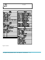
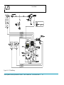
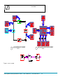
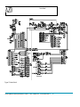
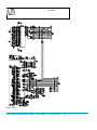
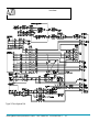
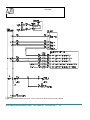
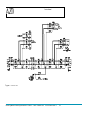
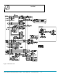
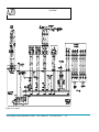
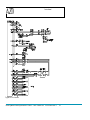
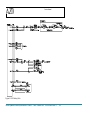
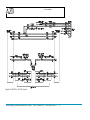
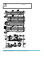
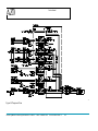
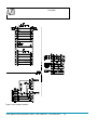
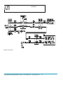
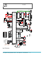
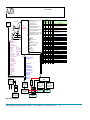
Service Manual
10 Electrical Systems and Wiring Diagrams.
Figure 28 Fuse Pane
Azure Dynamics Series Hybrid Electric Vehicle – 2006/7 Shuttle Bus
MAN500666 Rev A
113
Service Manual
Figure 29 Fuse Label
Azure Dynamics Series Hybrid Electric Vehicle – 2006/7 Shuttle Bus
MAN500666 Rev A
114
Service Manual
Figure 30 12 V Dual Battery
Azure Dynamics Series Hybrid Electric Vehicle – 2006/7 Shuttle Bus
MAN500666 Rev A
115
Service Manual
1
A/C SYSTEM BLOCK DIAGRAM
Scale: NTS
2
ESC CLUTCH CONTROLLED DIAGRAM
Scale: NTS
Figure 31 Cab AC System
Azure Dynamics Series Hybrid Electric Vehicle – 2006/7 Shuttle Bus
MAN500666 Rev A
116
Service Manual
Figure 32 Inertia Switch
Azure Dynamics Series Hybrid Electric Vehicle – 2006/7 Shuttle Bus
MAN500666 Rev A
117
Service Manual
Figure 33 PCM
Azure Dynamics Series Hybrid Electric Vehicle – 2006/7 Shuttle Bus
MAN500666 Rev A
118
Service Manual
Figure 34 Driver Input and Fuel
Azure Dynamics Series Hybrid Electric Vehicle – 2006/7 Shuttle Bus
MAN500666 Rev A
119
Service Manual
Figure 35 Gear Selector See REF500334-PB -- ELEC LOOP, GEAR SELECTOR, MY06 W42 GAS SB.
Azure Dynamics Series Hybrid Electric Vehicle – 2006/7 Shuttle Bus
MAN500666 Rev A
120
Service Manual
Figure 36 Powertrain CAN
Azure Dynamics Series Hybrid Electric Vehicle – 2006/7 Shuttle Bus
MAN500666 Rev A
121
Service Manual
Figure 37 DUO CAN
Azure Dynamics Series Hybrid Electric Vehicle – 2006/7 Shuttle Bus
MAN500666 Rev A
122
Service Manual
Figure 38 Instrument Cluster
Azure Dynamics Series Hybrid Electric Vehicle – 2006/7 Shuttle Bus
MAN500666 Rev A
123
Service Manual
Figure 39 HV System
Azure Dynamics Series Hybrid Electric Vehicle – 2006/7 Shuttle Bus
MAN500666 Rev A
124
Service Manual
Figure 40 DUO Inverter
Azure Dynamics Series Hybrid Electric Vehicle – 2006/7 Shuttle Bus
MAN500666 Rev A
125
Service Manual
Figure 41 HV Battery Pack
Azure Dynamics Series Hybrid Electric Vehicle – 2006/7 Shuttle Bus
MAN500666 Rev A
126
Service Manual
Figure 42 300VDC to 12 VDC Inverter
Azure Dynamics Series Hybrid Electric Vehicle – 2006/7 Shuttle Bus
MAN500666 Rev A
127
TEMP1
TEMP2
Service Manual
Figure 43 Power Assist System
Azure Dynamics Series Hybrid Electric Vehicle – 2006/7 Shuttle Bus
MAN500666 Rev A
128
Service Manual
Figure 44 Pumps and Fans
Azure Dynamics Series Hybrid Electric Vehicle – 2006/7 Shuttle Bus
MAN500666 Rev A
129
Service Manual
Figure 45 Misc Workhorse Harnesses
Azure Dynamics Series Hybrid Electric Vehicle – 2006/7 Shuttle Bus
MAN500666 Rev A
130
Service Manual
Figure 46 ABS System
Azure Dynamics Series Hybrid Electric Vehicle – 2006/7 Shuttle Bus
MAN500666 Rev A
131
Service Manual
Powertrain
CAN – DB9
Powertrain - CAN bus: 500k bps
IGN KEY
CAN2-23+/37Key Start (12VHi Effect)
Vcsw
Vign
KeyOn-16
Crash Switch
Vbat
PS-HSOUT-14
PS-HSOUT-28
PS-HSOUT-42
PS-MC-30
Fuse
Fuse
Fuse
Fusible
Link
-
EV Switch – dash mounted
NO
12V
+
Battery
Engine Coolant
Temperature Sensor
12V
2kΩ
ADIN8-27
10VREF
Accelerator Pedal POT1
Accelerator Pedal POT2
A
Chassis
PWR-8
PWM 1 RTN-3
Throttle 1
Throttle 2
(Siemens)
Flash: 512 kbytes
RAM: 256 kbytes
EEPROM: 8kbytes
REF-4
J2-G
PPS1
AN-1
PWM to Analog
Converter (PAC) RET-12
J2-F
PPS1-RET
Throttle
Actuator Control
Module (TAC)
PPS2-5V REF
REF-5
PWM 2-11
RET-11
GND-7
J2-B
PPS2
AN-2
A
ABS Active
ABS
Module
Sensor Ground
ABS
Pump
Vign
NC
Brake Switch
J2-C
ADIN4-25
+10Vext-32
ADIN2-24
ADIN7-41
J1-14
Engine J2-46
Controller
Engine Oil Pressure
J1-63
J2-58
Vcsw
Cab
Heating
Pump
ICE Enb, DOL
Engine On
Vbat
Transmission
Range Sensor
(GM)
NO
A
B
P
P
0
1
0
C
R
0
0
1
P
N
1
0
0
D
1
0
1
J1-19
33Ω
12Ω Vign
J2-47
DUO Inverter
Mot & Gen
J2-53
Vign
ADIN3-39
DO20-10
Emergency STOP
(mandatory for Shuttle Bus only)
Safety Cut off (DOH)
ABS Rear Wheel Speed
(P42 chassis only)
T. Resistor:120Ω
DO19-11
Power Assist
Switch
HV+
L41
HV-
M2
KeyOn-19
T
TEMP_RTN - 27
o
Temperature
from Inductor
CAN-16+/26-
DUO-CAN
Vign DB9
9
CAN 7+/2-
820Ω
10VREF
Diode only
mandatory when
buzzer present
GND-9
Vbat
ABS
Module
Vign
NC Low Pressure
Enb-25
NC
PWM22-8
ADIN5-40
Park Brake
TEMP_EXT - 15
DUO-CAN bus
Brake Failure
J2-3
Batt-8
220Ω
J2-51
J1-17
Wake
Vbat
33Ω
AGND-15
T. Resistor:120Ω
3
12V Starter, DOH, 2.5A
1kΩ
Vcsw Vbat
Vcsw Vbat
Pin-5
12V
Starter
6
8
Sw P
4
Sw B
5
Sw A
B
A
DIN12-21
Instrumentation
Ground
DO25-2 Rad. Cooling Fan, DOL
ADIN1-38
Low
Temp
Fan 1
DIN14-22
PWM21-9
X01-1
X01-4
Power Assist
Low Pressure
Warning Buzzer
(Mandatory for
Shuttle Bus only)
5Ω
J2-6
J2-2
Low
Temp
Fan 2
HV+
DO28-5 Power Assist Enable, DOL
Regen Disable Switch
(Shuttle Bus only)
X01-2
J1-13
Fuel Level
Sender
(240Ω)
J2-48
Trans “Mode B”, DOH, 2.5A
J2-5
Fuel Level
J2-54
Engine Fuel
Pump
Vign
PE
(GM)
J1-75
Vcsw
DIN11-35
DO18-12
Pin-5
T. Resistor:
120Ω
J3-2+/3Back Light Dimmer
J3-15
Vbat
J1-11
Hi Beam
Vign
J1-9
J2-12
Left Turn
Instrument J1-10
Cluster
Right Turn
(Vansco)
J1-12
Seat Belt
J1-1
Headlights On
J1-5
ABS Warning
J2-19
D1 D2 D3
Check Engine
J1-07
CAN1-31+/17-
Fuel Level
HV-
Z
e
A
Brake Switch
HV+
J2-D
PPS2-RET
J2-8
(Purolator only; disconnect
on Shuttle Bus)
Neutral
Vcsw
(Cobasys)
PWM 2 RTN-2
DO27-4
240VAC/16A
A+/Ba
NiMH
N
Battery Pack
U 336V 8.5Ah
L
Gen II
Vbat
J2-J
(Axiomatic)
PWM 1-10
CPU: C167, 16bit, 20MHz
12V
(GM)
Powertrain
Control
Module PWM24-6
DICO PWM23-7
DIN10-20
10VREF
°C
Alternator
ADIN6-26
T. Resistor:
120Ω
PPS1-5V REF
Pin-9 Vign
Pin-7+/2-
Pin-3
Vign
Ch-On
X02-1
MES-DEA
Charger X02-8
X02-3/5
HV-
HV+
Note: This is an external
battery charger not normally
connected to vehicle.
PWM
note
CH-Plug
Charger On, Hi (12V) Effect
PWM(305Hz)
Conn-On-Dmy
1k
Vign
NO
Vbat
LGND-29
Casing
GND
(Thermo King)
Air Con P1-01
Control Panel
ClimaAIRE 2
Vign
Air Con Dimmer
220kΩ
Vbat
Air Con
Clutch Relay
GND-1
(Thermo King)
P2-09
P2-09
P1-10 P1-18
Vign
HV+
J6-1
J6-13
Vbat
HV-
Chassis Ground
A
DICO Sensor Ground
PA Motor
Inverter
(Satcon)
HV+ HV-
2.2kΩ
DCDC Converter Enable,DOH
DIN9-34
2
10VREF
DO26-3
GND
Charger
Connector
Note: During normal
operation, only CH_Plug
is connected to ground
DO17-13
DIN13-36
1
1
3
2
DCDC
Converter
1
3
2
DCDC
Converter
(Satcon)
12V
Chassis
LT Pump 2
LT Pump 1
HV-
Air Con Motor
Inverter
DMOC 245
HV+ HV-
(Satcon)
12V
Chassis
(Shuttle Bus only)
(Azure)
(Shuttle Bus only)
Figure 47 Vehicle Interface
Azure Dynamics Series Hybrid Electric Vehicle – 2006/7 Shuttle Bus
MAN500666 Rev A
132
Service Manual
ABS Rear Wheel Speed, Active Low PWM
Safety Cut Off , Active High
ICE Enable, Active Low
E-Drive, Active Low
DICO
Powertrain
Control Module
(PCM
PRND
Accel
3
2
BRK
ABS Active
Oil Pressure
Charger On, 12V effect
Fuel Level
Brake Switch (NC, Active High)
Conn-On-Dmy (Active Low)
Engine Coolant Temp
Key-Start
Crash Switch
Regen Disable
Gauges
– Vehicle Speed (km/h)
– Battery SOC (%)
– Fuel Level (%)
– Powertrain Temperature (C)
Powertrain CAN—500Kbps
Throttle B
Throttle A
PWM to
Analog
Converter
TAC
-- Key Start Acknowledge
-- Precharge active
-- Precharge state
-- BMS mode
-- Isolation Resistance
-- Total Batt Voltage
-- Total Batt Current
-- Max discharge-current
-- Min regen-current
-- Max Batt volt
-- Min Batt volt
-- SOC
-- BMS status
-- BMS Fault
Battery Control
Module (BCM)
Junction Box
1.0mF
ECU
Gasoline Engine
( GM 4.8L max.
161kw @ 4000rpm )
Battery Pack
(336V x 8.5Ah NiMH,
Liquid Cooling)
336V
DUO CAN
Warning Lights
LCD Text
1 – Charging
Line 1 – 8x ASCII
2 – Wait
Line 2 – 8x ASCII
3 – Check Engine
Low Side Outputs
4 – Cruise
1 – Output 1
5 – Economy Mode
2 – Output 2
6 – DRL On Warning
3 – Output 3
7 – Water in Fuel
8 – Engine brake Warning
9 – Stop Warning
10 – RBS Disabled
11 – Generic Indicator
12 – High Voltage Hazard
13 – 12V Charge System
14 – Seat Belt
15 – Brake Warning
16 – ABS
17 – Service Required
18 – Oil Pressure
19 – Low Fuel Level
20 – Drive Enabled
21 – E Drive
22 – Power Limit
Rad Cooling Fan, Active Low
DC-DC and LT pump Enable, Active High
12V Starter Enable, Active High
Charger Control, Active Low PWM (305Hz)
Power Assist Enable, Active Low
Engine Throttle Position A, Active Low PWM
Engine Throttle Position B, Active Low PWM
Transmission DTC Fix, Active High
1.1mH/
240A max
Instrument
Cluster (IC)
#
1
CAN ID
(hex)
21A
2
3
250
252
4
253
5
6
7
8
9
10
11
12
13
14
15
16
17
18
19
20
21
22
23
24
25
26
27
28
254
255
256
257
258
259
25E
25F
700
701
702
703
7B0
7B1
7B2
7B3
7B4
7B5
7B6
7B7
7B8
7B9
7BA
7BB
Update
Rate
(ms)
Type From
To
Data
50
cmd PCM BCM Pack connect command, clear faults
Pack state, precharge state, isolation resistance,
100
data BCM PCM fault codes, SOC, coolant temp
100
data BCM PCM Pack voltage, current
Max and min module voltage, w/ corresponding
200
data BCM PCM temperature and number
Max and min module temperature, w/
200
data BCM PCM corresponding voltage and number
1000
data BCM PCM Pack trip amp-hours in, out
100
data BCM PCM Pack max power limits, discharge and charge
100
data BCM PCM Pack lifetime amp-hours in
100
data BCM PCM Pack lifetime amp-hours out
100
data BCM PCM Pack percent of life remaining
1000
data BCM PCM Pack stored faults
one-shot data BCM PCM Pack software version
50
cmd PCM
IC IC vehicle speed, SOC, fuel level, temperature
50
cmd PCM
IC IC indicator lamps and outputs
100
cmd PCM
IC IC text line 1
100
cmd PCM
IC IC text line 2
100
data PCM (diag) accelerator and brake inputs
100
data PCM (diag) generator and engine speed feedback
100
data PCM (diag) HV power variables
100
data PCM (diag) generator power
100
data PCM (diag) motor torque, battery power
100
data PCM (diag) motor, generator, inverter temperature
100
data PCM (diag) bit flags
100
data PCM (diag) modes/control bits
100
data PCM (diag) vehicle control feedback its
100
data PCM (diag) vehicle control feedback bits
100
data PCM (diag) accelerator and engine variables
100
data PCM (diag) bit flags
Siemens DUO Inverter
(650V)
Generator: Siemens
90kW(max. cont) &
110kW(max. peak)@
4000rpm
Power steering
Controller
Motor:Siemens
80kw(max. cont),
110kw(max. peak)@
9000rpm
Power steering
motor
300V DC – 12V DC
Converter
Figure 48 Block Diagram
Azure Dynamics Series Hybrid Electric Vehicle – 2006/7 Shuttle Bus
MAN500666 Rev A
133