1
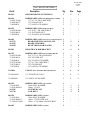
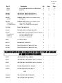
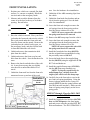
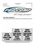
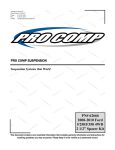
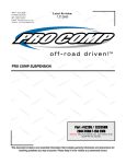
2360 Boswell Road
Chula Vista, CA 91914
Phone
619.216.1444
Fax
619.216.1474
E-Mail
[email protected]
Latest Revision:
12.4.12
PRO COMP SUSPENSION
Suspension Systems that Work!
Part #
55717/55717MX
2007-2013 Jeep
Wrangler 4WD 2
Door & 4 Door JK
Stage 1
4” Lift Kit
This document contains very important information that includes warranty information and instructions for
resolving problems you may encounter. Please keep it in the vehicle as a permanent record.
55717/55717MX
Created
12.4.12
Box 1-PN 55717/55717MX-1
Part #
Description
Qty
Illus.
Page
90-4149
REAR BUMPSTOP EXTENSIONS
2
5
9
90-6536
70-0501751800
72-050100812
73-05000830
HARDWARE PACK: Rear Bump Stop Lock Plate
1/2” X 1 3/4” GR. 8 HEX BOLT
1/2” NYLOCK NUT
1/2” SAE FLAT WASHER
1
2
2
2
5
5
5
9
9
9
90-6525
70-0251001800
72-025100816
73-02500830
HARDWARE PACK: Brake Line Drop
1/4”-20 X 1” GR. 8 HEX BOLT
1/4”-20 STOVER NUT
1/4”-20 SAE FLAT WASHER
1
4
4
8
-
-
90-6605
90-3719
90-1539
90-2650
HARDWARE PACK: Brake Line/Track Bar/Bump Stop
REAR BUMPSTOP LOCK PLATE
BRAKE LINE DROP
REAR TRACK BAR SPACER
1
2
4
1
5
4
9
8
90-5841
REAR TRACK BAR BRACKET
1
4
8
90-6722
70-0563251800
72-056100816
73-05600830
70-0371001800
72-037100816
73-03700830
HARDWARE PACK: Rear Track Bar Bracket
9/16” X 3 1/4” GR. 8 HEX BOLT
9/16” STOVER NUT
9/16” SAE FLAT WASHER
3/8” X 1” GR. 8 HEX BOLT
3/8” STOVER NUT
3/8” SAE FLAT WASHER
1
1
1
2
2
2
4
4
4
4
4
4
4
8
8
8
8
8
8
13-90496
U-BOLT: Rear Track Bar Relocation Bracket
1
4
8
72-050100816
1/2” STOVER NUT GR. C
2
4
8
73-05000830
1/2" SAE FLAT WASHER
2
4
8
90-6529
73-01410940
72-01415008812
90-3245
90-3718
HARDWARE PACK: Jeep Cam Kit
14mm FLAT WASHER
14mm– 1.5 NUT
NOTCHED CAM
CAM BOLT
1
1
1
1
1
-
-
4
4
4
4
8
8
8
8
90-6526
73-01210940
72-01215008812
71-120601751000
HARDWARE PACK: Sway Bar
12mm FLAT WASHER
12mm– 1.75 STOVER NUT
12mm– 1.75 X 60mm 10.9 HEX BOLT
1
-
-
8
4
4
-
-
90-6042
HARDWARE PACK: Sway Bar
2
-
-
2
55717/55717MX
Created
12.4.12
Part #
45359
60859
Description
Qty
Illus.
Page
4
4
2
2
6
6
5/8” RUBBER HOURGLASS BUSHING
SLEEVE
90-8012
90-2008
JEEP SWAY BAR END LINK: Rear
JEEP SWAY BAR END LINK: Front
2
2
2
6
90-6537
90-2207
HARDWARE PACK: Front X-Member Spacer
1/2” Spacer
1
2
-
-
90-6538
73-01210930
71-120501051000
HARDWARE PACK: Front X-Member Spacer
12mm FLAT WASHER
12mm– 1.5 X 50mm 10.9 HEX BOLT
1
-
-
2
2
-
-
15-11309
FRONT BUMPSTOP
2
-
-
94-5987
REAR BRAKE LINE DROP BRACKET
1
3
7
90-6525
25C100HCS8Y
25CNUCZ
25NWSAZ
HARDWARE PACK: Front/Rear Brake Line Bracket
1/4”-20 X 1 HEX BOLT GR. 8
1/4”-20 STOVER NUT GR. C
1/4” SAE FLAT WASHER
1
4
4
8
3
3
3
7
7
7
10999
11" ZIP TIE: Black
4
-
-
90-4337
BRAKE LINE SLEEVING
2
-
-
90-7203
FRONT BRAKE LINE BRACKET: Drvr
1
1
5
90-7204
FRONT BRAKE LINE BRACKET: Pass
1
1
5
FOLLOWING PARTS ARE USED IN CONJUNCTION WITH THIS KIT. THEY ARE PACKAGED
AND MUST BE ORDERED SEPARATELY.
55397
JEEP FRONT COIL SPRING
1
-
-
55217
JEEP REAR COIL SPRING (2 Door Vehicles)
1
-
-
55207
JEEP REAR COIL SPRING (4 Door Vehicles)
1
-
-
926511
ES9000 SERIES FRONT SHOCK
2
-
-
926501
ES9000 SERIES REAR SHOCK
2
-
-
2
-
-
2
-
-
OR
MX6013
MX-6 SERIES FRONT SHOCK
MX6151
MX-6 SERIES REAR SHOCK
3
♦
55717/55717MX
Created
12.4.12
Introduction:
This installation requires a professional mechanic!
♦
We recommend that you have access to a factory service manual for your vehicle to assist in the disassembly and reassembly of your vehicle. It contains a wealth of detailed information.
♦
Prior to installation, carefully inspect the vehicle’s steering and driveline systems paying close attention to
the tie rod ends, ball joints, wheel bearing preload, pitman and idler arm. Additionally, check steering-toframe and suspension-to-frame attaching points for stress cracks. The overall vehicle must be in excellent
working condition. Repair or replace all worn or damaged parts!
♦
Read the instructions carefully and study the illustrations before attempting installation! You may save yourself a lot of extra work.
♦
Check the parts and hardware against the parts list to assure that your kit is complete. Separating parts according to the areas where they will be used and placing the hardware with the brackets before you begin
will save installation time.
♦
Check the special equipment list and ensure the availability of these tools.
♦
Secure and properly block vehicle prior to beginning installation.
♦
ALWAYS wear safety glasses when using power tools or working under the vehicle!
♦
Use caution when cutting is required under the vehicle. The factory undercoating is flammable. Take appropriate precautions. Have a fire extinguisher close at hand.
♦
Foot pound torque readings are listed on the Torque Specifications chart at the end of the instructions.
These are to be used unless specifically directed otherwise. Apply thread lock retaining compound where
specified.
♦
Please note that while every effort is made to ensure that the installation of your Pro Comp
lift kit is a positive experience, variations in construction and assembly in the vehicle
manufacturing process will virtually ensure that some parts may seem difficult to install.
Additionally, the current trend in manufacturing of vehicles results in a frame that is highly
flexible and may shift slightly on disassembly prior to installation. The use of pry bars and
tapered punches for alignment is considered normal and usually does not indicate a faulty
product. However, if you are uncertain about some aspect of the installation process,
please feel free to call our tech support department at the number listed on the cover page.
We do not recommend that you modify the Pro Comp parts in any way as this will void any
warranty expressed or implied by the Pro Comp Suspension company.
PLEASE NOTE:
Due to differences in manufacturing, dimensions and inflated measurements, tire
and wheel combinations should be test fit prior to installation. Tire and wheel choice is crucial in
assuring proper fit, performance, and the safety of your Pro Comp equipped vehicle. For this application, we recommend a 17” wheel not to exceed 10” in width with a maximum backspacing of
5” must be used. Additionally, quality tire of radial design, not exceeding 35” tall X 12.5” wide is
also recommended. Please note that the use of a 35” X 12.5” tire may require fender modification. Violation of these recommendations will not be endorsed as acceptable by Pro Comp Suspension and will void any and all warranties either written or implied.
Optional Equipment Available from your Pro
Comp
TRACK BAR: JTB 402
JK LIGHT BAR: 23700
FRONT ARM CAMS: 20-65227
REAR ARM CAMS: 20-65228
Also, check out our outstanding selection of Pro Comp tires to
compliment your4new installation!
Distributor!
55717/55717MX
Created
12.4.12
FRONT INSTALLATION:
area. Save the hardware for reinstallation.
1. Position your vehicle on a smooth, flat, hard
surface (i.e. concrete or asphalt). Block the
rear tires and set the emergency brake.
8. Unbolt the all the ABS mounting clips from
the vehicle.
2. Measure and record the distance from the
center of each wheel to the top of its fender
opening. Record below.
9. Unbolt the front brake line brackets and unclip it from the spring pad. Save the hardware for reinstallation.
LF:
RF:
LR:
RR:
10. Lower the front axle enough to remove the
coil springs from the front spring pockets.
Save the factory isolators for re-use.
NOTE: Be sure to support the axle while
the springs and shocks are removed.
3. Place the vehicle in neutral. Place your floor
jack under the front axle and raise the vehicle.
Place jack stands under the frame rails and
lower the frame onto the stands. Remove the
jack and place the vehicle back in gear, set
the emergency brake, and place blocks both
in front and behind the rear wheels.
11. Remove the OE bump stops from the vehicle.
12. Lower the front axle enough to remove the
coil springs from the front spring pockets.
Save the factory isolators for re-use.
NOTE: Be sure to support the axle while
the springs and shocks are removed.
4. Unbolt and remove the transmission skid
plate from the vehicle.
13. Install the front brake line drop (90-1539)
into the original frame mounting hole using
the previously removed OE bolt.
5. Unbolt and remove the front sway bar end
links from the vehicle. Save the hardware for
reuse.
14. Secure the brake line to the supplied drop
bracket (90-1539) using the supplied 1/4”-20
X 1” bolt and hardware.
6. Remove the shocks on both sides of the vehicle. It may be necessary that you slightly
raise the axle to unload the shocks for removal.
15. Install the supplied bump stops (15-11309)
into the OE bump stop mounting cup.
NOTE: To properly seat the newly installed bump stops, carefully lower the
weight of the vehicle onto the bump stops.
7. Unbolt the front track bar from the front axle
mount and secure up and out of the work
16. Carefully lower the front axle to ease in the
new front coil spring installation. Using the
factory isolators install the Pro Comp coil
springs (55397-2) into the spring buckets and
raise the front axle into place. Make sure the
front coil spring seats properly on the lower
spring perch.
Illustration 1
Front Brake Line
Bracket
OE Bolt
Front Spring
Pad
STEPS 17 through 19 are for 2011- 2013
models ONLY!
1/4” X 1” Bolt
17. Install the front brake line brackets (90-7203
drvr and 90-7204 pass) to the front spring
pads and secure using the provided 1/4” X 1”
bolts and hardware. See ILLUSTRATION 1.
Brake Line Bracket 90-7203 drvr
and 90-7204 pass
5
55717/55717MX
Created
12.4.12
Illustration 2
24. Install your new Pro Comp front shocks
(MX6013 or ES9013 w/shaft end up) using
the OE hardware. Torque the upper mounting hardware to 17 ft./lbs. and the lower to 35
ft./lbs.
Front Sway Bar End
Link Assembly
(FRONT)
SWAY BAR
LINK
90-2008
BUSHING
45359
25. On both sides of the vehicle, check the
routing of the brake lines and the ABS wire
harnesses. There must be no pinching,
rubbing, or stretching of either component.
Use zip ties to secure these items to the
steering components. At full droop, cycle the
steering from lock to lock while observing the
reaction of these components. Reposition
them if needed.
SLEEVE
60859
18. Secure the OE brake line brackets to the Pro
Comp brackets using the previously removed
OE hardware. See ILLUSTRATION 1.
26. Reinstall the front wheels and lower the vehicle to the ground. Torque the lug nuts according to the wheel manufacturers recommendations.
19. Remove the retaining clips that retain the
ABS wire to the OE brackets. Wrap the OE
ABS lines with the provided protective
sleeves (90-4337) and secure with the supplied zip ties (10999).
27. Reinstall the OE front track bar to the axle
mount using the previously removed OE
hardware. Torque the track bar mounting
bolt according to manufacturers specifications.
20. Assemble the front sway bar end links (902041) using the supplied bushings (45359)
and sleeves (60859) from hardware pack (906042). See ILLUSTRATION 2.
⇒
21. Install the front sway bar end link (90-2008)
into original mounting bracket on the axle
using the OE hardware.
On completion of the installation, have
the suspension and headlights realigned.
⇒
After 100 miles recheck for proper
torque on all newly installed hardware.
⇒
Recheck all hardware for tightness after off road use.
NOTES:
22. Bolt the remaining end of the sway bar end
link to the front sway bar using the supplied
12mm X 60mm bolt and hardware. Torque
the 12mm hardware according to the torque
chart on page 10.
23. Reinstall the transmission skid plate using the
supplied (2) 1/2” spacers (90-2207) and
12mm-1.5 X 50mm bolts in the frame rail
mounting bolts only. Secure the remaining
rear hole to the frame using the previously
removed OE bolt. Torque the crossmember
hardware according to the torque chart on
page 10.
6
55717/55717MX
Created
12.4.12
REAR INSTALLATION:
1. Block the front tires and raise the rear of the
vehicle. Support the frame with jack stands
forward of the rear springs.
14. Insert the (2) 3/8” X 1” bolt into the track bar
bracket and secure it to the driver side rear axle
shock mount. See ILLUSTRATION 4.
2. Remove the rear wheels.
15. Tighten the previously installed 9/16” and 3/8”
hardware.
3. Unbolt the rear track bar from the rear axle
mount and secure up and out of the work
area. Save the hardware for reinstallation.
16. Install the U-bolt around the rear end axle tube
and secure to the rear track bar relocation
bracket (90-5841) using the supplied 1/2”
washer and nut. See ILLUSTRATION 4.
4. Remove the shocks on both sides of the vehicle. It may be necessary that you slightly
raise the axle to unload the shocks for removal.
17. Torque the 3/8”, 1/2” U-bolt and 9/16” track
bar hardware according to the torque chart on
page 10.
5. Unbolt and remove the rear sway bar end
links from the vehicle. Save the hardware for
reuse.
6. Lower the rear axle enough to remove the
coil springs from the rear spring pockets.
Save the factory isolators for re-use.
NOTE: Be sure to support the axle while
the springs and shocks are removed.
18. Carefully lower the rear axle to ease in the
new rear coil spring installation. Using the
factory isolators install the Pro Comp rear
coil springs (55217-2 two door or 55207-2
four door) into the spring buckets and raise
the rear axle into place. Make sure the coil
spring seats properly on the lower spring
perch.
7. Using a twisting motion remove the rear
bump stops from the factory mounts.
NOTE: Be sure to reinstall the factory
isolators before raising the springs into place.
8. Unbolt the rear brake line hangers from the underside of the floor board. Save the hardware
for reinstallation.
19. Slide the 1/2” X 1 3/4” Bolt through the center of the bump stop lock plate (90-3719).
Install the lock plate assembly to the original
bump stop frame mounting bracket. Secure
using a 1/4 turn clockwise. See ILLUSTRA-
9. Unbolt the rear brake line brackets from the
vehicle. Save the hardware for reinstallation.
10. Install the rear brake line drop bracket (945987) onto the OE studs and secure using the
previously removed hardware. See ILLUSTRATION 3.
Illustration 3
94-5987 Brake
Line Drop
Bracket
11. Secure the OE brake line hangers to the previously installed brake line drop bracket (945987) using the supplied 1/4” X 1” bolts and
hardware. See ILLUSTRATION 3.
Rear Brake Line Drop
Bracket
Vehicle Floor
Board
OE
Hardware
1/4” X 1”
Bolts
12. Install the rear brake line drop (90-1539) into
the original frame mounting hole using the
previously removed OE bolt.
13. Install the driver side rear track bar relocation
bracket (90-5841) into the original track bar
mounting pocket using the supplied 9/16” X 3
1/4” bolt and supplied spacer (90-2650). See
ILLUSTRATION 4.
OE Brake Line
Hangers
7
55717/55717MX
Created
12.4.12
Illustration 4
Rear Track Bar
Relocation Bracket
Rear
Track
Bar
Cam
Hardware
13-90496
U-Bolt
Rear Axle
90-5841 Rear Track
Bar Relocation Bracket
90-3718
Cam Bolt
OE Track
Bar Mount
Pocket
3/8” X
1” Bolts
Rear Track
Bar Spacer
90-2650
9/16” X 3
1/4” Bolt
1/2” U-Bolt Hardware
TION 5.
(MX6151 or ES9151 w/shaft end up) using
the OE hardware. Torque the upper mounting hardware to 20 ft./lbs. and the lower to 35
ft./lbs.
20. Slide the rear bump stop extensions over the
mounted lock plate assembly and secure using the supplied 1/2” hardware from pack
(90-6536). Torque hardware to 35 ft./lbs.
See ILLUSTRATION 5.
26. On both sides of the vehicle, check the routing
of the brake lines and the ABS wire harnesses.
There must be no pinching, rubbing, or
stretching of either component. Use zip ties to
secure these items to the steering components.
At full droop, cycle the steering from lock to
lock while observing the reaction of these
components. Reposition them if needed.
21. Reinstall the OE bump stop to the newly installed bump stop drop brackets.
22. Assemble the rear sway bar end links (908012) using the supplied bushings (45359)
and sleeves (60859) from hardware pack (906042). See ILLUSTRATION 1.
23. Install the rear sway bar end link (90-8012)
into original mounting bracket on the axle
using the OE hardware.
27. Reinstall the rear wheels and lower the vehicle to the ground. Torque the lug nuts according to the wheel manufacturers recommendations.
24. Bolt the remaining end of the sway bar end
link to the rear sway bar using the supplied
12mm X 60mm bolt and hardware. Torque
the 12mm hardware according to the torque
chart on page 10.
28. Install the rear track bar to the relocation
bracket (90-5841) using the supplied adjustable cam bolt (90-3718) and hardware from
hardware pack (90-6529). Do not torque the
cam bolt at this time. See ILLUSTRATION 4.
25. Install your new Pro Comp rear shocks
29. Position your vehicle on a smooth, flat, hard
8
55717/55717MX
Created
12.4.12
Illustration 5
Bump Stop Frame
Mount Cup
90-3719
Bump Stop
Lock Plate
Rear Bump Stop Lock
Plate Assembly
90-4149 Rear Bump
Stop Extension
OE Bump
Stop
1/2” X 1 3/4”
Bolt
1/2”
Hardware
surface (i.e. concrete or asphalt).
30. Rotate the track bar cam bolt until the wheels
are centered under the vehicle.
31. Torque track bar cam bolt to 103 ft./lbs.
32. Drive the vehicle forward and backward a
few feet to be sure that the axle is adjusted
properly and the vehicle is tracking in a
straight line.
IMPORTANT!: If the steering wheel is
not centered properly it will trigger the anti-lock
brake and traction control warning lights.
NOTES:
⇒
On completion of the installation, have
the suspension and headlights realigned.
⇒
After 100 miles recheck for proper
torque on all newly installed hardware.
⇒
Recheck all hardware for tightness after off road use.
9
55717/55717MX
Created
12.4.12
10
55717/55717MX
Created
12.4.12
Revision Page:
5.16.11: Updated kit to fit up to 2011 vehicles. Added (94-5987) Rear Brake Line drop bracket, Hardware pack (90-6525), Zip ties (10999), Brake line sleeving (90-4337), Front Brake line bracket: (907203 Drvr and 90-7203 Pass) to the BOM box-1, text and illustration #2.
8.30.12: Moved (90-3718) cam bolt into hardware pack (90-6529).
10.1.12: Changed kit fitment to include 2013.
12.4.12: Updated front brake line bracket note to include 2011 to 2013 models.
11
Notice to Owner operator, Dealer and Installer:
Vehicles that have been enhanced for off-road performance often have unique handling characteristics due to the
higher center of gravity and larger tires. This vehicle may handle, react and stop differently than many passenger cars or
unmodified vehicles, both on and off–road. You must drive your vehicle safely! Extreme care should always be taken to
prevent vehicle rollover or loss of control, which can result in serious injury or even death. Always avoid sudden sharp turns
or abrupt maneuvers and allow more time and distance for braking! Pro Comp reminds you to fasten your seat belts at all
times and reduce speed! We will gladly answer any questions concerning the design, function, maintenance and correct use
of our products.
Please make sure your Dealer/Installer explains and delivers all warning notices, warranty forms and
instruction sheets included with Pro Comp product.
Application listings in this catalog have been carefully fit checked for each model and year denoted. However, Pro
Comp reserves the right to update as necessary, without notice, and will not be held responsible for misprints, changes or
variations made by vehicle manufacturers. Please call when in question regarding new model year, vehicles not listed by
specific body or chassis styles or vehicles not originally distributed in the USA.
Please note that certain mechanical aspects of any suspension lift product may accelerate ordinary
wear of original equipment components. Further, installation of certain Pro Comp products may void the vehicle’s
factory warranty as it pertains to certain covered parts; it is the consumer’s responsibility to check with their local dealer for
warranty coverage before installation of the lift.
Warranty and Return policy:
Pro Comp warranties its full line of products to be free from defects in workmanship and materials. Pro Comp’s obligation under this warranty is limited to repair or replacement, at Pro Comp’s option, of the defective product. Any and all
costs of removal, installation, freight or incidental or consequential damages are expressly excluded from this warranty. Pro
Comp is not responsible for damages and / or warranty of other vehicle parts related or non-related to the installation of Pro
Comp product. A consumer who makes the decision to modify his vehicle with aftermarket components of any kind will
assume all risk and responsibility for potential damages incurred as a result of their chosen modifications. Warranty coverage does not include consumer opinions regarding ride comfort, fitment and design. Warranty claims can be made directly
with Pro Comp or at any factory authorized Pro Comp dealer.
IMPORTANT! To validate the warranty on this purchase please be sure to mail in the warranty card.
Claims not covered under warranty• Parts subject to normal wear, this includes bushings, bump stops, ball joints, tie rod ends and heim joints
• Discontinued products at Pro Comp’s discretion
• Bent or dented product
• Finish after 90 days
• Leaf or coil springs used without proper bump stops
• Light bulbs
• Products with evident damage caused by abrasion or contact with other items
• Damage caused as a result of not following recommendations or requirements called out in the
installation manuals
• Products used in applications other than listed in Pro Comp’s catalog
• Components or accessories used in conjunction with other manufacturer’s systems
• Tire & Wheel Warranty as per Pro Competition Tire Company policy
• Warranty claims without “Proof of Purchase”
• Pro Comp Pro Runner coil over shocks are considered a serviceable shock with a one-year
warranty against leakage only. Rebuild service and replacement parts will be available and sold
separately by Pro Comp. Contact Pro Comp for specific service charges.
• Pro Comp accepts no responsibility for any altered product, improper installation, lack of or
improper maintenance, or improper use of our products.
E-Mail: [email protected]
Website: www.explorerprocomp.com
Fax: (619) 216-1474
Ph: (619) 216-1444
PLACE
WARRANTY REGISTRATION
NUMBER
HERE: __________________