1
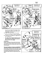
2360 Boswell Road Chula Vista, CA 91914 Phone 619.216.1444 Fax 619.216.1474 E-Mail [email protected] PRO COMP SUSPENSION Suspension Systems that Work! Part # 59002MX 2004-2006 NISSAN TITAN 4WD/2WD COIL UPGRADE KIT FOR PRO COMP KITS 59001/59004 This document contains very important information that includes warranty information and instructions for resolving problems you may encounter. Please keep it in the vehicle as a permanent record. 59002MX Created 12.5.05 Part # Description Qty. Page Illus. 59001MX-4/59004MX-4 Box 1 of 2-PN 59002MX-1 621000 COIL OVER 1 6 1a/1b/2 90-6362 90-2433 90-2494 HARDWARE PACK: Coil over mounting spacers 1 UPPER SPACERS 4 LOWER SPACERS 4 6 6 1a 1a 90-3138 COIL OVER MOUNT: UPPER BRACKET 1 6 1a/2 MX6060 MX6 SHOCKS 1 - - 90-6317 72-043200810 73-04300830 73-04300836 HARDWARE PACK: SPACER MOUNT 7/16-20 GR. 8 PLATED HEX NUT 7/16 SAE FLATWASHER ZINC 7/16 SPLIT LOCK WASHER 1 6 6 6 6 6 6 1a/1b/2 1a/1b/2 1a/1b/2 59001MX-5/59004MX-5 Box 2 of 2-PN 59002MX-2 621000 COIL OVER 1 6 1a/1b/2 90-3010 COIL OVER WRENCH LARGE 1 - - 90-3011 COIL OVER WRENCH SMALL 1 - - 90-6318 70-0502751800 73-05000830 72-050100816 HARDWARE PACK: COIL OVER MOUNT 1/2"-13 X 2 3/4" BOLT 1/2" SAE FLATWASHER ZINC 1/2-13 UNITORQUE NUT GR. C Z 1 2 4 2 6 6 6 1a 1a 1a 90-3138 COIL OVER MOUNT: UPPER BRACKET 1 6 1a/2 MX6060 MX6 SHOCKS 1 - - ATTENTION: DO NOT attempt to disassemble the shocks. The shocks and the coils are under extreme pressure and severe bodily injury may occur is disassembled. The shock heights are factory set, DO NOT adjust them until after you have completed the instructions and have driven the vehicle. If the truck still does not sit to your preference there are specific instructions in the rear of this document that outline the adjustment procedure. 2 59002MX Created 12.5.05 Introduction: ♦ ♦ ♦ ♦ ♦ ♦ ♦ ♦ ♦ ♦ ♦ This installation requires a professional mechanic! We recommend that you have access to a factory service manual for your vehicle to assist in the disassembly and reassembly of your vehicle. It contains a wealth of detailed information. Prior to installation, carefully inspect the vehicle’s steering and driveline systems paying close attention to the tie rod ends, ball joints, wheel bearing preload, pitman and idler arm. Additionally, check steering-to-frame and suspension-to-frame attaching points for stress cracks. The overall vehicle must be in excellent working condition. Repair or replace all worn or damaged parts! Read the instructions carefully and study the illustrations before attempting installation! You may save yourself a lot of extra work. Check the parts and hardware against the parts list to assure that your kit is complete. Separating parts according to the areas where they will be used and placing the hardware with the brackets before you begin will save installation time. Check the special equipment list and ensure the availability of these tools. Secure and properly block vehicle prior to beginning installation. ALWAYS wear safety glasses when using power tools or working under the vehicle! Use caution when cutting is required under the vehicle. The factory undercoating is flammable. Take appropriate precautions. Have a fire extinguisher close at hand. Foot pound torque readings are listed on the Torque Specifications chart at the end of the instructions. These are to be used unless specifically directed otherwise. Apply thread lock retaining compound where specified. Please note that while every effort is made to ensure that the installation of your Pro Comp suspension kit is a positive experience, variations in construction and assembly in the vehicle manufacturing process will virtually ensure that some parts may seem difficult to install. Additionally, the current trend in manufacturing of vehicles results in a frame that is highly flexible and may shift slightly on disassembly prior to installation. The use of pry bars and tapered punches for alignment is considered normal and usually does not indicate a faulty product. However, if you are uncertain about some aspect of the installation process, please feel free to call our tech support department at the number listed on the cover page. We do not recommend that you modify the Pro Comp parts in any way as this will void any warranty expressed or implied by the Pro Comp Suspension company. 3 59002MX Created 12.5.05 Important! Due to differences in manufacturing, dimensions and inflated measurements, tire and wheel combinations should be test fit prior to installation. Tire and wheel choice is crucial in assuring proper fit, performance, and the safety of your Pro Comp equipped vehicle. For this application, a 17” wheel not to exceed 8” in width with a minimum backspacing of 4.5” to a maximum 5”, additionally, a 17” X 9” wheel with 5” of backspacing is also acceptable. A quality tire of radial design, not exceeding 35” tall X 13.5” wide is recommended. Please note that the use of a 35” X 13.5” tire may require fender modification. Violation of these recommendations will not be endorsed as acceptable by Pro Comp Suspension and will void any and all warranties either written or implied. IMPORTANT!: Not all 17” wheels will fit over the brake calipers. Be sure to test fit the wheels prior to purchase and installation. Please Note: ∗ Front suspension and head light realignment is necessary! ∗ Speedometer and ABS recalibration will be necessary if larger tires (10% more than stock diameter) are installed. ∗ Always use NEW cotter pins on re-assembly! (These items are NOT supplied) ∗ IT IS ADVISABLE THAT YOU HAVE HELP AVAILABLE WHEN INSTALLING THIS KIT. SOME COMPONENTS ARE HEAVY AND AWKWARD. ADDITIONAL HELP IS GOOD INSURANCE AGAINST INJURY! Special Tools: Please refer to your service manual for more information. A special removal tool is required for safe removal of the tie rods. These tool may be purchased at your local Nissan dealer. You may be able to rent any of these tools at your local parts store. Equipment Available from your Pro Comp Distributor! Traction Bars: 72300B (Crew Cab) Mounting kit: 79090B Also, Check out our outstanding selection of compliment your new installation! 4 tires to 59002MX Created 12.5.05 Front Installation: 1. Prior to installing this kit, with the vehicle on the ground. Measure the height of your vehicle . This measurement can be recorded from the center of the wheel, straight up to the top of the inner fender lip. Record the measurements below. LF: RF: LR: RR: 8. Insert the mono ball spacers (90-2494) from pack (90-6362) in the bottom of the coil as seen in ILLUSTRATION 1a. NOTE: The spacers are a tight fit. A press might be needed to fit the spacers into the mono balls. 9. Install the new Pro-Comp coil over shock (621000) to the upper coil over mount (90-3138) with the supplied 1/2” X 2 3/4” hardware from pack (906318). 10. Fasten upper bracket to truck using the supplied 7/16” hardware from pack (90-6317) on the top. See ILLUSTRATION 2. NOTE: Enlarging of the factory upper coil over mount holes may be necessary. 11. Install the OE bolt through the lower shock mount and a-arm and torque to 99 ft lbs.. See ILLUSTRATION 1a. 12. Attach the tie rod end to the knuckle and torque to factory specifications. 13. Repeat the installation on the other side of the vehicle. 14. Recheck all hardware for proper installation and torque at this time. 15. Reinstall the wheels and tires and lower the vehicle to the ground. 16. Recheck the wheel lug torque on all four wheels at this time. 17.On both sides of the vehicle, check the routing of the brake lines and the ABS wire harnesses. There must be no pinching, rubbing, or stretching of either component. Use zip ties to secure these items to the steering components. At full droop, cycle the steering from lock to lock while observing the reaction of these components. Reposition them if needed. 18.On completion of the installation and 2. Ensure that your work space is of adequate size and the work surface is level. Place the vehicle in park and set parking brake. Place blocks both in front of and behind the rear wheels. Place your floor jack under the front cross member and raise vehicle. Place jack stands under the frame rails behind the front wheel wells and lower the frame onto the stands. Remove the jack and remove the front wheels. 3. Work on one side of the vehicle at a time. 4. Using the appropriate tool remove the tie rod end nut and separate from the knuckle . 5. Remove the three nuts from the top of the coil over assembly and the one large nut and bolt on the bottom. Remove the coil over from the vehicle as seen in ILLUSTRATION 1b. 6. Repeat on the other side of the vehicle. 7. Insert the mono ball spacers (90-2433) from pack (90-6362) in the top of the coil as seen in ILLUSTRATION 1a. NOTE: The spacers are a tight fit. A press might be needed to fit the spacers into the mono balls. 5 59002MX Created 12.5.05 90-6317 7/16” nut, lock and flat washer Illustration 1a 90-3138 Coil Over Mount 90-2494 LOWER SPACERS With coil spacer 90-2488 or 90-2525 Coil Spacer 90-2433 UPPER SPACERS FACTORY COIL OVER PRO-COMP COIL OVER 621000 OE BOLT OE BOLT any time you adjust the height of the coil-overs have the suspension and headlights re-aligned. 19. After 100 miles recheck for proper torque on all newly installed hardware. 20. Recheck all hardware for tightness after off road use. ∗ To adjust the height after the truck has been driven follow the instructions on the next page. Illustration 2 With coil over PN 90-6317 7/16” nut, lock and flat washer 90-3138 Coil Over Mount Enlarging of these holes may be necessary on some vehicles. ATTENTION: DO NOT attempt to disassemble the shocks. The shocks and the coils are under extreme pressure and severe bodily injury may occur is disassembled. The shock heights are factory set, DO NOT adjust them until after you have completed the instructions and have driven the vehicle. If the truck still does not sit to your preference there are specific instructions in the rear of this document that outline the adjustment procedure. Illustration 1b 90-6317 7/16” nut, lock and flat washer With coil over 1/2” X 2 3/4” Bolt 90-2433 UPPER SPACERS 6 PRO-COMP COIL OVER 621000 59002MX Created 12.5.05 Height Adjustment: 1. Prior to adjusting the shocks with the vehicle on the ground. Measure the height of your vehicle . This measurement can be recorded from the center of the wheel, straight up to the top of the inner fender lip. Record the measurements below. LF: RF: LR: RR: 2. Ensure that your work space is of adequate size and the work surface is level. Place the vehicle in park and set parking brake. Place blocks both in front of and behind the rear wheels. Place your floor jack under the front cross member and raise vehicle. Place jack stands under the frame rails behind the front wheel wells and lower the frame onto the stands. Remove the jack and remove the front wheels. 3. Work on one side of the vehicle at a time. 4. With the a-arm and shock at full droop (hanging down), clean it free from dirt and debris paying special attention to the threads. 5. Lubricate the threads with some light oil. 6. With the included wrenches, (90-3010 COIL OVER WRENCH LARGE) and (90-3011 COIL OVER WRENCH SMALL), unlock the top ring and adjust the bottom ring to your new desired height. 7. The two threaded lock rings, on the shock, should be tightened against each other before the vehicle is driven. They are both right hand thread. 8. Both sides of the truck should be set equally. 9. Repeat the adjustment on the other side of the vehicle. 10. Recheck all hardware for proper installation and torque at this time. 11. Reinstall the wheels and tires and lower the vehicle to the ground. 12. Recheck the wheel lug torque on all four wheels at this time. 13.On both sides of the vehicle, check the routing of the brake lines and the ABS wire harnesses. There must be no pinching, rubbing, or stretching of either component. Use zip ties to secure these items to the steering components. At full droop, cycle the steering from lock to lock while observing the reaction of these components. Reposition them if needed. 14.On completion of the installation and any time you adjust the height of the coil-overs have the suspension and headlights re-aligned. 15.Drive the vehicle. 16.If desired ride height is achieved wipe the excess oil from the shock and continue with the instructions. If not repeat the process until the desired lift is achieved. 17. After 100 miles recheck for proper torque on all newly installed hardware. Recheck all hardware for tightness after off road use. ATTENTION: DO NOT attempt to disassemble the shocks. The shocks and the coils are under extreme pressure and severe bodily injury may occur is disassembled. The shock heights are factory set, DO NOT adjust them until after you have completed the instructions and have driven the vehicle. If the truck still does not sit to your preference there are specific instructions in this document that outline the adjustment procedure. 7 59002MX Created 12.5.05 Rear installation 1. Block the front tires and raise the rear of the vehicle. Support the frame with jack stands forward of the rear springs. 2. Remove the shocks on both sides of the vehicle. It may be necessary that you slightly raise the axle to unload the shocks for removal. 3.Install your new Pro Comp shocks (MX6060) and torque this hardware to 75 ft. lbs. 4.Lower the vehicle to the ground. 5.Recheck the wheel lug torque on all four wheels at this time. 6.Recheck all hardware for proper installation and torque at this time. 7.On completion of the installation, have the suspension and headlights realigned. 8.After 100 miles recheck for proper torque on all newly installed hardware. 9.Recheck all hardware for tightness after off road use. 8 59002MX Created 12.5.05 9 Notice to Owner operator, Dealer and Installer: Vehicles that have been enhanced for off-road performance often have unique handling characteristics due to the higher center of gravity and larger tires. This vehicle may handle, react and stop differently than many passenger cars or unmodified vehicles, both on and off–road. You must drive your vehicle safely! Extreme care should always be taken to prevent vehicle rollover or loss of control, which can result in serious injury or even death. Always avoid sudden sharp turns or abrupt maneuvers and allow more time and distance for braking! Pro Comp reminds you to fasten your seat belts at all times and reduce speed! We will gladly answer any questions concerning the design, function, maintenance and correct use of our products. Please make sure your Dealer/Installer explains and delivers all warning notices, warranty forms and instruction sheets included with Pro Comp product. Application listings in this catalog have been carefully fit checked for each model and year denoted. However, Pro Comp reserves the right to update as necessary, without notice, and will not be held responsible for misprints, changes or variations made by vehicle manufacturers. Please call when in question regarding new model year, vehicles not listed by specific body or chassis styles or vehicles not originally distributed in the USA. Please note that certain mechanical aspects of any suspension lift product may accelerate ordinary wear of original equipment components. Further, installation of certain Pro Comp products may void the vehicle’s factory warranty as it pertains to certain covered parts; it is the consumer’s responsibility to check with their local dealer for warranty coverage before installation of the lift. Warranty and Return policy: Pro Comp warranties its full line of products to be free from defects in workmanship and materials. Pro Comp’s obligation under this warranty is limited to repair or replacement, at Pro Comp’s option, of the defective product. Any and all costs of removal, installation, freight or incidental or consequential damages are expressly excluded from this warranty. Pro Comp is not responsible for damages and / or warranty of other vehicle parts related or non-related to the installation of Pro Comp product. A consumer who makes the decision to modify his vehicle with aftermarket components of any kind will assume all risk and responsibility for potential damages incurred as a result of their chosen modifications. Warranty coverage does not include consumer opinions regarding ride comfort, fitment and design. Warranty claims can be made directly with Pro Comp or at any factory authorized Pro Comp dealer. IMPORTANT! To validate the warranty on this purchase please be sure to mail in the warranty card. Claims not covered under warranty• Parts subject to normal wear, this includes bushings, bump stops, ball joints, tie rod ends and heim joints • Discontinued products at Pro Comp’s discretion • Bent or dented product • Finish after 90 days • Leaf or coil springs used without proper bump stops • Light bulbs • Products with evident damage caused by abrasion or contact with other items • Damage caused as a result of not following recommendations or requirements called out in the installation manuals • Products used in applications other than listed in Pro Comp’s catalog • Components or accessories used in conjunction with other manufacturer’s systems • Tire & Wheel Warranty as per Pro Competition Tire Company policy • Warranty claims without “Proof of Purchase” • Pro Comp Pro Runner coil over shocks are considered a serviceable shock with a one-year warranty against leakage only. Rebuild service and replacement parts will be available and sold separately by Pro Comp. Contact Pro Comp for specific service charges. • Pro Comp accepts no responsibility for any altered product, improper installation, lack of or improper maintenance, or improper use of our products. E-Mail: [email protected] Website: www.explorerprocomp.com Fax: (619) 216-1474 Ph: (619) 216-1444 PLACE WARRANTY REGISTRATION NUMBER HERE: __________________