1
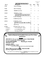
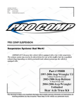
K5074B/K5075B
Revised
7.7.08
2360 Boswell Road
Chula Vista, CA 91914
Phone
619.216.1444
Fax
619.216.1474
E-Mail
[email protected]
PRO COMP SUSPENSION
Suspension Systems that Work!
K5075B
2005-2009
Toyota Tacoma
4WD/ 2WD Pre
Runner
3” Lift Kit
W/ Add-A-Leaf
K5074BB
2006-2008
Toyota FJ 4WD
3” Lift Kit
This document contains very important information that includes warranty information and instructions for
resolving problems you may encounter. Please
1 keep it in the vehicle as a permanent record.
K5074B/K5075B
Revised
7.7.08
K5074B FJ Kit Parts List:
Description
Part #
Qty.
Illus.
Page
57491
Front Coil Spring
2
1
6
57492
Rear Coil Spring
2
-
-
622053
ES6000 Front Strut
2
1
6
923553
ES9000 Rear Shock
2
-
-
OR K5075B Tacoma Parts List:
57491
Front Coil Spring
2
1
6
622053
ES6000 Front Strut
2
1
6
925518
ES9000 Rear Shock
2
-
-
567096B-5 Tacoma Add-A-leaf Box:
13129
Add-A-Leaf
2
2
10
90-3825
98-00250-1
98-00250-1
97-380
8337-1
Hardware Pack: Add-A-Leaf
2 1/2” Spring Plate– Clamps
2 1/2” Spring Plate– Straps
3/8” X 5” Center Bolt
3/8” Fine Gr. 8 Nut
1
4
4
2
2
2
2
2
2
10
10
10
10
Optional Equipment Available from your Pro Comp
Distributor!
Tacoma:
4WD/2WD Pre Runner Suspension Lift Kit: 57096/57096MX
Coil Over Upgrade Kit: 57097/57097MX*
Traction Bars: 72500B*
Mounting kit: 72083B*
Skid Plate: 57196*
Light Bar: 25000
CV Style Driveshaft: 57098*
*To be used in conjunction with Pro Comp lift kit 57096/57096MX
FJ:
4WD & 2WD Suspension Lift Kit: 57007/57007MX
Coil Over Upgrade Kit: 57008MX
Also, Check out our outstanding selection of
installation!
2
tires to compliment your new
K5074B/K5075B
Revised
7.7.08
Introduction:
♦
♦
♦
♦
♦
♦
♦
♦
♦
♦
♦
This installation requires a professional mechanic!
We recommend that you have access to a factory service manual for your vehicle to
assist in the disassembly and reassembly of your vehicle. It contains a wealth of detailed information.
Prior to installation, carefully inspect the vehicle’s steering and driveline systems
paying close attention to the tie rod ends, ball joints, wheel bearing preload, pitman
and idler arm. Additionally, check steering-to-frame and suspension-to-frame attaching points for stress cracks. The overall vehicle must be in excellent working condition. Repair or replace all worn or damaged parts!
Read the instructions carefully and study the illustrations before attempting installation! You may save yourself a lot of extra work.
Check the parts and hardware against the parts list to assure that your kit is complete.
Separating parts according to the areas where they will be used and placing the hardware with the brackets before you begin will save installation time.
Check the special equipment list and ensure the availability of these tools.
Secure and properly block vehicle prior to beginning installation.
ALWAYS wear safety glasses when using power tools or working under the vehicle!
Use caution when cutting is required under the vehicle. The factory undercoating is
flammable. Take appropriate precautions. Have a fire extinguisher close at hand.
Foot pound torque readings are listed on the Torque Specifications chart at the end of
the instructions. These are to be used unless specifically directed otherwise. Apply
thread lock retaining compound where specified.
Please note that while every effort is made to ensure that the installation of your
Pro Comp lift kit is a positive experience, variations in construction and assembly in the vehicle manufacturing process will virtually ensure that some parts
may seem difficult to install. Additionally, the current trend in manufacturing of
vehicles results in a frame that is highly flexible and may shift slightly on disassembly prior to installation. The use of pry bars and tapered punches for alignment is considered normal and usually does not indicate a faulty product. However, if you are uncertain about some aspect of the installation process, please
feel free to call our tech support department at the number listed on the cover
page. We do not recommend that you modify the Pro Comp parts in any way as
this will void any warranty expressed or implied by the Pro Comp Suspension
company.
3
K5074B/K5075B
Revised
7.7.08
Important!
Tire and wheel choice is crucial in assuring proper fit, performance, and the
safety of your Pro Comp equipped vehicle. For this application, we
recommend a 17” X 8” non hub-centric wheel with a maximum backspacing
of 4 1/2” (PN 8089-7883). Additionally, a quality tire of radial design, not
exceeding 33” tall X 12.5” wide tire (PN 27033) is recommended.
Installation of larger wheels may be possible, but must not exceed 5” of
backspacing. Be sure to check fit all wheel and tire combinations before
purchasing and installation. Violation of these recommendations will not be
endorsed as acceptable by Pro Comp Suspension and will void any and all
warranties either written or implied.
IMPORTANT!: 17” OR LARGER WHEELS MUST BE
USED IN CONJUNCTION WITH THIS LIFT KIT!
Please Note:
∗
Front suspension and head light realignment is necessary!
∗ Speedometer and ABS recalibration will be necessary if larger tires (10% more than
stock diameter) are installed.
∗ Always use NEW cotter pins on re-assembly! (These items are NOT supplied)
∗ IT IS ADVISABLE THAT YOU HAVE HELP AVAILABLE WHEN INSTALLING
THIS KIT. SOME COMPONENTS ARE HEAVY AND AWKWARD. ADDITIONAL HELP IS GOOD INSURANCE AGAINST INJURY!
NOTE: The final height of this kit is dependant upon the engine, transmission and
body configurations.
Special Tools:
Please refer to your service manual for more information.
A special removal tool is required for safe removal of the tie rods.
These tools may be purchased at your local Toyota dealer.
You may be able to rent any of these tools at your local parts store.
4
K5074B/K5075B
Revised
7.7.08
FJ & TACOMA FRONT INSTALLATION:
each side of the vehicle. Save for reinstallation.
1. Prior to installing this kit, with the vehicle
on the ground. Measure the height of your
vehicle. This measurement can be recorded from the center of the wheel,
straight up to the top of the inner fender
lip. Record the measurements below.
LF:
RF:
LR:
RR:
11. Scribe an index mark on the top of the
OE coil spring to the upper strut mounting plate.
CAUTION: The coil is under extreme pressure and severe bodily injury may
occur if the coil spring is disassembled without using a coil spring compressor.
12. Compress the coil spring on the strut assembly with a suitable coil spring compressor so that the coil spring has about
3/8” play in the strut and remove the upper strut isolator retaining nut.
2. Ensure that your work space is of adequate size and the work surface is level.
Place the vehicle in park. Place your
floor jack under the front cross member
and raise vehicle. Place jack stands under
the frame rails behind the front wheel
wells and lower the frame onto the stands.
Remove the jack and place the vehicle
back in gear, set the emergency brake,
and place blocks both in front of and behind the rear wheels.
NOTE: Do not use an impact gun to
remove the retaining nut. It will damage the
strut shaft.
13. Remove the OE coil spring isolator from
the upper strut mounting plate. See ILLUSTRATION 1.
NOTE: Inspect the front shock assemblies for any damage or fluid leakage.
Replace if necessary.
3. Remove the front wheels. Save the hardware for reinstallation.
4. Remove the front skid plate if applicable.
14. Install the new compressed coil spring
(57491) and OE isolator onto the new
strut assembly (622053) and re-attach the
upper strut mount plate using the stock
hardware. Torque the upper strut mounting plate retaining nut to 20 ft./lbs. See
ILLUSTRATION 1.
5. Disconnect the ABS lines.
6. Disconnect the sway bar end links and
remove the lower ball joint cotter pin and
nut.
7. Loosen but do not remove the lower aarm bolts to allow the lower control arm
to pivot on the bushings.
15. Decompress the coil spring on the strut
assembly. Make sure that the spring is
seated correctly into the strut assembly
and aligned with the previously scribed
index mark on the upper strut mounting
plate. See ILLUSTRATION 1.
8. Remove the (2) bolts from the lower ball
joint bracket. Save bolts for reinstallation.
9. Remove the lower strut bolt from the
lower control arm and remove the strut
assembly from the vehicle.
NOTE: the direction of the bolt for
reinstallation
16. Install the lower strut bolt in the original
position and torque to 100 ft./lbs. for the
FJ and 61 ft./lbs. for the Tacoma.
10. Remove upper strut tower nuts holding
the strut assembly to the strut tower (3) on
17. Install the strut assembly into the strut
tower and start the upper three OE nuts.
5
K5074B/K5075B
Revised
7.7.08
(Make sure that the bottom of the strut is
aligned as well). See ILLUSTRATION
1.
21. Reinstall the front skid plate if applicable.
22. Reinstall the front wheels. Reinstall the
wheels and lower the vehicle to the
ground. Torque the lug nuts according to
the wheel manufacturers recommendations.
18. Using the floor jack, raise the lower control arm and connect the lower ball joint
bracket to the knuckle using the (2) previously removed OE bolts. Apply thread
locking compound to the bolts. Torque
the bolts to 118 ft./lbs.
NOTE: Trimming of the wheel well
liner on the backside of the fender well may
be necessary depending on the tire/wheel
combination.
19. Reconnect the sway bar end links using
the previously removed OE hardware.
Torque the nut to 52 ft./lbs.
23. Lower the vehicle onto the ground and
tighten the upper strut tower OE nuts to
47 ft./lbs.
20. Reconnect the ABS lines.
Illustration 1
OE
Nuts
Strut Assembly
OE
Nuts
OE Shock
mount
Hardware
Coil Bucket
OE
Stud
Ring
622053
Strut
Strut
Assembly
57491
Coil
Spring
6
K5074B/K5075B
Revised
7.7.08
24. With the vehicle on the ground, torque the
lower A-arm cam bolts to 100 ft./lbs.
25. Recheck all hardware for proper installation and torque at this time.
IMPORTANT! BE SURE TO
BRING THE VEHICLE TO A REPUTABLE ALIGNMENT SHOP TO BE
ALIGNED!
IMPORTANT!: IF THE STEERING
WHEEL IS NOT CENTERED PROPERLY
IT WILL TRIGGER THE ANTI-LOCK
BRAKE AND TRACTION CONTROL
WARNING LIGHTS.
NOTES:
⇒ On completion of the installation,
have the suspension and headlights re-aligned.
⇒ After 100 miles recheck for proper
torque on all newly installed hardware.
⇒ Recheck all hardware for tightness
after off road use.
7
K5074B/K5075B
Revised
7.7.08
FJ REAR INSTALLATION
that everything is tight. Check for adequate clearance on all repositioned brake
lines and emergency brake cables. Make
sure you check with the suspension fully
extended, and compressed.
1. Block the front tires and raise the rear of
the vehicle. Support the frame with jack
stands forward of the rear springs.
2. Remove the rear wheels.
3. Remove the shocks on both sides of the
vehicle. It may be necessary to slightly
raise the axle to unload the shocks for removal.
13. Reinstall the wheels and lower the vehicle
to the ground. Torque the lug nuts according to the wheel manufacturers recommendations.
4. Lower the rear axle enough to remove the
coil springs from the front spring pockets.
Save the factory isolators for re-use.
14. With the vehicle on the ground reinstall
the track bar to the rear axle using the previously removed OE hardware. Torque
the OE hardware to 96 ft./lbs. See ILLUSTRATION 26.
NOTE: Be sure to support the axle
while the springs and shocks are removed.
5. Unbolt the track bar from the rear axle
mount and secure up and out of the work
area. Save the hardware for reinstallation.
NOTES:
⇒ On completion of the installation,
6. Unbolt the sway bar end links from the
sway bar. Save the hardware for reuse.
have the suspension and headlights re-aligned.
7. On both sides of the vehicle support the
rear end with a jack and unbolt the lower
control arm at the axle.
⇒ After 100 miles recheck for proper
8. Carefully lower the rear end to ease in the
new coil spring installation. Using the
factory isolators install the Pro Comp coil
springs (57492) into the spring buckets
and raise the rear axle into place. Make
sure the coil spring seats properly on the
lower spring perch.
⇒ Recheck all hardware for tightness
torque on all newly installed hardware.
after off road use.
9. Install your new Pro Comp shocks
(923553 w/shaft end up) to the OE shock
mounts. Torque the upper mounting
hardware to 18 ft./lbs. and the lower OE
mounting bolt to 72 ft./lbs.
10. Reattach the sway bar end links to the
sway bar using the previously removed
OE hardware. Torque the nut to 52 ft./
lbs.
11. Repeat the installation on the other side of
the vehicle.
12. Check all hardware at this time to ensure
8
K5074B/K5075B
Revised
7.7.08
TACOMA REAR INSTALLATION
2.
NOTE: In order to properly install
the add-a-leaf spring, it will be necessary to
contain the elasticity in the leaf spring with
“C” clamps when the center bolts are removed. Some springs have a factory helper
spring consisting of one or more flat leaves
installed at the bottom of the leaf pack. DO
NOT install the add-a-leaf spring in or below the helper spring.
9. Install the lift block (If the vehicle is
equipped with one), making sure the pins
fit properly into the holes on the spring
perch. Use your floor jack to raise the
axle to the spring. Make sure the pin on
the leaf spring fit into the holes on the
new lift block. See ILLUSTRATION 2.
NOTE: These blocks are slightly tapered and the short side of the taper is oriented to the front of the vehicle.
1. Block the front tires and raise the rear of
the vehicle. Support the frame with jack
stands forward of the rear springs.
10. Secure the assembly with the U-bolts and
high-nuts and washers. Do not torque the
U-bolts at this time. See ILLUSTRATION 2.
2. Remove the rear wheels.
3. Remove the shocks on both sides of the
vehicle. It may be necessary to slightly
raise the axle to unload the shocks for removal.
NOTE: Make sure the block sits
flush on the axle perch.
11. Repeat the installation on the other side of
the vehicle.
4. Work on one side of the vehicle at a time.
5. Support the rear axle with a floor jack and
remove the U-bolts on the driver side.
Loosen the U-bolts on the passenger side
and lower the rear axle.
12. When the installation of the remaining
side is complete, torque the U-bolts to 85
ft./lbs.
13. Install your new Pro Comp shocks
(925518 w/shaft end up) to the OE shock
mounts. Torque the upper mounting
hardware to 18 ft./lbs. and the lower OE
mounting bolt to 72 ft./lbs.
NOTE: Be sure not to over extend
the rear brake lines.
6. Use C-clamps to hold the leaves of the
rear leaf spring together and remove
spring center bolt.
14. Reinstall the wheels and tires and lower
the vehicle to the ground. Torque the
wheels to the manufacturers recommended specifications.
7. Disassemble the leaf spring and insert the
add-a-leaf (13129). See ILLUSTRATION 2.
NOTE: Add-a-leaf will be placed in
the spring assembly progressively according
to length. For example, if the existing
leaves are 32” long and 25” long and the
add-a-leaf is 28” long, place the add-a-leaf
between the existing leaves.
15. Recheck the wheel lug torque on all four
wheels at this time.
16. Recheck all hardware for proper installation and torque at this time.
17. On completion of the installation, have
the suspension and headlights re-aligned.
8. Using the C-clamps, re-clamp and bolt the
leaf pack back together using the supplied
center bolt (97-380) with the head of the
bolt facing down. See ILLUSTRATION
18. After 100 miles recheck for proper torque
on all newly installed hardware.
9
K5074B/K5075B
Revised
7.7.08
19. Recheck all hardware for tightness after
off road use.
NOTES:
⇒ On completion of the installation,
have the suspension and headlights re-aligned.
⇒ After 100 miles recheck for proper
torque on all newly installed hardware.
⇒ Recheck all hardware for tightness
after off road use.
Illustration 2
Rear Spring
U-Bolts
Leaf Spring Assembly
OE
Bump
Stop
13129 Add-A-Leaf
Center Bolt
97-380
Lift Block (If
equipped with one)
NOTE: This is just an
example. Your set up
may differ slightly from
illustration.
Axle
Hi-Nuts
10
K5074B/K5075B
Revised
7.7.08
11
K5074B/K5075B
Revised
7.7.08
Notice to Owner operator, Dealer and Installer:
Vehicles that have been enhanced for off-road performance often have unique handling characteristics due to
the higher center of gravity and larger tires. This vehicle may handle, react and stop differently than many passenger cars or unmodified vehicles, both on and off–road. You must drive your vehicle safely! Extreme care should
always be taken to prevent vehicle rollover or loss of control, which can result in serious injury or even death. Always avoid sudden sharp turns or abrupt maneuvers and allow more time and distance for braking! Pro Comp reminds you to fasten your seat belts at all times and reduce speed! We will gladly answer any questions concerning
the design, function, maintenance and correct use of our products.
Please make sure your Dealer/Installer explains and delivers all warning notices, warranty
forms and instruction sheets included with Pro Comp product.
Application listings in this catalog have been carefully fit checked for each model and year denoted. However, Pro Comp reserves the right to update as necessary, without notice, and will not be held responsible for misprints, changes or variations made by vehicle manufacturers. Please call when in question regarding new model
year, vehicles not listed by specific body or chassis styles or vehicles not originally distributed in the USA.
Please note that certain mechanical aspects of any suspension lift product may accelerate ordinary wear of original equipment components. Further, installation of certain Pro Comp products may
void the vehicle’s factory warranty as it pertains to certain covered parts; it is the consumer’s responsibility to
check with their local dealer for warranty coverage before installation of the lift.
Warranty and Return policy:
Pro Comp warranties its full line of products to be free from defects in workmanship and materials. Pro
Comp’s obligation under this warranty is limited to repair or replacement, at Pro Comp’s option, of the defective
product. Any and all costs of removal, installation, freight or incidental or consequential damages are expressly
excluded from this warranty. Pro Comp is not responsible for damages and / or warranty of other vehicle parts related or non-related to the installation of Pro Comp product. A consumer who makes the decision to modify his
vehicle with aftermarket components of any kind will assume all risk and responsibility for potential damages incurred as a result of their chosen modifications. Warranty coverage does not include consumer opinions regarding
ride comfort, fitment and design. Warranty claims can be made directly with Pro Comp or at any factory authorized Pro Comp dealer.
IMPORTANT! To validate the warranty on this purchase please be sure to mail in the warranty card.
Claims not covered under warranty• Parts subject to normal wear, this includes bushings, bump stops, ball joints, tie rod ends and heim joints
• Discontinued products at Pro Comp’s discretion
• Bent or dented product
• Finish after 90 days
• Leaf or coil springs used without proper bump stops
• Light bulbs
• Products with evident damage caused by abrasion or contact with other items
• Damage caused as a result of not following recommendations or requirements called out in the
installation manuals
• Products used in applications other than listed in Pro Comp’s catalog
• Components or accessories used in conjunction with other manufacturer’s systems
• Tire & Wheel Warranty as per Pro Competition Tire Company policy
• Warranty claims without “Proof of Purchase”
• Pro Comp Pro Runner coil over shocks are considered a serviceable shock with a one-year
warranty against leakage only. Rebuild service and replacement parts will be available and sold
separately by Pro Comp. Contact Pro Comp for specific service charges.
• Pro Comp accepts no responsibility for any altered product, improper installation, lack of or
improper maintenance, or improper use of our products.
E-Mail: [email protected]
Website: www.explorerprocomp.com
Fax: (619) 216-1474
Ph: (619) 216-1444
PLACE
12
WARRANTY REGISTRATION
NUMBER
HERE: __________________