1
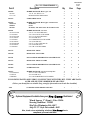
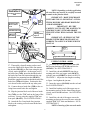
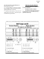
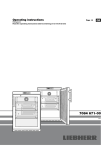
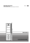
2360 Boswell Road
Chula Vista, CA 91914
Phone
619.216.1444
Fax
619.216.1474
E-Mail
[email protected]
PRO COMP SUSPENSION
Suspension Systems that Work!
IMPORTANT: Because this vehicle will be equipped with a rear 4 link suspension.
The exhaust system may need to be altered from the rear of the muffler back by a qualified
exhaust shop depending on which year/model and exhaust system type the vehicle is
equipped with.
Part # 55800
1997-2006 Jeep Wrangler TJ
w/Dana 35 and 44 rear axle
2003-2006 Jeep Rubicon
w/ Dana 44 rear axle
2004-2006 Jeep Wrangler
Unlimited
Rear Axle Truss Kit
This document contains very important information that includes warranty information and instructions for
resolving problems you may encounter. Please keep it in the vehicle as a permanent record.
55800/55800MX
Created
6.25.07
Box 1-PN 55800/55800MX-1
Part #
Description
Qty
Illus.
Page
90-6505
90-2626
15-11310
HARDWARE PACK: Rear Upper Arm
3/4" X .156” WALL X 2"
BUSHING JEEP UPPER ARM
1
2
4
2
2
6
6
90-2673
UPPER ARMS: REAR
2
2
6
90-6553
JMX-12T
SJNR12
90-2449
HARDWARE PACK: Rear Upper Arm Rod Ends
ROD END
NUTS
SPACER, .750” OD X .438” ID X 1.600” LONG
1
2
2
4
2
2
2
6
6
6
90-6551
70-0310751800
73-03100830
70-0372251800
72-037100816
73-03700030
72-043100816
70-0563001800
72-056100816
73-05600830
HARDWARE PACK: Axel Truss
5/16” X 3/4" GR 8 HEX BOLT
5/16” GR 8 SAE FLAT WASHER
3/8” X 2 1/4”GR 8 HEX BOLT
3/8” STOVER NUT
3/8” HARDENED FLAT WASHER
7/16” STOVER NUT
9/16" X 3" GR 8 HEX BOLTS
9/16" STOVER NUTS
9/16" GR 8 SAE WASHERS
1
4
4
8
8
16
1
2
2
4
1
1
1
1
1
1
1
1
1
5
5
5
5
5
5
5
5
5
90-3757
REAR AXLE TRUSS
1
1
5
90-4158
REAR AXLE VENT TUBE
1
1
5
90-3781
DANA 44 REAR DIFFERENTIAL SPACER PLATE
1
1
5
90-3767
REAR AXLE TRUSS CLAMPS
2
1
5
90-3893
DANA 35 REAR DIFFERENTIAL SPACER PLATE
1
1
5
90-3894
OVERLAP PLATE
2
1
5
90-6577
37C100HCS8Y
37CNUCZ
37NWHDY
HARDWARE PACK: Axle Truss Overlap Plate
3/8” X 1” GR. 8 HEX BOLT
3/8” STOVER NUT
3/8” SAE HARDENED FLAT WASHER
1
4
4
8
1
1
1
5
5
5
FOLLOWING PARTS ARE USED IN CONJUNCTION WITH THIS KIT. THEY ARE PACKAGED AND MUST BE ORDERED SEPARATELY.
(Unless you already have a suitable (long enough) after market rear brake line installed).
7450
STAINLESS STEEL BRAKE LINE KIT
Optional Equipment Available from your Pro
1
Comp
-
Distributor!
Winch Spacer, 1” (Front) - Pair: 55496
Steering Stabilizer: 219505
Slip Yoke Eliminator Kit: 4007
Jeep TJ CV Style Driveshaft: 4042
Also, check out our outstanding 2selection of Pro Comp tires to
compliment your new installation!
-
55800/55800MX
Created
6.25.07
Introduction:
♦
This installation requires a professional mechanic!
♦ We recommend that you have access to a factory service manual for your vehicle to assist in the
disassembly and reassembly of your vehicle. It contains a wealth of detailed information.
♦
Prior to installation, carefully inspect the vehicle’s steering and driveline systems paying close attention to the tie rod ends, ball joints, wheel bearing preload, pitman and idler arm. Additionally,
check steering-to-frame and suspension-to-frame attaching points for stress cracks. The overall
vehicle must be in excellent working condition. Repair or replace all worn or damaged parts!
♦
Read the instructions carefully and study the illustrations before attempting installation! You may
save yourself a lot of extra work.
♦
Check the parts and hardware against the parts list to assure that your kit is complete. Separating
parts according to the areas where they will be used and placing the hardware with the brackets
before you begin will save installation time.
♦
Check the special equipment list and ensure the availability of these tools.
♦
Secure and properly block vehicle prior to beginning installation.
♦
ALWAYS wear safety glasses when using power tools or working under the vehicle!
♦ Use caution when cutting is required under the vehicle. The factory undercoating is flammable.
Take appropriate precautions. Have a fire extinguisher close at hand.
♦
Foot pound torque readings are listed on the Torque Specifications chart at the end of the instructions. These are to be used unless specifically directed otherwise. Apply thread lock retaining
compound where specified.
♦
Please note that while every effort is made to ensure that the installation of your
Pro Comp lift kit is a positive experience, variations in construction and assembly
in the vehicle manufacturing process will virtually ensure that some parts may
seem difficult to install. Additionally, the current trend in manufacturing of vehicles
results in a frame that is highly flexible and may shift slightly on disassembly prior
to installation. The use of pry bars and tapered punches for alignment is considered
normal and usually does not indicate a faulty product. However, if you are uncertain
about some aspect of the installation process, please feel free to call our tech support department at the number listed on the cover page. We do not recommend that
you modify the Pro Comp parts in any way as this will void any warranty expressed
or implied by the Pro Comp Suspension company.
PLEASE NOTE:
Due to differences in manufacturing, dimensions and inflated measurements, tire
and wheel combinations should be test fit prior to installation. Tire and wheel choice is
crucial in assuring proper fit, performance, and the safety of your Pro Comp equipped
vehicle. For this application, a wheel not to exceed 8” in width with a minimum backspacing of 3.25” must be used. Additionally, a quality tire of radial design, not exceeding 33”
tall X 12.5” wide is recommended. Please note that the use of a 33” X 12.5” tire may require fender modification. Violation of these recommendations will not be endorsed as
acceptable by Pro Comp Suspension and will void any and all warranties either written
or implied.
NOTE: If you are planning to install a differential air locker you will need to use a 90 degree 3/16”
compression fitting to clear the axle truss (90-3757) and the accompanying parts and hardware.
3
55800/55800MX
Created
6.25.07
INSTALLATION INSTRUCTIONS:
5/16” X 3/4” bolts that secure the rear axle differential spacer plate to the rear axle truss. Secure the truss to the rear axle using the (2) axle
truss clamps (90-3767), 3/8” X 2 1/4” clamp
bolts and hardware. See ILLUSTRATION 1.
1. Position your vehicle on a smooth, flat, hard
surface (i.e. concrete or asphalt). Block the rear
tires and set the emergency brake.
2. Measure and record the distance from the center of each wheel to the top of its fender opening.
Record below.
LF:
RF:
LR:
RR:
12. A new vent tube hole will need to be drilled
on the front, driver side of the rear axle.
13. Use the hole in the axle truss (90-3757) ,
next to the 7/16” brake line mounting stud, on the
front side of the rear axle as a guide to drill a new
vent hole in the rear axle tube using a 3/8” drill
bit. See ILLUSTRATION 1.
NOTE: When drilling into an oil cavity,
pack the flutes of the drill bit with grease to
catch all the metal shavings.
3. Place the vehicle in neutral. Place your floor
jack under the rear axle and raise the vehicle.
Place jack stands under the front body mounts
and lower the vehicle onto the stands. Remove
the jack and place the vehicle back in gear, set
the emergency brake.
14. Once the new vent tube hole is drilled, unbolt and remove the axle truss. Clean and remove any remaining metal chips from inside and
outside the rear axle.
15. Run a bead of silicone around the new vent
tube hole in the rear axle. Also seal the original
vent tube hole in the rear axle.
NOTE: There is no pressure on the rear
axle vent system so do not overload the holes
with silicone.
DISASSEMBLY:
4. Remove the rear wheels from the vehicle.
5. Unbolt the rear sway bar from the rear axle.
Save the hardware for reuse.
6. With the rear axle fully supported, unbolt and
remove the rear upper control arms from the vehicle.
16. Install the 3/8” vent tube (90-4158) through
the hole in the rear axle truss. See ILLUSTRATION 1.
7.Remove the rear axle vent tube and unbolt the
brake line junction block from the rear axle.
17. Reinstall the axle truss (90-3757) by lining
up and reinstalling the 5/16” X 3/4” bolts that
secure the rear axle differential spacer plate (903781 for Dana 44 or 90-3893 for Dana 35) to
the rear axle truss. Reinstall the axle clamps (903767) to the rear axle. Secure the clamps using
the supplied 3/8” X 2 1/4” bolts and hardware.
See ILLUSTRATION 1.
NOTE: The vent tube should line up
with the newly drilled hole on the rear axle.
NOTE: Be sure the inside of the vent
tube is clear of silicone after installation.
8. Drain the rear axle fluid and remove the differential cover.
REAR AXLE TRUSS:
9. With the axle clear of accessories, test fit the
axle truss assembly.
10. Test fit the rear axle differential spacer plate
(90-3781 for Dana 44 or 90-3893 for Dana 35)
to the rear axle to ensure proper alignment. Secure using the OE bolts. See ILLUSTRATION
1.
18. Install the (2) overlap plates (90-3894) to the
axle truss using the (4) 3/8” X 1” bolts and hardware. Reinstall the sway bar to it’s original rear
axle mounting position. Secure the sway bar
11. Place the rear axle truss (90-3757) on top of
the differential housing. Line up and install the
4
55800/55800MX
Created
6.25.07
Illustration 1
Rear Axle Truss Install
3/8”
Hardware
Overlap
Plate
(90-3894)
and 3/8”
X 1” Bolts
90-3757
Axle
Truss
OE Rear
Sway Bar
(4) 5/16” X
3/4” Bolts
OE Sway
Bar Bolts
Rear
Axle
Pro Comp
Brake line
Junction
Block
(2) 90-3767 Axle
Truss Clamp
OE
Differential
Cover
(8) 3/8” X 2
1/4” Bolts
Rear Differential Spacer Plate 903781 Dana 44 or 90-3893 Dana 35
Overlap
Plate
(90-3894)
and 3/8”
X 1” Bolts
7/16”
Stud
90-4158
Vent Tube
OE
Differential Bolts
frame mounts to the overlap plates and rear end
using the previously removed (4) OE sway bar
bolts. See ILLUSTRATION 1.
24. Raise the differential cover into place and
secure using the OE bolts. Torque the differential spacer plate and cover hardware according to
the torque chart or manufacturers specifications.
See ILLUSTRATION 1.
19. Torque the rear axle truss (Except the (4)
5/16” bolts), overlap plate and sway bar mounting hardware according to the torque chart on
page 7 or according to manufacturers recommendations.
REAR BRAKE LINE:
NOTE: If you have a stock rear brake
line it will be necessary to purchase separately
Pro Comp Stainless Steel Brake Line kit (PN
7450)
20. Unbolt and remove the rear axle differential
spacer plate (90-3781 for Dana 44 or 90-3893
for Dana 35). See ILLUSTRATION 1.
21. Run a bead of silicone along the differential
cover mating surface.
NOTE: If you already have a suitable
(long enough) after market rear brake line installed skip this section.
22. Reinstall the differential spacer plate (903781 for Dana 44 or 90-3893 for Dana 35) to
the rear axle truss using the (4) 5/16” X 3/4”
bolts and hardware. See ILLUSTRATION 1.
25. Unbolt the rear rubber brake line from the
frame. Save the hardware for reuse.
26. Detach the rear rubber brake line from the
factory metal brake lines on the frame and the
rear axle.
23. Run another bead of silicone on the face of
the differential cover.
5
55800/55800MX
Created
6.25.07
Illustration 2
NOTE: Depending on brake application,
the steel lines may need to be carefully rerouted
to attach to the junction block.
Rear Upper Control Arm
Install
90-2673 Upper
Rear Control
Arm
SJNR12 Jam Nut
JMX12T
Rod End
IMPORTANT: MAKE SURE BRAKE
LINES ARE CLEAN AND DRY OF ANY MATERIAL BEFORE ABS BRAKE BLEEDING
AND REASSEMBLY.
IMPORTANT: BE VERY
CAREFUL NOT TO LET THE MASTER CYLINDER RUN DRY! WITH ABS BRAKES
THIS SITUATION WILL DAMAGE THE SYSTEM!
OE
Bolt
OE Nut
90-2449
Misalignment
Spacers
IMPORTANT: BLEEDING OF THE
BRAKE SYSTEM SHOULD BE DONE ACCORDING TO A JEEP FACTORY SERVICE
MANUAL.
9/16” X 3”
Bolt
Fig. 1
23 1/4”
Rear Truss
Axle Assembly
Upper Rear Control Arm 90-2673
UPPER CONTROL ARMS:
31. Assemble the rear upper control arms (902673) using bushings (15-11310) and sleeves
(90-2626). See ILLUSTRATION 2.
27. Thoroughly clean all mating surfaces and
secure the supplied 90 degree brake line mounting bracket (90-1031) to the frame using the previously removed OE bolt. At the upper end of
the brake line (7450), insert the threaded end of
the brake line from the bottom through the supplied brake line mounting bracket (90-1031).
Install the supplied jam nut to threaded end of the
brake line (7450) and tighten. Position the line
so it doesn’t make contact with any other parts.
32. Install the rod end (JMX12T) into the remaining end of the rear upper arms (90-2673)
with the jam nut (SJNR12) as shown in ILLUSTRATION 2. Adjust the arm length according
to figure 1 and tighten the jam nut.
33. Insert the spacers (90-2449) into the rod end.
See ILLUSTRATION 2.
28. Connect the new brake line (7450) to the existing frame metal brake line and tighten.
34. Install the bushing end of the upper arm to
the mounting pockets on the frame using the previously removed OE hardware. See ILLUSTRATION 2.
29. Slip the junction block end of the new brake
line (7450) over the 7/16” stud on the front of the
axle truss. Secure using the supplied 7/16” nut
from pack (90-6551). See ILLUSTRATION 1.
35. Install the rod end of the upper arm to the
mounting pockets on the rear axle truss using the
supplied 9/16” X 3” bolts and hardware. See ILLUSTRATION 2.
NOTE: Centering of the rear axle under
30. Attach the Pro Comp brake line junction
block to the existing rear axle metal brake lines
and tighten.
6
55800/55800MX
Created
6.25.07
the vehicle and pinion angle adjustment are
done using these rod ends.
CHECKS AND ADJUSTMENTS:
⇒
Recheck all hardware for tightness after the first 100 miles.
36. Torque the OE upper control arm mounting
bolts according to factory specifications and the
supplied 9/16” bolts to 130 ft./lbs.
⇒
⇒
Headlights should be adjusted.
The exhaust system may need to be altered from the rear of the muffler back by a
qualified exhaust shop.
37. Install the wheels and tires. Remove the jack
stands and lower the vehicle. Torque the lug nuts
to manufacturers specifications.
7
Notice to Owner operator, Dealer and Installer:
Vehicles that have been enhanced for off-road performance often have unique handling characteristics due to the
higher center of gravity and larger tires. This vehicle may handle, react and stop differently than many passenger cars or
unmodified vehicles, both on and off–road. You must drive your vehicle safely! Extreme care should always be taken to
prevent vehicle rollover or loss of control, which can result in serious injury or even death. Always avoid sudden sharp turns
or abrupt maneuvers and allow more time and distance for braking! Pro Comp reminds you to fasten your seat belts at all
times and reduce speed! We will gladly answer any questions concerning the design, function, maintenance and correct use
of our products.
Please make sure your Dealer/Installer explains and delivers all warning notices, warranty forms and
instruction sheets included with Pro Comp product.
Application listings in this catalog have been carefully fit checked for each model and year denoted. However, Pro
Comp reserves the right to update as necessary, without notice, and will not be held responsible for misprints, changes or
variations made by vehicle manufacturers. Please call when in question regarding new model year, vehicles not listed by
specific body or chassis styles or vehicles not originally distributed in the USA.
Please note that certain mechanical aspects of any suspension lift product may accelerate ordinary
wear of original equipment components. Further, installation of certain Pro Comp products may void the vehicle’s
factory warranty as it pertains to certain covered parts; it is the consumer’s responsibility to check with their local dealer for
warranty coverage before installation of the lift.
Warranty and Return policy:
Pro Comp warranties its full line of products to be free from defects in workmanship and materials. Pro Comp’s obligation under this warranty is limited to repair or replacement, at Pro Comp’s option, of the defective product. Any and all
costs of removal, installation, freight or incidental or consequential damages are expressly excluded from this warranty. Pro
Comp is not responsible for damages and / or warranty of other vehicle parts related or non-related to the installation of Pro
Comp product. A consumer who makes the decision to modify his vehicle with aftermarket components of any kind will
assume all risk and responsibility for potential damages incurred as a result of their chosen modifications. Warranty coverage does not include consumer opinions regarding ride comfort, fitment and design. Warranty claims can be made directly
with Pro Comp or at any factory authorized Pro Comp dealer.
IMPORTANT! To validate the warranty on this purchase please be sure to mail in the warranty card.
Claims not covered under warranty• Parts subject to normal wear, this includes bushings, bump stops, ball joints, tie rod ends and heim joints
• Discontinued products at Pro Comp’s discretion
• Bent or dented product
• Finish after 90 days
• Leaf or coil springs used without proper bump stops
• Light bulbs
• Products with evident damage caused by abrasion or contact with other items
• Damage caused as a result of not following recommendations or requirements called out in the
installation manuals
• Products used in applications other than listed in Pro Comp’s catalog
• Components or accessories used in conjunction with other manufacturer’s systems
• Tire & Wheel Warranty as per Pro Competition Tire Company policy
• Warranty claims without “Proof of Purchase”
• Pro Comp Pro Runner coil over shocks are considered a serviceable shock with a one-year
warranty against leakage only. Rebuild service and replacement parts will be available and sold
separately by Pro Comp. Contact Pro Comp for specific service charges.
• Pro Comp accepts no responsibility for any altered product, improper installation, lack of or
improper maintenance, or improper use of our products.
E-Mail: [email protected]
Website: www.explorerprocomp.com
Fax: (619) 216-1474
Ph: (619) 216-1444
PLACE
WARRANTY REGISTRATION
NUMBER
HERE: __________________