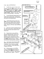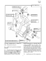
1
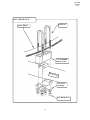
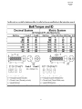
2360 Boswell Road
Chula Vista, CA 91914
Phone
619.216.1444
Fax
619.216.1474
E-Mail
[email protected]
PRO COMP SUSPENSION
Suspension Systems that Work!
Part # 57093 &
57094
Toyota T-100 4WD
IFS
4” Suspension
System
This document contains very important information that includes warranty information and instructions for
resolving problems you may encounter. Please keep it in the vehicle as a permanent record.
57093/57094
REVISED
2.1.06
Box 1 of 3-PN 57093/57094-1
Part #
90-3375
90-3377
90-3371
90-3372
90-57093-15
90-57093-16
OR
90-2102
90-2103
90-6124
15-11148
90-2109
90-6125
70-0504001500
72-05000100512
73-05000030
90-6136
90-1276
90-1278
90-1279
90-1325
90-1401
90-55089-5
90-6137
90-1301
90-2161
96-4026
90-6138
70-0311001500
70-0371501500
70-0433501500
70-0501251500
70-0501501500
70-0622501500
70-0624501500
72-03100100512
72-03700100512
72-05000100512
72-06200100512
72-04300100512
73-03100030
73-03700030
73-04300030
73-05000030
Description
Qty.
Illus.
Page
Front A-Arm Drop Brkt. - Drvr.
Front A-Arm Drop Brkt. - Pass.
Rear A-Arm Drop Brkt. - Pass.
Rear A-Arm Drop Brkt. - Drvr.
Compression Strut - Drvr. (57093)
Compression Strut - Pass. (57093)
1
1
1
1
1
1
2
2
2
2
8
8
6
6
6
6
9
9
Compression Strut - Drvr. (57094)
Compression Strut - Pass. (57094)
Hardware Pack Containing:
Bushing - Red
Sleeves, 3/4” x 1/2” x 2 3/4”
Hardware Pack Containing:
1/2” x 4” USS Gd. 5 Hex Bolt
1/2” USS Nyloc Nut
1/2” SAE Flat Washer
Bracket Bag Containing:
Rear Brake Cable Exten. Brkt.
Sway Bar Drop Brkt. - Pass.
Sway Bar Drop Brkt. - Drvr.
Center Differential Mount
Differential Drop Plate
Front Brake Drop Down Brkt.
Hardware Pack Containing:
Spacer, Locating
Spacer, 1” x 1/2” x 5/8”
Sleeve, Tapered Spindle
Hardware Pack Containing:
5/16” x 1” USS Gd. 5 Hex Bolt
3/8” x 1 1/2” USS Gd. 5 Hex Bolt
7/16” x 3 1/2” USS Gd. 5 Hex Bolt
1/2” x 1 1/4” USS Gd. 5 Hex Bolt
1/2” x 1 1/2” USS Gd. 5 Hex Bolt
5/8” x 2 1/2” USS Gd. 5 Hex Bolt
5/8” x 4 1/2” USS Gd. 5 Hex Bolt
5/16” USS Nyloc Nut
3/8” USS Nyloc Nut
1/2” USS Nyloc Nut
5/8” USS Nyloc Nut
7/16” USS Nyloc Nut
5/16”SAE Flat Washer
3/8” SAE Flat Washer
7/16”SAE Flat Washer
1/2” SAE Flat Washer
Loctite, Tube/Red
1
1
8
8
9
9
4
2
8
8
9
9
2
2
4
8
8
8
9
9
9
1
1
1
1
1
2
9
7
7
4
5
1
10
9
9
7
7
5
8
4
2
2
3
6
6
6
8
6
4
4
2
1
2
4
6
4
3
6
4
14
8
8
8
1
7
1
3
5
4
6
2
7
1
4&5
6
3
7
1
3
4&5
9
5
6
7
7
8
6
9
5
7
8
6
9
5
6
7
2
57093/57094
REVISED
2.1.06
Part #
Description
Qty.
Illus.
Page
1
1
1
4
2
6
6
10
10
10
8
8
12
12
12
2
2
-
Box 2 of 3-PN 57093/57094-2
90-4009
90-4010
20-65302
13-90126
95-350
Spacer Spindle - Drvr.
Spacer Spindle - Pass.
9/16” Nut and Washer Pack
9/16” U-Bolts (2-1/2” Wide)
3 1/2” Rear Tapered Blocks (9/16”)
Box 3 of 3-PN 57093/57094-3
318514
329506
ES3000 Shocks (Front)
ES3000 Shocks (Rear)
The following parts are available for use with this kit
and must be ordered separately.
7212 Stainless Steel Brakelines
57193
Aluminum Skid Plate
Also, check out our outstanding selection of Pro Comp tires to
compliment your new installation!
3
-
57093/57094
REVISED
2.1.06
Introduction:
♦
This installation requires a professional mechanic!
♦ We recommend that you have access to a factory service manual for your vehicle to assist in the
disassembly and reassembly of your vehicle. It contains a wealth of detailed information.
♦
Prior to installation, carefully inspect the vehicle’s steering and driveline systems paying close attention to the tie rod ends, ball joints, wheel bearing preload, pitman and idler arm. Additionally,
check steering-to-frame and suspension-to-frame attaching points for stress cracks. The overall
vehicle must be in excellent working condition. Repair or replace all worn or damaged parts!
♦
Read the instructions carefully and study the illustrations before attempting installation! You may
save yourself a lot of extra work.
♦
Check the parts and hardware against the parts list to assure that your kit is complete. Separating
parts according to the areas where they will be used and placing the hardware with the brackets
before you begin will save installation time.
♦
Check the special equipment list and ensure the availability of these tools.
♦
Secure and properly block vehicle prior to beginning installation.
♦
ALWAYS wear safety glasses when using power tools or working under the vehicle!
♦
Use caution when cutting is required under the vehicle. The factory undercoating is flammable.
Take appropriate precautions. Have a fire extinguisher close at hand.
♦
Foot pound torque readings are listed on the Torque Specifications chart at the end of the instructions. These are to be used unless specifically directed otherwise. Apply thread lock retaining compound where specified.
♦
Please note that while every effort is made to ensure that the installation of your Pro
Comp lift kit is a positive experience, variations in construction and assembly in the
vehicle manufacturing process will virtually ensure that some parts may seem difficult to install. Additionally, the current trend in manufacturing of vehicles results in
a frame that is highly flexible and may shift slightly on disassembly prior to installation. The use of pry bars and tapered punches for alignment is considered normal
and usually does not indicate a faulty product. However, if you are uncertain about
some aspect of the installation process, please feel free to call our tech support department at the number listed on the cover page. We do not recommend that you
modify the Pro Comp parts in any way as this will void any warranty expressed or
implied by the Pro Comp Suspension company.
Please Note:
•
•
•
Front end and head light realignment is necessary!
Speedometer and ABS recalibration will be necessary if larger tires (10% more than stock
diameter) are installed.
Tire and wheel choice is crucial in assuring proper fit, performance and the safety of your
Pro Comp equipped vehicle. For this application a wheel not to exceed 8” in width with a
maximum backspacing of 3.5” must be used. Diameter of wheel may be any of the following 3 choices, 15”, 16”, 17”. Any other diameter, either smaller or larger, will not be endorsed as acceptable by Pro Comp Suspension and will void any and all warranties, written
or implied. In addition, a quality tire of radial design, not to exceed 33” tall x 12.5” wide is
recommended.
4
57093/57094
REVISED
2.1.06
FRONT INSTALLATION:
TION 1. Put 3/8” flat washer on top. Insert
3/8” x 1-1/4” hex bolt through both brackets
and tighten with 3/8” lock nut on bottom.
You may need to reform the brake line
slightly. Be sure not to kink or cause any interference of the line. Reinstall OEM brake
line clip to hose at bracket. See ILLUSTRATION 1.
PLEASE NOTE:
⇒
This is a mechanical change a 4” in
front, 3” in rear.
⇒
Front end alignment is needed after
installation, set to factory specs.
⇒
Do not adjust torsion bars; leave at
factory specs.
3)
Remove the shocks, sway bar, and
bump stops on each side (4 bump stops in
total). Remove eccentric adjustment bolt
nuts from mounting bracket.
BEFORE YOU BEGIN:
⇒
⇒
⇒
⇒
Read the instructions and study
the illustrations before attempting installation. Separating parts according
to the areas where they will be used
and placing the hardware with the
brackets before you begin will save
installation time.
4)
Remove eccentric bolts (front and
rear) on front lower a-arm.
5)
Install the a-arm drop brackets into
the OEM brackets. Use new 5/8” x 4-1/2”
hex bolts and 5/8” lock nuts, placing the aarm drop bracket locating spacers on the
outside and the 1” dia. tube spacer between
Check the parts and hardware
against the parts list to assure that
your kit is complete.
3/8” x 1-1/4” HEX BOLT
Secure and properly block vehicle
prior to beginning installation.
3/8” FLAT
WASHER
Always wear safety glasses when
using power tools.
BRAKE
LINE
INSTALLATION INSTRUCTIONS:
1)
Place floor jack under front axle and
raise vehicle. Place jack stands under frame
to support vehicle. Set emergency brake
and block rear wheels, in front and behind
tires. Remove front wheels.
ILLUSTRATION 1
FR
ON
TO
FV
EH
IC
LE
BRAKE LINE
DROP DOWN
BRACKET
#90-55089-5
A-ARM
DROP
BRACKET
2)
Remove clip from front of brake line
and bracket. Cut bracket to center of hole to
remove brake line from bracket. Install new
brake line drop down bracket (90-55089-5)
to OEM bracket, as shown in ILLUSTRA-
EXISTING
STOCK BUMP
STOP
5
3/8” LOCK
NUT
3/8” FLAT
WASHER
57093/57094
REVISED
2.1.06
ILLUSTRATION 2
5/8” x 4-1/2”
HEX BOLT
NOTE: BOLT
MUST BE INSTALLED AS
SHOWN.
LOCATING
SPACER
#90-1301
EXISTING
5/8”
LOCK
NUT
A-ARM
DROP
BRACKET
EXISTING
A-ARM
EXISTING ECCENTRIC BOLT
the drop brackets.
ILLUSTRATION 3
NOTE: Locating spacers will go in
only one way all 8 spacers are the same.
Reinstall front crossmembers with OEM
bolts. Hand tighten bolts until brackets
are aligned. See ILLUSTRATION 2.
6)
Using a straight edge, line up bottom
bracket tabs with upper OEM tabs. Then
tighten bolts. Torque to 100 ft./lbs. (Not
crossmember bolts yet). Install OEM bolts
and nut into front crossmember to front differential. Tighten bolts and then tighten
crossmember bolts.
7)
Install rear crossmember using 7/16”
x 3-1/2” bolts, 7/16” flat washers, lock nuts
and spacers (90-2161). Torque to 45 ft./lbs.
Using a straight edge, align upper tabs with
lower tabs and tighten bolts. Torque to 100
A-ARM
DROP
BRACKET
7/16” x 3-1/2”
HEX BOLT
7/16” FLAT
WASHER
EXISTING
CROSSMEMBER
7/16” LOCK
NUTS
SPACER #90-2161
6
57093/57094
REVISED
2.1.06
ft./lbs. See ILLUSTRATION 3.
ILLUSTRATION 4
8)
Install lower a-arms in lower a-arm
brackets. Reinstall OEM eccentric bolts with
hole in OEM cam washers at bottom. Install
OEM nuts and tighten nuts, (NOTE: tighten
nut, not bolt because cam will not turn
inside of tabs). Torque to 103 ft./lbs. Refer
back to ILLUSTRATION 2, if necessary.
1/2” X 1-1/2” HEX BOLT
CENTER DIFFERENTIAL
MOUNT 90-1325
9)
Lower differential (keep steady so not
to pull out front drive-shaft). Install center
differential bracket at rear of front differential
as shown in ILLUSTRATION 4.
EXISTING
1/2” FLAT
WASHER
10)
Install differential drop plate using
OEM bolts in two bottom holes (using loctite). Use 1/2” x 1-1/4” hex bolts, 1/2” flat
washers and 1/2” lock nuts in two upper
holes. Torque to 70 ft./lbs. See ILLUSTRATION 5.
1/2” LOCK
NUT
11)
Remove tie rods from steering knuckles. Remove two bolts on back side of spindle which hold the metal bracket for the
brake hose.
NT
O
FR
OF
VE
E
CL
I
H
ILLUSTRATION 5
1/2”
LOCK
NUT
12)
Support lower a-arm with floor
jack and separate upper ball joint from
spindle. Using file, file corners off of
spindle to contour with bottom of new
spindle adapter so that the bottom of the
new spindle seat surface is in contour
FLAT
with OEM spindle top surface. Clean out 1/2”
WASHER
hole on top of steering knuckle (spindle).
13)
Insert tapered spindle sleeve (964026) with small end going downward.
Install 5/8” x 2-1/2” hex bolt and 5/8”
lock nut as shown in ILLUSTRATION 6.
Torque to 100 ft./lbs.
DIFFERENTIAL
DROP PLATE
90-1401
1/2” FLAT
WASHER
(6)
EXISTING
14)
Referring again to ILLUSTRATION 6, reinstall brake hose bracket to
new spindle with OEM bolts (using loctite). Torque to 120 ft./lbs. Insert spindle
into upper ball joint; tighten. Torque to
FR
7
T
ON
OF
C
HI
E
V
LE
1/2” x
1-1/4”
HEX
BOLT
(2)
57093/57094
REVISED
2.1.06
ILLUSTRATION 6
UPPER BALL JOINT
5/8” LOCK NUT
TAPERED SPINDLE
SLEEVE 96-4026
5/8” LOCK NUT
SPACER SPINDLE
90-4010 PASS.
90-4009 DRVR.
5/8” x 2-1/2”
HEX BOLT
EXISTING
(USE LOCTITE)
PASSENGER SIDE SHOWN
EXISTING
(USE LOCTITE)
105 ft./lbs. Reinstall the rod. Torque to 67
ft./lbs. Reinstall all cotter pins.
bracket using 5/16” x 1” hex bolts, 5/16” flat
washers and 5/16” lock nuts, tighten. See
ILLUSTRATION 7. (Driver side use first forward round hole and rear slotted hole with
slant downward, open side inward. Passenger side use first slotted hole and rear round
hole with slant going downward, open side
inward). Tighten sway bar bracket bolts and
sway bar pins in a-arm.
15)
Install new long shocks and tighten.
(318514).
16)
Reinstall sway bar with the two sway
bar drop down brackets using OEM bolts
and nuts in top holes, adding a 5/16” flat
washer to the OEM flat washers; tighten.
Install sway bar to bottom of drop down
17)
8
Install lower end of the compression
57093/57094
REVISED
2.1.06
strut into the tabs located on the a-arm drop
brackets, using the bushings and hardware
provided. Install the upper compression strut
mount as shown in ILLUSTRATION 8 using
existing hardware.
ILLUSTRATION 7
ON
FR
IC
EH
V
F
TO
LE
EXISTING
18)
Install the front wheels and lower the
vehicle.
LOCK
NUT,
5/16”
NOTE:
⇒
Measure from center of eccentric
adjustment bolt to ground to ensure
proper height.
⇒
On alignment, both sides inner and
outer tie rods may need to be pulled
out of adjusting sleeve and cut 1/2” off
tie rod ends so proper adjustment can
be achieved.
⇒
EXISTING
FLAT WASHER,
5/16”
HEX BOLT,
5/16” x 1”
After installation is complete, double check that all nuts and bolts are
tight. (Do not retighten nuts and bolts
where loctite was used). Re-check periodically.
SWAY BAR
ILLUSTRATION 8
FR
O
NT
OF
A-ARM DROP
BRACKET
VE
HI
C
LE
1/2” LOCK NUT
1/2” FLAT WASHER
1/2” x 4”
HEX
BOLT
COMPRESSION STRUT
90-57093 (PASS.)
90-57093 (DRVR.)
OR
90-2103 (PASS.)
90-2102 (DRVR.)
SLEEVE,
90-2109
BUSHING,
15-11148
9
EXISTING
57093/57094
REVISED
2.1.06
ILLUSTRATION 9
5/16” LOCK NUT
5/16” x 1”
HEX
BOLTS
REAR BRAKE
CABLE
EXTENSION
90-1276
EXISTING HEX
BOLTS
10
57093/57094
REVISED
2.1.06
REAR INSTALLATION:
NOTE:
1)
Place floor jack under rear axle and
raise vehicle. Place jack stands under frame ⇒
After installation is complete, douto support vehicle. Set emergency brake and
ble check that all nuts and bolts are
block front wheel, in front and behind tires.
tight. (Do not retighten nuts and bolts
Remove wheels and shocks.
where loctite was used.
2)
Unbolt brake equalizer arm bracket
from axle. Install rear brake cable extension TORQUE SPECIFICATIONS:
(90-1276) to axle with OEM bolts and tighten.
A-Arm Drop Bracket Bolts............100ft./lbs.
Mount equalized cable bracket to top of extension using 5/16” x 1” hex bolts and 5/16” Crossmember Bolts.......................45 ft./lbs.
lock nuts and tighten. See ILLUSTRATION 9. Eccentric Bolts.............................103 ft./lbs.
Center Differential Bolts................70 ft./lbs.
3)
Loosen emergency cables by removing Pass Differential Brkt Bolt.............70 ft./lbs.
Dvr Differential Brkt Bolt..............70 ft./lbs.
cotter pin, pulling pin out from back side of
Tapered Spindle Sleeve Bolt.......100 ft./lbs.
brake plate at adjuster.
Brake Hose Brkt to Spindle.........120 ft./lbs.
4)
Remove u-bolts, lower axle and install Spindle to Upper Ball Joint..........105 ft./lbs.
Tie Rod........................................... 67 ft./lbs.
3” tapered blocks with tapered end towards
U-Bolts...........................................100
ft./lbs.
transmission, as shown in ILLUSTRATION
10. Install new u-bolts, washers and nuts and
tighten. Reinstall emergency brake cable,
keeping cable under spring.
5)
Install newer longer shock absorbers.
(329506).
6)
Install the rear wheels and lower the
vehicle.
11
57093/57094
REVISED
2.1.06
ILLUSTRATION 10
U-BOLTS
LEAF SPRING
3 1/2” TAPERED
BLOCK 95-350
REAR
AXLE
9/16” FLAT
WASHER
9/16” HIGH NUTS
12
57093/57094
REVISED
2.1.06
13
Notice to Owner operator, Dealer and Installer:
Vehicles that have been enhanced for off-road performance often have unique handling characteristics due to the
higher center of gravity and larger tires. This vehicle may handle, react and stop differently than many passenger cars or
unmodified vehicles, both on and off–road. You must drive your vehicle safely! Extreme care should always be taken to
prevent vehicle rollover or loss of control, which can result in serious injury or even death. Always avoid sudden sharp turns
or abrupt maneuvers and allow more time and distance for braking! Pro Comp reminds you to fasten your seat belts at all
times and reduce speed! We will gladly answer any questions concerning the design, function, maintenance and correct use
of our products.
Please make sure your Dealer/Installer explains and delivers all warning notices, warranty forms and
instruction sheets included with Pro Comp product.
Application listings in this catalog have been carefully fit checked for each model and year denoted. However, Pro
Comp reserves the right to update as necessary, without notice, and will not be held responsible for misprints, changes or
variations made by vehicle manufacturers. Please call when in question regarding new model year, vehicles not listed by
specific body or chassis styles or vehicles not originally distributed in the USA.
Please note that certain mechanical aspects of any suspension lift product may accelerate ordinary
wear of original equipment components. Further, installation of certain Pro Comp products may void the vehicle’s
factory warranty as it pertains to certain covered parts; it is the consumer’s responsibility to check with their local dealer for
warranty coverage before installation of the lift.
Warranty and Return policy:
Pro Comp warranties its full line of products to be free from defects in workmanship and materials. Pro Comp’s obligation under this warranty is limited to repair or replacement, at Pro Comp’s option, of the defective product. Any and all
costs of removal, installation, freight or incidental or consequential damages are expressly excluded from this warranty. Pro
Comp is not responsible for damages and / or warranty of other vehicle parts related or non-related to the installation of Pro
Comp product. A consumer who makes the decision to modify his vehicle with aftermarket components of any kind will
assume all risk and responsibility for potential damages incurred as a result of their chosen modifications. Warranty coverage does not include consumer opinions regarding ride comfort, fitment and design. Warranty claims can be made directly
with Pro Comp or at any factory authorized Pro Comp dealer.
IMPORTANT! To validate the warranty on this purchase please be sure to mail in the warranty card.
Claims not covered under warranty• Parts subject to normal wear, this includes bushings, bump stops, ball joints, tie rod ends and heim joints
• Discontinued products at Pro Comp’s discretion
• Bent or dented product
• Finish after 90 days
• Leaf or coil springs used without proper bump stops
• Light bulbs
• Products with evident damage caused by abrasion or contact with other items
• Damage caused as a result of not following recommendations or requirements called out in the
installation manuals
• Products used in applications other than listed in Pro Comp’s catalog
• Components or accessories used in conjunction with other manufacturer’s systems
• Tire & Wheel Warranty as per Pro Competition Tire Company policy
• Warranty claims without “Proof of Purchase”
• Pro Comp Pro Runner coil over shocks are considered a serviceable shock with a one-year
warranty against leakage only. Rebuild service and replacement parts will be available and sold
separately by Pro Comp. Contact Pro Comp for specific service charges.
• Pro Comp accepts no responsibility for any altered product, improper installation, lack of or
improper maintenance, or improper use of our products.
E-Mail: [email protected]
Website: www.explorerprocomp.com
Fax: (619) 216-1474
Ph: (619) 216-1444
PLACE
WARRANTY REGISTRATION
NUMBER
HERE: __________________