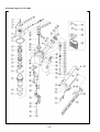
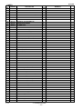
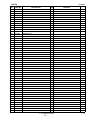
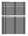
1
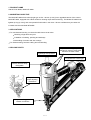
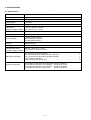
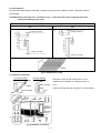
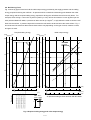
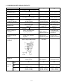
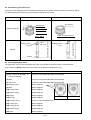
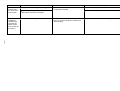
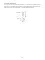
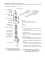
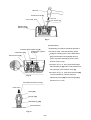
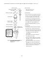
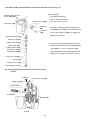
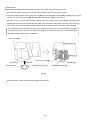
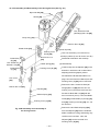
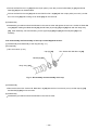
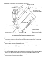
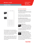
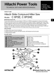
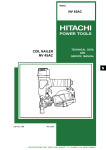
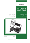
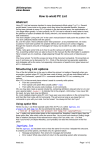
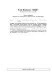
MODEL
NT 65MA
POWER TOOLS
FINISH NAILER
NT 65MA
TECHNICAL DATA
AND
SERVICE MANUAL
N
LIST No. 1093
Dec. 1999
SPECIFICATIONS AND PARTS ARE SUBJECT TO CHANGE FOR IMPROVEMENT
REMARK:
Throughout this TECHNICAL DATA AND SERVICE MANUAL, a symbol(s)
is(are) used in the place of company name(s) and model name(s) of our
competitor(s). The symbol(s) utilized here is(are) as follows:
Competitors
Symbols Utilized
Company Name
Model Name
T
SENCO
SFN40
P
BOSTITCH
N60FN
Notice for use
Specifications and parts are subject to change for improvement.
Refer to Hitachi Power Tool Technical News for further information.
CONTENTS
[ Business Section ]
Page
1. PRODUCT NAME
••••••••••••••••••••••••••••••••••••••••••••••••••••••••••••••••••••••••••••••••••••••••••••••••••••••••••••••••••••••
2. MARKETING OBJECTIVE
3. APPLICATIONS
1
• • • • • • • • • • • • • • • • • • • • • • • • • • • • • • • • • • • • • • • • • • • • • • • • • • • • • • • • • • • • • • • • • • • • • • • • • • • • • • • • • • • • • • • • • • • • • • • • • • • • • • • • •
1
• • • • • • • • • • • • • • • • • • • • • • • • • • • • • • • • • • • • • • • • • • • • • • • • • • • • • • • • • • • • • • • • • • • • • • • • • • • • • • • • • • • • • • • • • • • • • • • • • • • • • • • • • • • • • • • • • • • • • • • • •
1
4. SELLING POINTS
• • • • • • • • • • • • • • • • • • • • • • • • • • • • • • • • • • • • • • • • • • • • • • • • • • • • • • • • • • • • • • • • • • • • • • • • • • • • • • • • • • • • • • • • • • • • • • • • • • • • • • • • • • • • • • • • • • • • • •
5. SPECIFICATIONS
5-1. Specifications
5-2. Nail Selection
5-3. Examples of Nail Use
5-4. Nail Driving Force
1
• • • • • • • • • • • • • • • • • • • • • • • • • • • • • • • • • • • • • • • • • • • • • • • • • • • • • • • • • • • • • • • • • • • • • • • • • • • • • • • • • • • • • • • • • • • • • • • • • • • • • • • • • • • • • • • • • • • • • •
2
•••••••••••••••••••••••••••••••••••••••••••••••••••••••••••••••••••••••••••••••••••••••••••••••••••••••••••••••••••••••
2
•••••••••••••••••••••••••••••••••••••••••••••••••••••••••••••••••••••••••••••••••••••••••••••••••••••••••••••••••••••••
3
••••••••••••••••••••••••••••••••••••••••••••••••••••••••••••••••••••••••••••••••••••••••••••••••••••••••••••
3
•••••••••••••••••••••••••••••••••••••••••••••••••••••••••••••••••••••••••••••••••••••••••••••••••••••••••••••••••
4
6. COMPARISONS WITH SIMILAR PRODUCTS
7. PRECAUTIONS IN SALES PROMOTION
7-1. Instruction Manual
7-2. Warning Label
7-3. Related Laws and Regulations
• • • • • • • • • • • • • • • • • • • • • • • • • • • • • • • • • • • • • • • • • • • • • • • • • • • • • • • • • • • • • • • • • • • • • • • • • • •
5
• • • • • • • • • • • • • • • • • • • • • • • • • • • • • • • • • • • • • • • • • • • • • • • • • • • • • • • • • • • • • • • • • • • • • • • • • • • • • • • • • •
6
••••••••••••••••••••••••••••••••••••••••••••••••••••••••••••••••••••••••••••••••••••••••••••••••••••••••••••••••
••••••••••••••••••••••••••••••••••••••••••••••••••••••••••••••••••••••••••••••••••••••••••••••••••••••••••••••••••••••
••••••••••••••••••••••••••••••••••••••••••••••••••••••••••••••••••••••••••••••••••••••••••••••
8. MECHANISM AND OPERATION PRINCIPLE
8-1. Mechanism
8-2. Valve Bushing (B) and Plunger
8-3. Interchangeability of Parts
8-4. Operation Principle
6
6
7
• • • • • • • • • • • • • • • • • • • • • • • • • • • • • • • • • • • • • • • • • • • • • • • • • • • • • • • • • • • • • • • • • • • • • • • • • • • • •
8
• • • • • • • • • • • • • • • • • • • • • • • • • • • • • • • • • • • • • • • • • • • • • • • • • • • • • • • • • • • • • • • • • • • • • • • • • • • • • • • • • • • • • • • • • • • • • • • • • • • • • • • • • • • • • • • • • • • • • • • • • •
8
••••••••••••••••••••••••••••••••••••••••••••••••••••••••••••••••••••••••••••••••••••••••••••••
10
• • • • • • • • • • • • • • • • • • • • • • • • • • • • • • • • • • • • • • • • • • • • • • • • • • • • • • • • • • • • • • • • • • • • • • • • • • • • • • • • • • • • • • • • • • • • • • • • • • • • •
10
•••••••••••••••••••••••••••••••••••••••••••••••••••••••••••••••••••••••••••••••••••••••••••••••••••••••••••••••
11
[ Service Section ]
9. TROUBLESHOOTING GUIDE
9-1. Troubleshooting and Correction
9-2. Regrinding the Driver Blade
9-3. Possible Cause and Correction of Air Leakage
• • • • • • • • • • • • • • • • • • • • • • • • • • • • • • • • • • • • • • • • • • • • • • • • • • • • • • • • • • • • • • • • • • • • • • • • • • • • • • • • • • • • • • • • • • • • • • • • • • • •
13
• • • • • • • • • • • • • • • • • • • • • • • • • • • • • • • • • • • • • • • • • • • • • • • • • • • • • • • • • • • • • • • • • • • • • • • • • • • • • • • • • • • • • • • • • • • • •
13
•••••••••••••••••••••••••••••••••••••••••••••••••••••••••••••••••••••••••••••••••••••••••••••••••••
17
• • • • • • • • • • • • • • • • • • • • • • • • • • • • • • • • • • • • • • • • • • • • • • • • • • • • • • • • • • • • • • • • • • • • • • •
10. DISASSEMBLY AND REASSEMBLY
10-1. General Precautions in Disassembly and Reassembly
10-2. Disassembly and Reassembly of the Output Section
10-3. Disassembly and Reassembly of the Control Valve Section
10-4. Disassembly and Reassembly of the Driving Section
10-5. Disassembly and Reassembly of the Cap and the Magazine Section
18
•••••••••••••••••••••••••••••••••••••••••••••••••••••••••••••••••••••••••••••••••••••••
20
••••••••••••••••••••••••••••••••••••••••••••••••••••••••••
20
• • • • • • • • • • • • • • • • • • • • • • • • • • • • • • • • • • • • • • • • • • • • • • • • • • • • • • • • • • • • •
21
• • • • • • • • • • • • • • • • • • • • • • • • • • • • • • • • • • • • • • • • • • • • • • • • • • •
24
• • • • • • • • • • • • • • • • • • • • • • • • • • • • • • • • • • • • • • • • • • • • • • • • • • • • • • • • • • • •
27
• • • • • • • • • • • • • • • • • • • • • • • • • • • • • • • • • • • • •
28
••••••••••••••••••••••••••••••••••••••••••••••••••
30
11. INSPECTION AND CONFIRMATION AFTER REASSEMBLY
12. STANDARD REPAIR TIME (UNIT) SCHEDULES
• • • • • • • • • • • • • • • • • • • • • • • • • • • • • • • • • • • • • • • • • • • • • • • • • • • • • • • • • • • • • • • • • • • • •
31
[ Appendix ]
Assembly Diagram for NT 65MA
•••••••••••••••••••••••••••••••••••••••••••••••••••••••••••••••••••••••••••••••••••••••••••••••••••
32
1. PRODUCT NAME
Hitachi Finish Nailer, Model NT 65MA
2. MARKETING OBJECTIVE
The Model NT 65MA finish nailer (angle type 15 Ga. x 65 mm (2-1/2")) is an upgraded version of the current
Model NT 65AA, equipped with a blow nozzle for cleaning chips while nail driving. The Model NT 65MA is the
lightest (2.0 kg (4.4 lbs.)) and most powerful finish nailer in this class. We are confident that your sales will
increase with the new Model NT 65MA.
3. APPLICATIONS
For manufactured housing, on-site and mobile home construction:
Mounting of light and heavy trim
Installation of molding, paneling and stairways
Assembling of window and door casings
For cabinet-making, furniture-making and woodworking
4. SELLING POINTS
Capable of cleaning chips and
sawdust of course it drives nails
thanks to the blow nozzle
Lightweight and powerful
Equipped with a racket grip
For comfort
Exhaust direction easily
changeable
Simple drivedepth adjusting
mechanism
Easy-to-use clogged nail
release mechanism
--- 1 ---
5. SPECIFICATIONS
5-1. Specifications
Model
NT 65MA
Driving system
Reciprocating piston type
Operating pressure
5 --- 8.5 kgf/cm2 (70 --- 120 psi, 4.9 --- 8.3 bar) (Gauge pressure)
Driving speed
3 pcs./sec
Weight
2.0 kg (4.4 lbs.)
Dimensions
(Length x Height x Width)
344 mm x 305 mm x 82 mm
(13-17/32" x 12" x 3-7/32")
Nail feed system
Ribbon spring
Nail capacity
100 nails
Air consumption
1.20 ltr/cycle at 7 kgf/cm2
(0.042 ft3/cycle at 100 psi)
(1.20 ltr/cycle at 6.9 bar)
Air inlet
3/8 NPT thread
Packaging
Corrugated cardboard box (Sleeve type)
Package dimensions
(Length x Height x Width)
430 mm x 380 mm x 113 mm
(16-15/16" x 14-15/32" x 4-7/16")
Standard accessories
Eye protector (Code No. 875769)
Hex. bar wrench for M5 screw (Code No. 944458)
Hex. bar wrench for M6 screw (Code No. 944459)
Case (Code No. 881775)
Nose cap (A) (Code No. 881751)
• • • • • • • • • • • • • • • • • • • • • • • • • • • • • • • • • • • • • • • • • • • • • • • • • • • • • • • • • • • • • • • • • • • • •
• • • • • • • • • • • • • • • • • • • • • • • • • • • • • • • • • • • • • • • • • • • • •
• • • • • • • • • • • • • • • • • • • • • • • • • • • • • • • • • • • • • • • • • • • • •
• • • • • • • • • • • • • • • • • • • • • • • • • • • • • • • • • • • • • • • • • • • • • • • • • • • • • • • • • • • • • • • • • • • • • • • • • • • • • • • • •
• • • • • • • • • • • • • • • • • • • • • • • • • • • • • • • • • • • • • • • • • • • • • • • • • • • • • • • • • • • • • • • • • • • • •
Optional accessories
Sequential trip mechanism kit (Single shot)
Pneumatic tool lubricant (1 oz oil feeder)
Pneumatic tool lubricant (4 oz oil feeder)
Pneumatic tool lubricant (1 quart can)
--- 2 ---
(Code No. 880414)
(Code No. 877153)
(Code No. 872042)
(Code No. 876212)
1
1
1
1
1
5-2. Nail Selection
The Model NT 65MA utilizes small-head, T-shaped nails (finish nails) collated by tapes. Applicable nails are
shown below.
CAUTION: Ensure that nails are as specified in Fig. 1. Other nails will cause clogging of nails and
subsequent damage to the nailer.
15-gauge finish nail (collating angle 34˚)
Max.
0.12"
(3.0 mm)
Min.
0.072" (1.8 mm)
0.045"
(1.1 mm)
0.095" (2.4 mm)
2 -1/2" (65 mm)
0.045"
(1.1 mm)
0.12"
1 -1/4" (32 mm) (3.0 mm)
0.095" (2.4 mm)
0.072" (1.8 mm)
34˚
Tapes
Fig. 1 Dimensions of nails
5-3. Examples of Nail Use
B: Base molding
A: Crown molding
Nail
Ceiling
Examples of uses for the nails shown in 5-2 for
Wall
installing finish materials, or molding as shown in
Base molding
Fig. 2.
Typical mounting methods are shown in circles A and B.
Nail
Crown molding
Nail
A
Floor
Wall
Bed
Corner guard
Cove
Crown
Casing
Lattice
Rabbeted
stool
Batten
Flat stool
Base cap
Chair rail
B
Ply cap
Base molding
Base shoe
Wainscot
Fig. 2 Examples of molding
--- 3 ---
5-4. Nail Driving Force
Fig. 3 shows by type of wood and nail the nailer output energy provided by the supply pressure and the nailing
energy required for driving the nail flush. Air pressure which exceeds the intersecting point between the nailer
output energy and the required nailing energy required for driving the nail allows the nail to be fully driven. For
example, when driving a 1.8 mm dia. by 65 mm (5/64" by 2-1/2") nail into six sheets of 12 mm plywood (72 mm
thick) with the Model NT 65MA, a pressure of about 6.3 bar (6.4 kgf/cm2, 91 psi) allows the nailer to drive the nail
flush with the surface. A pressure beyond this causes the nail head to be driven below the wood surface. Fig. 3
should be used as reference data because those values vary depending on the type of wood, moisture content,
and grain of wood.
Required nailing energy
Nailer output energy
(J)
(ft-lb)
(kgf•cm))
(J)
(ft-lb)
(kgf•cm))
60
60
80
80
Plywood (12 mm thick) x 6
800
NT65MA
800
NT65AA
60
60
600
O
600
40
40
40
40
400
400
P
20
20
20
0
200
100
50
200 (mm2)
150
0.15
0.10
0.20
0.25
20
0
0.30
4
5
4
5
6
6
7
8
7
8
1.8 mm x 65 mm (0.072 x 2-1/2")
1.8 mm x 57 mm (0.072 x 2-1/4")
1.8 mm x 50 mm (0.072 x 2")
1.8 mm x 45 mm (0.072 x 1-3/4")
1.8 mm x 38 mm (0.072 x 1-1/2")
1.8 mm x 32 mm (0.072 x 1-1/4")
(in2)
Size of nail
200
60
Nail : d x L
(mm x mm)
L
70
80
90
100
110
8.3 (bar)
8.5
(kgf/cm2)
120
(psi)
Air pressure setting to drive nail flush with NT 65MA
d
Fig. 3 Required nailing energy and nailer output energy
--- 4 ---
6. COMPARISONS WITH SIMILAR PRODUCTS
HITACHI
Maker
NT 65MA
Model name
Operating pressure
NT 65AA
5 --- 8.5 kgf/cm2
(70 --- 120 psi)
2.0 kg (4.4 lbs.)
Weight
Dimensions (L x H x W)
Air consumption
at 7 kgf/cm2 (100 psi)
344 mm x 305 mm x 82 mm
(13-17/32" x 12" x 3-7/32")
1.20 ltr/cycle
Blow nozzle
P
5 --- 8.5 kgf/cm2
(70 --- 120 psi)
5 --- 7 kgf/cm2
(70 --- 100 psi)
2.17 kg (4.7 lbs.)
1.95 kg (4.4 lbs.)
330 mm x 286 mm x 89 mm
359 mm x 276 mm x 76 mm
(13" x 11-1/4" x 3-1/2")
(14-1/8" x 10-7/8" x 3")
1.25 ltr/cycle
3
1.31 ltr/cycle
(0.042 ft /cycle)
(0.044 ft /cycle)
(0.046 ft3/cycle)
100 pcs.
100 pcs.
100 pcs.
Rear loading type
Angle: 34˚
Rear loading type
Angle: 34˚
Rear loading type
Angle: 26˚
None
None
Nail capacity
Magazine type
1.9 kg (4.2 lbs.)
T
None
Provided
3
Direction change of
exhaust air
Easily changeable 360˚
by turning by hand
Only 4 directions
by 90˚each by
replacing the piece
Changeable 360˚,
but requires a hex.
bar wrench
Clogged nail release
method
Single-touch operation
by hand
Single-touch
operation by hand
Prying out with a
flat-blade screwdriver
With an easy-to-adjust scale
No scale
No scale
Racket grip
(Easy to grip)
Hook and loop tape
type (Slippery)
Rubber
(Unpleasant touch)
34˚
34˚
26˚
Driving depth adjustment
mechanism
Adjusting
scale
Handle grip
Collating
angle
Applicable
nails
Dia.
Length
2.4 mm --- 3.0 mm (#15)
(.095" --- .12")
32 mm --- 65 mm
(1-1/4" --- 2-1/2")
--- 5 ---
2.4 mm --- 3.0 mm (#15) 2.4 mm --- 3.0 mm (#15)
(.095" --- .12")
(.095" --- .12")
32 mm --- 65 mm
(1-1/4" --- 2-1/2")
32 mm --- 65 mm
(1-1/4" --- 2-1/2")
7. PRECAUTIONS IN SALES PROMOTION
In the interest of promoting the safest and most efficient use of the Model NT 65 MA Nailer by all of our
customers, it is very important that at the time of sale the salesperson carefully ensures that the buyer seriously
recognizes the importance of the contents of the Instruction Manual, and fully understands the meaning of the
precautions listed on the Warning Label attached to each tool.
The standard Model NT65MA is intended for continuous nail driving. (Note that the Model NT65MA is single-shot
type in some areas.) Salespersons must advise the customers that the sequential trip mechanism kit, which can
change the Model NT 65MA into a single-shot type, is available as an option (and change the Model NT 65MA
when there is a customer’s need). Refer to the leaflet attached to the Instruction Manual.
7-1. Instruction Manual
Although every effort is made in each step of the design, manufacture, and inspection to provide protection
against safety hazards, the dangers inherent in the use of any pneumatic tool cannot be completely eliminated.
Accordingly, general precautions and suggestions for use of pneumatic tools, and specific precautions and
suggestions for the use of the pneumatic nailer are listed in the Instruction Manual to enhance the safe, efficient
use of the tool by the customer. Salespersons must be thoroughly familiar with the contents of the Instruction
Manual to be able to offer appropriate guidance to the customers during sales promotion.
7-2. Warning Label
Each Model NT 65MA unit is provided with a Warning Label (illustrated below) which lists basic safety precautions
in its use. Carefully ensure that customers fully understand and follow these precautions before using the tool.
READ INSTRUCTION MANUAL before use.
Failure to follow instructions WILL RESULT IN SERIOUS INJURY.
Operator and others in work area
MUST WEAR ANSI-REQUIRED
EYE PROTECTOR.
NEVER USE BOTTLED GASES.
Use regulated air only.
DO NOT EXCEED 120 psi/8.3 bar.
NEVER CARRY WITH FINGER ON TRIGGER.
DISCONNECT AIR before servicing,
unjamming or when not in use.
--- 6 ---
7-3. Related Laws and Regulations
As nailers and staplers are designed to instantaneously drive nails and staples, there is an ever-present danger of
misfiring and subsequent possible serious injury. Accordingly, close attention in handling is absolutely necessary
at all times. Carefully ensure that the customer is fully aware of the precautions listed in the Instruction Manual
provided with each unit.
While there are no specific safety regulations, there are related items in various general safety regulations with
which the salespersons should be familiar in order to properly advise the customer. Please check your national
and/or local regulations for applicable items.
Some applicable items are outlined below.
The U.S.A.:
OSHA
1926.102 Eye and face protection
1962.302 Power-operated hand tools
ANSI SNT-101-1993
Portable, Compressed-Air-Actuated,
Fastener Driving Tools-Safety Requirements for
--- 7 ---
8. MECHANISM AND OPERATION PRINCIPLE
8-1. Mechanism
Most of the parts of the output section have been newly designed for the addition of the blow nozzle function,
though its basic construction is the same as that of the Model NT 65AA.
Primary differences from the Model NT 65AA are described below.
Output section
• • • • • • • • • • • • •
The exhaust cover, nose, valve bushing, plunger, valve packing, knob and spring have
been newly designed for the blow nozzle function. The top cover and plate are
common to the Models NR 90AC and NV 65AH.
--- 8 ---
Nose [6]
Valve Packing [19]
O-Ring (1AP-3) [22]
Valve Piston [66]
O-Ring (S3) [23]
Plunger Spring [68]
Valve Bushing (B)
[62]
Accumulator
Spring [20]
Plunger [21]
O-Ring (S-10) [24]
Plunger [70]
Valve Bushing [25]
Valve Bushing (A) [71]
Cross-sectional view of blow nozzle
Control valve section
Body Ass’y [34]
Top Cover [3]
Exhaust Cover [5]
Exhaust Vent
Knob [26]
Output section
Exhaust Valve
Rubber (A) [8]
Cap (A) [53]
Magazine Cover
[72]
Control valve
section
Head Valve
Rubber (A) [13]
Accumulator
Trigger (A) [57]
Cylinder [15]
Piston
Bumper [30]
Nail Stopper [82]
Driving section
Guide Plate
(B) [35]
Nail Rail [79]
Magazine [83]
Lock Lever [38]
Magazine section
Guide Plate (A) [37]
Pushing Lever
(A) [46]
Nail Feeder (B) [78]
Nail Feeder (A) [76]
--- 9 ---
Fig. 4 Construction
8-2. Valve Bushing (B) and Plunger
Among the newly designed parts, the difference between the new design and the current one are shown below,
for valve bushing (B) and the plunger because their shapes are so similar.
Newly designed part
Current part (NV 50AE, NV 50AG)
4
0.3
Color: Aluminum (Silver)
O-Ring groove
(2 pcs.)
Hole
(Dia. 0.2 mm)
Plunger
Groove
Overall length: 33.9 mm
Color : Black
O-Ring groove
(1 pc.)
Overall length: 38 mm
Valve bushing (B)
No notches.
Notches are
added (4 pcs.).
(Width: 4 mm,
depth: 0.3 mm)
8-3. Interchangeability of Parts
The parts which are not interchangeable with those of the Model NT 65AA are given in the table below.
(The numbers in [Bold] indicate the item numbers in the Model NT 65MA Parts List.)
Parts
[1] Hex. Socket Hd. Bolt M6 x 16
Common to the Models NR 90AC and NV 65AH
(for Top Cover [3])
[2] Plate
Common to the Models NR 90AC and NV 65AH
[3] Top Cover
Common to the Models NR 90AC and NV 65AH
[5] Exhaust Cover
Newly designed
[6] Nose
Newly designed
[18] Caution Plate
Newly designed
[19] Valve Packing
Newly designed
[20] Spring
Newly designed
[21] Plunger
Newly designed
[22] O-Ring (1AP-3)
Common to the Model NT 50AD
[23] O-Ring (S3)
Newly designed
[24] O-Ring (S-10)
Newly designed
[25] Valve Bushing
Newly designed
[26] Knob
Newly designed
--- 10 ---
NT 65MA
NT 65AA
8-4. Operation Principle
Exhaust Valve Rubber (A) [8]
(1) Before nailing: (Fig. 5, Fig. 6)
Exhaust vent
1) When compressed air is fed to the main body, it fills
the Accumulator (
Head valve chamber
Head Valve
Spring [9]
).
2) At the same time, the compressed air flows into the
Air passage
Head Valve[11]
valve piston lower chamber of the control valve
Control
valve
section
Accumulator
section and forces the Valve Piston [66] upward.
Also, the compressed air is fed through the air
Piston [29]
supply vent and air passage to the head valve
Cylinder [15]
chamber. As a result, the Head Valve Spring [9] is
Cylinder hole
pushed down together to seal the Head Valve [11]
Trigger (A) [57]
Return air
chamber
and Cylinder [15].
(2) When nailing: (Fig. 5, Fig. 6)
1) When Pushing Lever (A) [46] and Trigger (A) [57]
are operated together and the Plunger [70] is
pushed upward, the compressed air in the valve
Pushing Lever (A) [46]
Nail
piston lower chamber is discharged from the bottom
Fig. 5
of the Plunger [70]. As a result, the compressed air
in the accumulator (
) pushes down the Valve
Piston [66], blocking the air supply vent and opening
the exhaust valve.
2) When the exhaust valve opens, the compressed air
in the feed valve chamber is discharged into the
To the head valve chamber
atmosphere through the air passage.
3) When the air pressure applied on the bottom surface
of the Head Valve [11] overcomes the strength of the
Air
passage
Air supply
vent
Accumulator
Head Valve Spring [9], the Head Valve [11] is
pushed upward. At this time, the Head Valve [11]
Exhaust
valve
seals with Exhaust Valve Rubber (A) [8], blocking
the passage to the exhaust vent.
4) When the Head Valve [11] goes up, the compressed
Valve Piston [66]
air in the accumulator flows rapidly into the Cylinder
[15], forcing the Piston [29] downward to strike the
nail. When the Piston [29] passes the cylinder hole,
the compressed air flows into the return air chamber
and is accumulated there.
--- 11 ---
Valve piston lower
chamber
Plunger [70]
Fig. 6 Control valve section
(3) During return: (Fig. 7, Fig. 8)
Exhaust Valve Rubber (A) [8]
1) When either Pushing Lever (A) [46] or Trigger (A)
Head valve chamber
Exhaust vent
[57] is released, the Plunger [70] goes down and the
compressed air in the accumulator flows into the
Accumulator
Air passage
Head Valve [11]
valve piston lower chamber.
2) As the air pressure in the valve piston lower chamber
Control
valve
section
Cylinder [15]
increases to overcome the air pressure applied on
Return air
chamber
the upper portion of the Valve Piston [66], the Valve
Piston [66] is forced upward. When this occurs, the
Piston [29]
exhaust valve is closed and the air supply vent is
Trigger (A) [57]
opened.
Piston
Bumper [30]
3) When the air supply vent opens, the compressed air
in the accumulator (
) passes through the air
passage and flows into the head valve chamber to
Driver blade
push down the Head Valve [11]. As a result, the
Head Valve [11] and Cylinder [15] are sealed and,
Pushing Lever (A) [46]
at the same time, the Head Valve [11] and Exhaust
Valve Rubber (A) [8] are released to open the
Fig. 7
exhaust vent.
4) The compressed air at the upper portion of the
Piston [29] is discharged into the atmosphere
through the exhaust vent. In this way, the air
pressure at the upper portion of the Piston [29] is
To the head valve chamber
reduced, and the greater pressure of the air
accumulated in the return air chamber pushes the
Piston [29] upward.
Air supply vent
5) If the air pressure at the lower portion of the Piston
Accumulator
Air
passage
[29] is higher than that of the atmosphere after the
Piston [29] has fully returned, the excess air
pressure is discharged into the atmosphere through
the clearance between the Piston Bumper [30] and
the driver blade.
Exhaust valve
Valve Piston [66]
Valve piston lower
chamber
Plunger [70]
Fig. 8 Control valve section
--- 12 ---
9. TROUBLESHOOTING GUIDE
9-1. Troubleshooting and Correction
Problem
1) Nails cannot
be driven.
Possible cause (*: most-common cause)
< Nails >
The magazine is not loaded with specified
genuine nails.
The magazine is loaded with abnormal nails
(bent nails, abnormal collation, other).
<Magazine>
Nail feeder abnormal (burrs, deformed,
damaged).
Ribbon spring abnormal (fatigued,
damaged).
Magazine groove too wide or too narrow.
Nail rail groove width too wide or too narrow.
Inspection methods
Check if the magazine is normally loaded
with specified genuine nails.
Remedy
Use specified genuine nails.
Remove the abnormal nails and load the magazine
with normal nails.
Check the nail feeding section for abnormal
conditions (burrs, fatigued, deformed,
damaged).
Correct the burred or deformed portion.
Replace the defective part.
Replace the defective part.
Check if they move smoothly after loading
nails and check if the nail feeder operates
smoothly.
Replace the defective part.
Replace the defective part.
--- 13 ---
Nail groove in the blade guide abnormal (burrs).
Replace the defective part.
Magazine cover abnormal (deformed,
damaged).
* Adhesive fragments and wood chips are on
the magazine, nail feeder or nail rail.
<Output section: piston, driver blade, etc.>
Air pressure too low.
* Piston ring worn.
Nail rail
Oil
After removing the adhesive fragments and wood
chips, apply oil to the nail rail.
Keep the nail feeder in the back position
after pulling it backward and release the
lock lever for idle driving. Then, check if the
driver blade and guide plate (A) have
returned.
* Piston bumper abnormal.
Adjust for 5 to 8.5 kgf/cm2 (4.9 --- 8.3 bar, 70 --- 120 psi).
Replace the piston ring.
Replace the piston bumper.
The O-ring of the cylinder is abnormal
(dislocated, deformed, damaged).
Reassemble or replace.
Driver blade abnormal (deformed, burrs,
damaged).
Bumper sheet abnormal (square hole worn,
damaged).
Cylinder's internal surface abnormal
(deposits of dirt, worn).
Touch up or replace.
Replace the part.
Check if nails can be driven at 5 kgf/cm2
(4.9 bar, 70 psi).
After removing the dirt, apply oil or replace.
Problem
1) Nails cannot
be driven.
Possible cause (*: most-common cause)
Head valve sliding surface abnormal
(uneven, damaged, oiling needed).
Inspection methods
While idle driving, check if the driving
operation takes place.
Head valve rubber abnormal (torn,
damaged).
While idle driving, check if the driver blade is
held down.
2) Nails bent
while being
driven.
Replace the part.
--- 14 ---
After making idle driving, check if the driver
blade keeps the down position.
Replace the part.
O-ring worn or oiling needed.
Disassemble the control valve and check
the O-ring.
Apply grease.
For short nails, the adjuster is raised too
high.
Check if the adjuster is raised too high.
Turn the adjuster for lower (lower the pressure).
Nails are not fully fed into the ejecting port.
See item 1).
See item 1).
Unspecified nails used.
See item 1).
See item 1).
Check if the driver blade tip is abnormally
worn.
Replace the part.
Regrind (see 9-2, "Regrinding the Driver Blade").
The material being driven into is very hard.
Check if a nail is bent even when driven into
soft wood.
Unusable because the tool is not designed for
such usage.
The adjuster is improperly adjusted.
Turn the adjuster to the lowest position, then
drive.
Adjust the adjuster for the proper position.
* Driver blade worn.
3) The driven nail
is driven into
the material
but the head is
raised above
the surface.
Replace the part.
Apply grease.
Replace the part.
Abnormal spring in head valve (fatigued,
damaged).
<Control valve section>
Abnormal plunger, valve piston, valve
bushing (A) or valve bushing (B) (burrs,
damaged).
Remedy
Air pressure too low.
The material being driven into is very hard.
* Driver blade worn.
Adjust for 5 to 8.5 kgf/cm2 (4.9 --- 8.3 bar, 70 --- 120
psi).
Drive the nail into soft wood and check if the
head is raised or not.
Unusable because the tool is not designed for
such usage.
Check if the driver blade tip is worn.
Replace the part.
Regrind (see 9-2, "Regrinding the Driver Blade").
Problem
Possible cause (*: most-common cause)
3) The driven nail * Piston ring is abnormal (worn, damaged).
is driven into
the material
but the head is
Cylinder’s internal surface abnormal (worn,
raised above
rough).
the surface.
--- 15 ---
4) Nails clog the
mechanism.
Inspection methods
Disassemble the output section and check
the piston ring and the internal surface of
the cylinder for abnormal condition.
Remedy
Replace the defective part.
Replace the defective part.
Exhaust valve rubber abnormal (worn,
damaged, flaws on seal surface).
Disassemble and check the exhaust valve
rubber part for abnormal condition.
Replace the defective part.
Head valve sliding surface abnormal
(uneven, damaged, oiling needed).
Check the sliding surface for abnormal
conditions and need of oiling.
Replace the defective part.
Apply grease.
Unspecified nails used.
Check if the nails are specified ones.
Use specified genuine nails.
Check if they move smoothly after loading
nails, and check if the nail feeder operates
smoothly.
See <Magazine> in item 1).
Check if the driver blade tip is worn.
Replace the part.
Regrind (see 9-2, "Regrinding the Driver Blade").
Perform idle driving or actually drive with
nails, and check if the driver blade returns
completely.
See <Output section: piston, driver blade, etc.> in
item 1).
<Improper nail feed>
See <Magazine> in item 1).
Driver blade worn.
<The driver blade does not return
completely.>
See <Output section: piston, driver blade,
etc.> in item 1).
Problem
5) Air keeps
blowing from
the nose of the
blow nozzle.
6) Air blow is
stopped or
weakened by
pressing the
button of the
blow nozzle all
the way in.
Possible cause (*: most-common cause)
Spring is abnormal (fatigued, damaged).
Inspection methods
Press the button of the blow nozzle to check
if it operates smoothly.
* The O-ring of the plunger is abnormal
(dislocated, deformed, damaged).
Insufficient press-fitting of the button.
Remedy
Replace the spring.
Reassemble or replace.
Press the button of the blow nozzle all the
way in to check if the button contacts the
valve bushing.
Press-fit the button (knob) into the proper position.
--- 16 ---
9-2. Regrinding the Driver Blade
The tip of the driver blade should be ground as shown in Fig. 9. To grind with a grinder, gradually grind the tip
while cooling the ground area with water to prevent it from being excessively heated. Excessive grinding will
rapidly reduce the service life of the driver blade. In such a case, replace the driver blade.
Driver blade
3˚ 30"
Fig. 9
--- 17 ---
9-3. Possible Cause and Correction of Air Leakage
Air leakage repair location
Repair procedure
(G)
(A)
(1) Check the points of the
a
(D)
following parts marked
(D)
b
c
by an asterisk for
abnormal condition.
(B)
(2) Next, check the seal
parts marked with a
double circle for wear,
flaws and damage.
d
(3) And then, check other
places.
Control valve section
f
e
(C)
(E)
(F)
Air leakage points
Possible cause
With control valve OFF
A) Exhaust port
The O-Ring [10] of the Head Valve
[11] is abnormal or its sliding surface,
or part a is worn, deformed or
flawed.
Head Valve Rubber (A) [13] is
abnormal or its sliding surface, or
part b of the Cylinder [15] is worn
or flawed.
B) Exhaust cover
Hex. Socket Hd. Bolt M6 x 16 [1] is
loose.
The Gasket [7] is damaged.
The seal surface of the Body Ass’y
[34] or Exhaust Cover [5] is
abnormal.
--- 18 ---
With control valve ON
Exhaust Valve Rubber (A) [8] is
abnormal or its sliding surface, or part
c of the Head Valve [11] is worn or
flawed.
Air leakage points
Possible cause
With control valve OFF
C) Blade guide
The Cylinder O-Ring [16] is abnormal
(broken, flawed).
D) Nose, valve bushing
The Valve Packing [19] is damaged.
The O-Ring (1AP-3) [22] of the
Plunger [21] is abnormal (worn,
broken, flawed).
The O-Ring (S3) [23] of the Plunger
[21] is abnormal (worn, broken,
flawed).
The screw of the Valve Bushing [25]
is loose.
With control valve ON
The Piston Bumper [30] is abnormal
(part d damaged, deformed or
cracked).
The Piston [29] is abnormal (driver
blade deformed, seal surface
deformed).
E) Control valve (I)
The O-Ring [67] of the Valve Piston
[66] is abnormal (worn, broken,
flawed).
The O-Ring [64] of the Valve Piston
[66] is abnormal (worn, broken,
flawed).
The O-Ring (S-18) [63] is abnormal
(broken, flawed).
* The internal surface (part e ) of the
valve cavity of the Body Ass’y [34] is
abnormal.
The O-Ring [64] (upper side) of the
Valve Piston [66] is abnormal (worn,
broken, flawed).
The Head Valve O-Ring [61] of Valve
Bushing (B) [62] is abnormal (broken,
flawed).
* The valve room upper surface f of
the Body Ass’y [34] is abnormal.
F) Control valve (II)
The O-Ring [69] (lower side) of the
Plunger [70] is abnormal (worn,
broken, flawed).
The Valve Bushing (A) [71] is
abnormal (Plunger [70] sliding
surface e deformed or flawed).
The O-Ring [69] (upper side) of the
Plunger [70] is abnormal (worn,
broken, flawed).
The Valve Piston [66] is abnormal
(plunger sliding surface deformed or
flawed).
G) Cap (A) [53]
Gasket (B) [52] is damaged.
The Hex. Socket Hd. Bolt M5 x 16 [54] is loose.
The seal surface of the Body Ass’y [34] or Cap (A) [53] is abnormal (damaged,
deformed, flawed).
--- 19 ---
10. DISASSEMBLY AND REASSEMBLY
The items particularly necessary for disassembly and reassembly are described below. The [Bold] numbers in
the descriptions below correspond to the item numbers in the Parts List and exploded assembly diagram.
[CAUTION]
Before disassembly or reassembly, be sure to disconnect the air hose from the nailer (with your
finger released from the trigger) to exhaust all the compressed air and remove all nails.
10-1. General Precautions in Disassembly and Reassembly
Apply grease (Nippeco SEP-3A) (Code No. 930035) to the O-ring and O-ring sliding portion. When installing the
O-ring, be careful not to damage the O-ring and prevent dirt entry.
Oil required: Hitachi pneumatic tool lubricant
1 oz (30 cc) Oil feeder (Code No. 877153)
4 oz (120 cc) Oil feeder (Code No. 874042)
1 quart (1 ltr) Can (Code No. 876212)
If the Gasket [7] is damaged, replace it and check that no air is leaking.
Be especially careful to prevent the entry of foreign particles into the control valve section.
Tightening torque for each part
Tightening torque N•m (kgf•cm, ft-lb)
Screw
Hex. Socket Hd. Bolt M6
•••••••••••••••••••••••••••••
[1], [36]
12.7
0.8 (130
8, 9.4
0.6)
Hex. Socket Hd. Bolt M5
•••••••••••••••••••••••••••••
[4], [54]
8.3
0.5 ( 85
5, 6.1
0.4)
•••••••••••••••••
[80]
8.3
0.5 ( 85
5, 6.1
0.4)
•••••••••••••••••••••••
[81]
2.0
0.5 ( 20
5, 1.5
0.4)
Hex. Socket Hd. Bolt (W/Flange) M5
Machine Screw (W/Washer) M5
--- 20 ---
10-2. Disassembly and Reassembly of the Output Section
(1) Disassembly and reassembly of the Exhaust Cover [5], Head Valve [11], Exhaust Valve Rubber (A) [8], Valve
Bushing [25], etc. (See Figs. 10, 11, 12 and 13.)
Valve Packing [19]
Hex. Socket Hd. Bolt
M6 x 16 [1]
Knob [26]
Valve Bushing [25]
Plate [2]
O-Ring (S-10) [24]
O-Ring (S3) [23]
O-Ring (1AP-3) [22]
Top Cover [3]
Hex. Socket Hd. Bolt
M5 x 20 [4]
Plunger [21]
Spring [20]
Exhaust Cover [5]
Nose [6]
[Tools required]
Hex. bar wrenches (5 mm and 4 mm)
Gasket [7]
Exhaust Valve
Rubber (A) [8]
Socket wrenches (14 mm and 10 mm)
Hammer
(a) Disassembly
Head Valve Spring [9]
Remove the four Hex. Socket Hd. Bolts M5 x 20 [4] with
a hex. bar wrench (4 mm).
O-Ring (S-34) [10]
Head Valve [11]
Cylinder O-Ring (C)
I.D 44.7 [12]
Head Valve
Rubber (A) [13]
The entire Exhaust Cover [5] can now be removed from
the Body Ass’y [34].
Remove the Hex. Socket Hd. Bolt M6 x 16 [1] with a hex.
bar wrench (5 mm). The Plate [2] and the Top Cover [3]
can now be removed.
Remove the Nose [6] with a socket wrench (10 mm) and
the Valve Bushing [25] with a socket wrench (14 mm).
The Valve Packing [19] and the Spring [20] can now be
removed.
Body Ass'y [34]
As shown in Fig. 11, insert a 4 to 5 mm dia. bar into the
5.5 mm dia. hole in the Exhaust Cover [5] and force out
the Exhaust Valve Rubber (A) [8] with a hammer. Now,
the parts forming the Exhaust Cover [5] can be taken out.
Fig. 10 Disassembly and reassembly of the
[CAUTION] To prevent damage to the Exhaust Valve
exhaust cover, head valve, exhaust
valve rubber (A), valve bushing, etc..
Rubber (A) [8], do not use a pointed bar or a
bar with a diameter of less than 4 mm.
--- 21 ---
Hammer
Exhaust Cover [5]
Force out
4 to 5 mm dia.
ba
5.5 mm dia. hole
r
Exhaust Valve
Rubber (A) [8]
Fig.11
(b) Reassembly
Disassembly procedures should be followed in
Exhaust Valve Rubber (A) [8]
Head Valve [11]
Charge with 3 grams
of grease.
Exhaust Cover [5]
the reverse order. Note the following points.
Charge the sliding portion of the Head Valve
[11] of the Exhaust Cover [5] with about 3
Push in
grams of grease and apply grease to each
surface of the O-rings.
As shown in Fig. 12, firmly push the Exhaust
Valve Rubber (A) [8] until it is fully seated over
the projection of the Exhaust Cover [5].
Push until the rubber is fully
seated over the projection.
As shown in Fig. 13, push down the Knob [26]
on a flat workbench until the clearance
Fig. 12
between the Knob [26] and the Plunger [21]
becomes 2 to 2.5 mm.
Push down as far as it will go.
Push down
Knob [26]
Plunger [21]
Valve Bushing [25]
Flat workbench
Fig. 13
--- 22 ---
(2) Disassembly and reassembly of the Cylinder [15], Piston [29], Piston Bumper [30], etc. (See Fig. 14.)
[Tools required]
Piston Ring [27]
Hex. bar wrench (4 mm)
O-Ring (I.D 34.2) [28]
Piston [29]
Flat-blade screwdriver
Retaining Ring [14]
(a) Disassembly
Remove the Exhaust Cover [5] as described in
section (1), remove the Retaining Ring [14] of
Cylinder [15]
the Body Ass’y [34], insert the blade of the
screwdriver into the retaining ring detaching
groove in the Body Ass’y [34], and remove the
Retaining Ring [14]. Now, the Cylinder [15],
Cylinder O-Ring
(I.D 63.1) [16]
Piston [29], Piston Bumper [30] (with the
Bumper Sheet [31] assembled), etc. can be
O-Ring (P-46) [17]
Piston Bumper [30]
taken out.
(b) Reassembly
Retaining ring
detaching groove
Disassembly procedures should be followed in
the reverse order. Note the following points:
Bumper Sheet [31]
Apply the supplied oil (Hitachi pneumatic tool
When assembling,
push in the
Cylinder [15] until
the Retaining Ring
[14] is surely
seated in the
groove in the Body
Ass’y [34].
lubricant) to the Piston Ring [27], O-Ring (I.D
34.2) [28], and the internal side of the
Cylinder [15].
Apply grease to the Cylinder O-Ring (I.D
63.1) [16] and then install.
Push in the Cylinder [15] until the Retaining
Body Ass’y [34]
Ring [14] is correctly seated in the groove in
Fig. 14 Disassembly and reassembly of
the cylinder, piston, piston
bumper, etc.
the Body Ass’y [34].
Remember that when putting the Retaining
Ring [14] into the groove in the Body Ass’y
[34], the opening of the Retaining Ring [14]
must not overlap with the retaining ring
detaching groove.
--- 23 ---
10-3. Disassembly and Reassembly of the Control Valve Section (See Fig. 15.)
[Tools required]
Retaining Ring (E-type)
for D6 Shaft [32]
Flat-blade screwdriver
Roll pin puller (3 mm dia.)
Roll Pin D3 x 28 [56]
Hex. bar wrench (4 mm)
Body Ass’y [34]
Trigger (A)
[57]
Trigger Pin
[58]
Remove the Retaining Ring (E-type) for D6
Shaft [32] with the blade of a screwdriver and
remove the Trigger Pin [58], and Trigger (A)
[57] can be removed.
Valve Bushing (B) [62]
O-Ring (S-18) [63]
O-Ring (I.D 8.8) [64]
To remove Trigger (A) [57] together with the
Valve Piston [66][
driving section (Pushing Lever (B) [42], Blade
O-Ring (I.D 8.8) [64]
Guide [43], etc.), remove Trigger (A) [57]
O-Ring (I.D 11) [67]
while forcing down the Plunger [70] with the
Plunger Spring [68]
blade of the screwdriver, as shown in Fig. 16.
O-Ring (I.D 1.8) [69]
Plunger [70]
O-Ring (I.D 1.8) [69]
Valve Bushing (A) [71][71]
Fig. 15 Disassembly and reassembly of the control valve
section
Remove
Pushing Lever (B) [42]
Trigger (A) [57]
Force down
Screwdriver
Plunger [70]
Fig. 16
--- 24 ---
Pull out the Roll Pin D3 x 28 [56] with the roll
pin puller (3 mm dia.), and take out the control
valve in the following manner.
Push
1) Remove the Exhaust Cover [5] by following the
4 - 5 mm dia. bar
procedure in (1), section 10-2.
Head Valve O-Ring
2) As shown in Fig. 17, put in the 4 --- 5 mm dia.
(I.D 16.8) [61]
bar from the upper side of the Body Ass’y [34]
Body Ass’y [34]
Valve Bushing
(B) [62]
and push the top of the Valve Piston [66].
Now, the parts forming the control valve can be
taken out except the Valve Bushing (A) [71]
and Head Valve O-Ring (I.D 16.8) [61].
Valve Piston [66]
[CAUTIONS]
Valve Bushing
(A) [71]
Plunger [70]
When
disassembling, do
not pull out this
part by gripping it
with pliers.
Be careful not to damage Valve Piston [66],
Valve Bushings (A) and (B) [71] and [62], etc.
Do not pull out the end of Plunger [70] with
Fig. 17
pliers.
3) To take out Valve Bushing (B) [62], put a 1.5 --Valve Bushing (B) [62]
3 mm dia. wire with its end hooked into the
hole in the bushing and pull it out while being
Pull out
careful not to damage the internal surface of
Hole
Be careful not to
damage the internal
surface.
Wire with 1.5 --- 3 mm
dia.
Fig. 18
--- 25 ---
Valve Bushing (B) [62], as shown in Fig. 18.
(b) Reassembly
Disassembly procedures should be followed in the reverse order. Note the following points:
Be extremely careful to prevent the entry of foreign particles into the control valve section.
Thoroughly apply grease to the O-Ring (I.D 1.8) [69] of the Plunger [70], O-Rings [64] and [67] (S-4), (I.D 8.8)
and (I.D 11) of the Valve Piston [66], and the shaft of the Plunger [70] shown in Fig. 19.
As shown in Fig. 19, install Valve Bushing (A) [71] so that the roll pin groove in Valve Bushing (A) [71] will be
aligned with the roll pin hole in the Body Ass’y [34]. First, insert the roll pin puller (3 mm dia.) into the roll pin
hole. Then, upon confirming that the puller \passes through the hole, drive in the Roll Pin D3 x 28 [56].
If an attempt is made to drive the roll pin with force when the roll pin groove in Valve Bushing (A) [71] is
not aligned with the roll pin hole in the Body Ass’y [34], it will damage the periphery of Valve Bushing (A)
[71] and prevent disassembly or reassembly.
Body Ass’y [34]
Roll Pin D3 x 28 [56]
Roll pin hole
Roll pin groove
Assemble
Plunger [70]
Valve Bushing (A) [71]
Fig. 19
After assembling, check that the Plunger [70] moves smoothly.
--- 26 ---
Valve Bushing (A) [71]
10-4. Disassembly and Reassembly of the Driving Section (See Fig. 20.)
Nylon Nut M5 [48]
Sleeve [49]
Hex. Socket Hd. Bolt
(W/Flange) M5 x 20 [80]
Body Ass’y [34]
Roll Pin D3 x 28 [56]
Blade Guide [43]
[Tools required]
Pushing Lever
Guide [59]
Hex. bar wrenches (4 mm and 5 mm)
Roll pin pullers (3 mm dia. and 4 mm dia.)
Guide Plate
(B) [35]
Hex. Socket Hd.
Bolt M6 x 30 [36]
Guide Plate
(A) [37]
Roll Pin D4 x 14
[39]
Holder Spring [41]
Pushing Lever (B) [42]
Flat-blade screwdriver with small tip
(a) Disassembly
Continuously turn the Adjuster [44] in the
direction in which the nail is raised when
adjusting the driving depth (refer to
ADJUSTING THE NAILING DEPTH on
Lock Lever
[38]
page 18 in the Instruction Manual) so that
Pushing Lever (A) [46] can be removed.
Remove the Hex. Socket Hd. Bolt (W/
Roll Pin D3 x 20 [40]
Flange) M5 x 20 [80] with the hex. bar
Adjuster [44]
wrench (4 mm) and remove the two Hex.
Socket Hd. Bolts M6 x 30 [36] with the
Ratchet Spring [45]
hex. bar wrench (5 mm). Now, the Blade
Guide [43], Guide Plates (A) and (B) [37]
Pushing Lever (A) [46]
and [35], Pushing Lever (B) [42], etc. can
be removed.
Remove the two Ratchet Springs [45]
Fig. 20 Disassembly and reassembly of
the driving section
from the Adjuster [44] with the small flatblade screwdriver having while being very
careful not to lose them. Now, the
Adjuster [44] can be removed from
Pushing Lever (B) [42].
--- 27 ---
Pull out the Roll Pin D4 x 14 [39] with the roll pin puller (4 mm dia.) so that Guide Plate (A) [37] and Guide
Plate (B) [35] can be disassembled.
Pull out the Roll Pin D3 x 20 [40] and the two Roll Pins D3 x 28 [56] with the roll pin puller (3 mm dia.) so that
the Lock Lever [38] and Pushing Lever Guide [59] can be removed.
(b) Reassembly
Disassembly procedures should be followed in the reverse order and tighten the two Hex. Socket Hd. Bolts M6
x 30 [36] after making the Blade Guide [43], Guide Plate (A) and (B) [37] and [35] flush with the Body Ass’y
[34]. After assembly, check that Pushing Levers (A) and (B) [46] and [42] and the Adjuster [44] move
smoothly.
10-5. Disassembly and Reassembly of the Cap and the Magazine Section
(1) Disassembly and reassembly of the cap (See Fig. 21.)
[Tool required]
Hex. bar wrench (4 mm)
Cap (A) [53]
Hex. Socket Hd. Bolt M5 x 16 [54]
Gasket (B) [52]
Body Ass’y [34]
Fig. 21 Disassembly and reassembly of the cap
(a) Disassembly
Remove the three Hex. Socket Hd. Bolts M5 x 16 [54] with the hex. bar wrench (4 mm) so that Cap (A) [53]
and Gasket (B) [52] can be removed.
(b) Reassembly
Disassembly procedures should be followed in the reverse order.
--- 28 ---
(2) Disassembly and Reassembly of the Magazine Section (See Fig. 22.)
Magazine Cover [72]
Nylon Nut M5 [48]
Machine Screw (W/Washer)
M5 x 16 [81]
Sleeve [49]
Hex. Socket Hd. Bolt
(W/Flange) M5 x 20 [80]
Nail Rail [79]
Nylon Nut M5 [48]
Nail Stopper [82]
Magazine [83]
Ribbon Spring [73]
Feeder Plate [74]
[Tools required]
Roll Pin D2.5 x 20 [75]
Phillips screwdriver
Hex. bar wrench (4 mm)
Nail Feeder (A) [76]
Nail Feeder (B) [78]
Roll pin puller (2.5 mm dia.)
Pushing Spring [77]
Fig. 22 Disassembly and reassembly of the magazine section
(a) Disassembly
Remove the Hex. Socket Hd. Bolt (W/Flange) M5 x 20 [80] with the hex. bar wrench (4 mm) and so that the
entire magazine section can be removed and the Ribbon Spring [73], Nail Feeders (A) and (B) [76] and [78],
and Nail Rail [79] can be taken out.
Remove the two Machine Screws (W/Washer) M5 x 16 (black) [81] with the Phillips screwdriver so that the
Magazine [83] and Magazine Cover [72] can be removed.
Pull out the Roll Pin D2.5 x 20 [75] with the roll pin puller (2.5 mm dia.) so that Nail Feeder (A) [76], Nail
Feeder (B) [78] and the Pushing Spring [77] can be removed.
(b) Reassembly
Disassembly procedures should be followed in the reverse order. Note the following points:
The Hex. Socket Hd. Bolt (W/Flange) M5 x 20 [80] should be tightened while pressing the Magazine [83] and
Magazine Cover [72] so that there will be no space between the Magazine [83] and Blade Guide [43].
Lubricate the Nail Rail [79] and Ribbon Spring [73] with Hitachi pneumatic tool lubricant to smooth the
movement of Nail Feeders (A) and (B) [76] and [78].
--- 29 ---
11. INSPECTION AND CONFIRMATION AFTER REASSEMBLY
Check that the Plunger [70] moves smoothly.
Check that there is no air leakage from each part.
While driving nails with an air pressure of 4.5 kgf/cm2 (63 psi), check that there is no idle driving and bending
of nails.
Note: Before conducting the driving test, turn the Adjuster [44] to the deepest position.
Recheck the tightening torque of each screw.
Check that Pushing Lever (A) [46] slides smoothly.
Check that the machine will not operate only by actuating Trigger (A) [57]. Also check that the machine will not
operate only by pressing Pushing Lever (A) [46].
--- 30 ---
12. STANDARD REPAIR TIME (UNIT) SCHEDULES
MODEL
Variable
Fixed
10
20
30
40
50
60
Work Flow
NT 65MA
Top Cover
Exhaust Cover
Gasket
Exhaust Valve
Rubber
Head Valve
Spring
O-Ring
Head Valve
Cylinder
O-Ring (C)
Head Valve
Rubber (A)
Guide Plate
(A)
Guide Plate
(B)
Blade Guide
Magazine
Magazine
Cover
Nail Feeder
(A)
Nail Feeder
(B)
Nail Rail
General Assembly
Pushing Lever
(B)
Holder Spring
Adjuster
Pushing Lever
(A)
Piston
Piston Ring
O-Ring
Pushing Lever
Guide
Trigger (A)
Trigger Pin
Valve Bushing
(A)
Valve Bushing
(B)
O-Ring x 7
Plunger
Plunger Spring
Valve Piston
Adjustment
Cylinder,
Body and
Valve
--- 31 ---
Cylinder
Cylinder
O-Ring
O-Ring
Piston Bumper
Bumper Sheet
Body Ass'y
Assembly Diagram for NT 65MA
--- 32 ---
10
A
A
12
64
28
61
69
63
16
64
17
67
69
A-A
VALVE SECTION
SEQUENTIAL TRIP MECHANISM
(FOR AUS)
22
23
24
65
64
61
63
64
67
69
--- 33 ---
NT 65MA
PARTS
ITEM
NO.
1
CODE NO.
DESCRIPTION
NO.
USED
1
949-755
HEX. SOCKET HD. BOLT M6X16 (10 PCS.)
2
880-515
PLATE
3
880-514
TOP COVER
1
4
949-757
HEX. SOCKET HD. BOLT M5X20 (10 PCS.)
4
1
5
882-940
EXHAUST COVER
1
6
881-714
NOSE
1
7
880-358
GASKET
1
8
881-761
EXHAUST VALVE RUBBER (A)
1
9
880-356
HEAD VALVE SPRING
1
10
980-879
O-RING (S-34)
1
11
880-354
HEAD VALVE
1
12
878-714
CYLINDER O-RING (C) I.D 44.7
1
13
881-760
HEAD VALVE RUBBER (A)
1
14
880-669
RETAINING RING
1
15
881-759
CYLINDER
1
16
877-312
CYLINDER O-RING (I.D 63.1)
1
17
878-716
O-RING (P-46)
1
CAUTION PLATE
1
881-711
VALVE PACKING
1
18
19
20
881-900
SPRING
1
21
881-712
PLUNGER
1
22
873-093
O-RING (1AP-3)
1
23
881-715
O-RING (S3)
1
24
987-105
O-RING (S-10)
1
25
881-710
VALVE BUSHING
1
26
881-713
KNOB
1
27
881-740
PISTON RING
1
28
880-311
O-RING (I.D 34.2)
1
29
881-763
PISTON
1
30
881-741
PISTON BUMPER
1
31
881-756
BUMPER SHEET
1
32
955-479
RETAINING RING (E-TYPE) FOR D6 SHAFT
1
33
878-184
WARNING LABEL
1
34
881-757
BODY ASS’Y
1
35
881-764
GUIDE PLATE (B)
1
36
949-661
HEX. SOCKET HD. BOLT M6X30 (10 PCS.)
2
37
881-743
GUIDE PLATE (A)
1
38
881-747
LOCK LEVER
1
39
949-770
ROLL PIN D4X14 (10 PCS.)
1
40
949-685
ROLL PIN D3X20 (10 PCS.)
1
41
877-894
HOLDER SPRING
1
42
881-749
PUSHING LEVER (B)
1
43
881-742
BLADE GUIDE
1
44
881-748
ADJUSTER
1
45
881-765
RATCHET SPRING
2
46
881-750
PUSHING LEVER (A)
1
47
881-751
NOSE CAP (A)
1
48
877-371
NYLON NUT M5
3
49
881-774
SLEEVE
1
50
881-768
GRIP TAPE (A)
1
51
880-407
TAPE
2
4 --- 99
REMARKS
PARTS
* : ALTERNATIVE
--- 34 ---
INCLUD.50,51
NT 65MA
PARTS
ITEM
NO.
52
CODE NO.
881-769
DESCRIPTION
GASKET (B)
NO.
USED
1
53
881-758
CAP (A)
1
54
949-821
HEX. SOCKET HD. BOLT M5X16 (10 PCS.)
3
REMARKS
55
872-035
DUST CAP
1
56
949-865
ROLL PIN D3X28 (10 PCS.)
3
*
57
880-674
TRIGGER (A)
1
FOR USA
*
57
881-779
TRIGGER (A)
1
FOR AUS
58
881-771
TRIGGER PIN
1
59
880-361
PUSHING LEVER GUIDE
1
NAME PLATE
1
60
61
877-699
HEAD VALVE O-RING (I.D 16.8)
1
62
881-777
VALVE BUSHING (B)
1
63
878-885
O-RING (S-18)
1
64
878-925
O-RING (I.D 8.8)
2
*
65
981-317
O-RING (S-4)
1
FOR AUS
*
66
878-922
VALVE PISTON
1
FOR USA
*
66
880-672
VALVE PISTON (B)
1
FOR AUS
67
878-887
O-RING (I.D 11)
1
68
878-884
PLUNGER SPRING
1
*
69
878-888
O-RING (I.D 1.8)
3
FOR USA
*
69
878-888
O-RING (I.D 1.8)
1
FOR AUS
*
70
881-770
PLUNGER
1
FOR USA
*
70
881-778
PLUNGER (B)
1
FOR AUS
71
880-671
VALVE BUSHING (A)
1
72
881-752
MAGAZINE COVER
1
73
881-755
RIBBON SPRING
1
74
881-745
FEEDER PLATE
1
75
881-767
ROLL PIN D2.5X20 (STAINLESS)
1
76
881-746
NAIL FEEDER (A)
1
77
880-321
PUSHING SPRING
1
78
881-744
NAIL FEEDER (B)
1
79
881-753
NAIL RAIL
1
80
881-773
HEX. SOCKET HD. BOLT (W/FLANGE) M5X20
1
81
881-772
MACHINE SCREW (W/WASHER) M5X16 (BLACK)
2
82
881-766
NAIL STOPPER
1
83
881-754
MAGAZINE
1
PARTS
* : ALTERNATIVE
--- 35 ---
4 --- 99
NT 65MA
STANDARD ACCESSORIES
ITEM
NO.
501
944-459
HEX. BAR WRENCH 5MM
NO.
USED
1
502
944-458
HEX. BAR WRENCH 4MM
1
503
875-769
EYE PROTECTOR
1
504
881-775
CASE
1
CODE NO.
DESCRIPTION
REMARKS
OPTIONAL ACCESSORIES
*
ITEM
NO.
601
*
CODE NO.
DESCRIPTION
NO.
REMARKS
USED
1
INCLUD.602-608 FOR USA
880-414
SEQUENTIAL TRIP MECHNISM KIT
602
881-779
TRIGGER (A)
1
FOR USA
*
603
881-771
TRIGGER PIN
1
FOR USA
*
604
881-778
PLUNGER (B)
1
FOR USA
*
605
878-888
O-RING (I.D 1.8)
1
FOR USA
*
606
880-671
VALVE BUSHING (A)
1
FOR USA
*
607
880-672
VALVE PISTON (B)
1
FOR USA
*
608
981-317
O-RING (S-4)
1
FOR USA
Printed in Japan
(990430 N)
4 --- 99
* : ALTERNATIVE PARTS
--- 36 ---