1
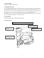
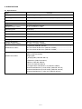
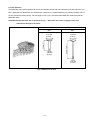
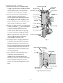
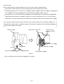
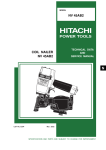
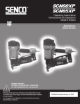
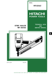
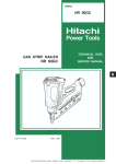
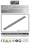
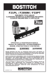
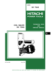
MODEL
NV 45AC
POWER TOOLS
COIL NAILER
NV 45AC
TECHNICAL DATA
AND
SERVICE MANUAL
N
LIST No. 1098
Nov. 2000
SPECIFICATIONS AND PARTS ARE SUBJECT TO CHANGE FOR IMPROVEMENT
CONTENTS
Page
1. PRODUCT NAME .............................................................................................................................. 1
2. MARKETING OBJECTIVE ................................................................................................................ 1
3. APPLICATIONS ................................................................................................................................. 1
4. SELLING POINTS ............................................................................................................................. 1
5. SPECIFICATIONS ............................................................................................................................. 2
5-1. Specifications ......................................................................................................................................2
5-2. Nail Selection ......................................................................................................................................3
5-3. Nail Driving Force ...............................................................................................................................4
5-4. Optional Accessories ..........................................................................................................................5
6. COMPARISONS WITH SIMILAR PRODUCTS ................................................................................. 6
7. PRECAUTIONS IN SALES PROMOTION ........................................................................................ 7
7-1. Instruction Manual ..............................................................................................................................7
7-2. Warning Label .....................................................................................................................................7
7-3. Related Laws and Regulations ...........................................................................................................8
8. MECHANISM AND OPERATION PRINCIPLE .................................................................................. 8
8-1. Mechanism .........................................................................................................................................8
8-2. Operation Principle ...........................................................................................................................10
9. TROUBLESHOOTING GUIDE ........................................................................................................ 12
9-1. Troubleshooting and Correction ........................................................................................................12
9-2. Possible Causes and Corrections of Air Leakage .............................................................................17
10. DISASSEMBLY AND REASSEMBLY ........................................................................................... 19
10-1. General Precautions in Disassembly and Reassembly .................................................................. 19
10-2. Disassembly and Reassembly of the Output Section ..................................................................... 20
10-3. Disassembly and Reassembly of the Control Valve Section ..........................................................22
10-4. Disassembly and Reassembly of the Driving Section .................................................................... 25
10-5. Disassembly and Reassembly of the Cap and the Magazine Section ........................................... 29
11. INSPECTION AND CONFIRMATION AFTER REASSEMBLY ..................................................... 32
12. STANDARD REPAIR TIME (UNIT) SCHEDULES ........................................................................ 33
[ Appendix]
Assembly Diagram for NV 45AC .............................................................................................................34
1. PRODUCT NAME
Hitachi 1-3/4" Coil Nailer, Model NV 45AC
2. MARKETING OBJECTIVE
The current Model NV 45AB coil nailer is well-reputed in the U.S.A. market as a roofing nailer suitable for roofing
asphalt shingles in building construction. However, competitively priced roofing nailers have been put on the
U.S.A. market recently. The newly developed Model NV 45AC is specifically designed for roofing asphalt shingles
and weighs just 1.7 kg (3.7 lbs.). Please expand our market share with the new Model NV 45AC.
The Model NV 45AC is a medium-duty roofing coil nailer capable of asphalt shingles with 25 --- 45 mm length nails
after heavy-duty Model NV 45AB for 22 --- 45 mm length nails.
3. APPLICATIONS
Installation of asphalt roofing shingles in building construction
4. SELLING POINTS
Lightweight 1.7 kg (3.7 lbs.) for easy one-handed operation
Rubber protector protects
tool and prevents sliding
Exhaust direction easily
changeable
Rubber grip for comfort and
temperature protection
Nailing depth adjustment
mechanism with an easyto-see calibrated dial
--- 1 ---
5. SPECIFICATIONS
5-1. Specifications
NV 45AC
Model
Driving system
Reciprocating piston type
Operating pressure
4.9 --- 8.3 bar (5 --- 8.5 kgf/cm2, 70 --- 120 psi) (Gauge pressure)
Driving speed
3 nails/sec.
Weight
1.7 kg (3.7 lbs.)
Dimensions
(Length x Height x Width)
241 mm x 269 mm x 124 mm
(9-1/2" x 10-19/32" x 4-7/8")
Nail feed system
Spiral spring
Nail capacity
120 nails (1 coil)
Air consumption
1.0 ltr/cycle at 6.9 bar (1.0 ltr/cycle at 7 kgf/cm2) (0.035 ft3/cycle at 100 psi)
Air inlet
3/8 NPT thread
Packaging
Corrugated cardboard box
Package dimensions
(Length x Height x Width)
280 mm x 290 mm x 150 mm
(11-1/32" x 11-13/32" x 5-29/32")
Standard accessories
Eye protector (Code No. 875769) .............................................................. 1
Hex. bar wrench for M6 screw (Code No. 944459) .................................... 1
Hex. bar wrench for M5 screw (Code No. 944458) .................................... 1
Optional accessories
Sequential trip mechanism kit (Single-shot) (Code No. 881973)
Muffler (Code No. 881835)
Shingle guide
Shingle guide (Code No. 878175)
Guide base (Code No. 878176)
Washer (Code No. 949424)
Plate nut (Code No. 878213)
Hexagon socket hd. bolt M5 x 16 (Code No. 949819)
Pneumatic tool lubricant (1 oz oil feeder) (Code No. 877153)
Pneumatic tool lubricant (4 oz oil feeder) (Code No. 872042)
Pneumatic tool lubricant (1 quart can) (Code No. 876212)
--- 2 ---
5-2. Nail Selection
The Model NV 45AC utilizes roofing nails which are common round-head nails collated by wire into coils from 120
nails. Applicable nail dimensions are shown below. However, it is recommended to use genuine HITACHI nails to
ensure satisfactory driving quality. For nail length 22 mm (7/8"), recommend the Model NV 45AB instead of this
Model NV 45AC.
CAUTION: Ensure that nails are as specified in Fig. 1. Other nails will cause clogging of nails and
subsequent damage to the nailer.
Wire-collated nails
10.5 mm
(0.413")
10.5 mm
(0.413")
3.05 mm
(0.120")
45 mm (1-3/4")
Max.
25 mm (1")
Min.
3.05 mm
(0.120")
Fig. 1 Dimensions of nails
--- 3 ---
5-3. Nail Driving Force
Fig. 2 shows by type of wood and nail the nailer output energy provided by the supply pressure and the nailing
energy required for driving the nail flush. Air pressure which exceeds the intersecting point between the nailer
output energy and the required nailing energy for driving the nail allows the nail to be fully driven.
For example, when driving a nail of 3.05 mm dia. x 45 mm length (0.120" x 1-3/4") into a workpiece of hemlock
with the Model NV 45AC, a pressure of about 6.9 bar (7 kgf/cm2, 100 psi) allows the nailer to drive the nail flush
with the wood surface. A pressure beyond this value causes the nail head to be driven below the wood surface.
Fig. 2 should be used as a reference only because those values vary depending on the type of wood, moisture
content, and grain of wood.
Max CN450R
Bostitch N63CP
Porter Cable RN175
Senco SCN40R
Hitachi NV 45AB
Hemlock
NV 45AC
Fig. 2 Required nailing energy and nailer output energy
--- 4 ---
5-4. Optional Accessories
(1) Sequential trip mechanism kit
The sequential trip mechanism kit is provided as an optional accessory for the Model NV 45AC. When using
this optional accessory, a nail is driven by pressing the push lever first against a workpiece and then pulling
the trigger, and no nail is driven when pulling the trigger first and then pressing the push lever against a
workpiece (single-shot operation). Please recommend the sequential trip mechanism kit to customers who
may want to use it. Salespersons must instruct the customers to read thoroughly the Instruction Manual
attached to the sequential trip mechanism kit and also the Handling Instructions of the Model NV 45AC for
correct use.
(2) Muffler
The muffler is provided as an optional accessory for the Model NV 45AC. By mounting this muffler, the
exhaust sound is reduced by about 10 dB (A). Please recommend the muffler to customers who may want to
use it. The muffler can be mounted according to the following procedure as shown in Fig. 3.
1. Remove the hex. socket hd. bolt M5 x 10.
2. Put the muffler in the head ring with the convex side facing the top cover.
3. Fit the convex portion of the exhaust cover in the concave portion of the top cover.
4. Secure it with the hex. socket hd. bolt M5 x 10.
Hex. socket hd. bolt
M5 x 10
Washer
Top cover
Concave portion of top cover
Convex portion of muffler
Muffler
Convex portion of exhaust cover
Exhaust cover
Head ring
Fig. 3 Mounting of muffer
--- 5 ---
--- 6 ---
NV 45AB
2.5 kg (5.5 lbs.)
2.7 kg (6.0 lbs.)
4.9 --- 6.9 bar
(5 --- 7 kgf/cm2)
(70 -- 100 psi)
RN45B
BOSTITCH
2.4 kg (5.3 lbs.)
4.9 -- 8.3 bar
(5 -- 8.5 kgf/cm2)
(70 -- 120 psi)
SCN40R
SENCO
Provided
Replaceable anti-slip
protector
Applicable
nails
Handle grip
None
19 mm --- 38 mm
(3/4" --- 1-1/2")
22 mm -- 45 mm
(7/8" -- 1-3/4")
19 mm -- 45 mm
(3/4" -- 1-3/4")
25 mm -- 45 mm
(1" -- 1-3/4")
3.05 mm (0.120")
3.05 mm (0.120")
3.05 mm (0.120")
Shank dia.
Length
10 mm (0.394")
10.5 mm (0.413")
10.5 mm (0.413")
Wire
Wire
Head dia.
Foam rubber
(Apt to peel off)
3.05 mm (0.120")
19 mm -- 45 mm
(3/4" -- 1-3/4")
22 mm -- 45 mm
(7/8" -- 1-3/4")
10.5 mm (0.413")
Wire
Rubber
(Not elastic)
Provided
3.05 mm (0.120")
9.8 mm (0.385")
Wire
Rubber
(Not elastic)
None
Provided
None
None
Provided
None
Tool not required
None
Top loading
(Plastic)
120 nails
2.0 ltr/cycle
(0.070 ft3/cycle)
275 mm x 268 mm x 111 mm
(10-13/16" x 10-9/16" x 4-3/8")
2.5 kg (5.5 lbs.)
4.5 -- 6.9 bar
(4.6 -- 7 kgf/cm2)
(65 -- 100 psi)
CN450R
MAX
Provided
Tool not required
Tool not required
Top loading
(Plastic)
120 nails
1.4 ltr/cycle
(0.049 ft3/cycle)
300 mm x 257 mm x 110 mm
(11-13/16" x 10-1/8" x 4-11/32")
2.3 kg (5.1 lbs.)
4.9 -- 8.3 bar
(5 -- 8.5 kgf/cm2)
(70 -- 120 psi)
RN175
PORTER CABLE
Provided
Tool not required
None
Rubber
(Not elastic)
None
None
Provided
None
Tool required
Wire
Racket grip
(Comfortable grip)
None
None
Tool not required
None
Collation
Exhaust muffler
Optional
Tool not required
Driving depth
adjustment mechanism
Trigger lock mechanism
Tool not required
Direction change of
exhaust air
Top loading
(Plastic)
Top loading
(Plastic)
Bottom loading
(Plastic)
Magazine type
(Material)
1.3 ltr/cycle
(0.046 ft3/cycle)
120 nails
1.8 ltr/cycle
(0.064 ft3/cycle)
120 nails
1.2 ltr/cycle
(0.042 ft3/cycle)
120 nails
1.0 ltr/cycle
(0.035 ft3/cycle)
248 mm x 264 mm x 117 mm
241 mm x 269 mm x 124 mm 250 mm x 264 mm x 124 mm
277 mm x 269 mm x 117 mm
(9-1/2" x 10-19/32" x 4-7/8") (9-27/32" x 10-13/32" x 4-7/8") (10-29/32" x 10-19/32" x 4-19/32") (9-3/4" x 10-13/32" x 4-19/32")
1.7 kg (3.7 lbs.)
4.9 --- 8.3 bar
(5 --- 8.5 kgf/cm2)
(70 --- 120 psi)
NV 45AC
HITACHI
Nail capacity
Air consumption at 6.9
bar (7 kgf/cm2, 100 psi)
Dimensions
(L x H x W)
Weight
Operating pressure
Model name
Maker
6. COMPARISONS WITH SIMILAR PRODUCTS
7. PRECAUTIONS IN SALES PROMOTION
In the interest of promoting the safest and most efficient use of the Model NV 45 AC Nailer by all of our customers,
it is very important that at the time of sale the salesperson carefully ensures that the buyer seriously recognizes
the importance of the contents of the Instruction Manual, and fully understands the meaning of the precautions
listed on the Warning Label attached to each tool.
7-1. Instruction Manual
Although every effort is made in each step of the design, manufacture, and inspection to provide protection
against safety hazards, the dangers inherent in the use of any pneumatic tool cannot be completely eliminated.
Accordingly, general precautions and suggestions for use of pneumatic tools, and specific precautions and
suggestions for the use of the pneumatic nailer are listed in the Instruction Manual to enhance the safe, efficient
use of the tool by the customer.
Salespersons must be thoroughly familiar with the contents of the Instruction Manual to be able to offer
appropriate guidance to the customers during sales promotion.
7-2. Warning Label
Each Model NV 45AC unit is provided with a Warning Label (illustrated below) which lists basic safety precautions
in its use. Carefully ensure that customers fully understand and follow these precautions before using the tool.
--- 7 ---
7-3. Related Laws and Regulations
As nailers and staplers are designed to instantaneously drive nails and staples, there is an ever-present danger of
misfiring and subsequent possible serious injury. Accordingly, close attention in handling is absolutely necessary
at all times. Carefully ensure that the customer is fully aware of the precautions listed in the Instruction Manual
provided with each unit.
While there are no specific safety regulations, there are related items in various general safety regulations with
which the salespersons should be familiar in order to properly advise the customer. Please check your national
and/or local regulations for applicable items. Some applicable items are outlined below.
The U.S.A:
OSHA
1926.102 Eye and face protection
1926.302 Power-operated hand tools
ANSI SNT-101-1993
Portable, Compressed-Air-Actuated,
Fastener Driving Tools-Safety Requirements for
8. MECHANISM AND OPERATION PRINCIPLE
8-1. Mechanism
As illustrated in Fig. 4, NV 45AC can be generally divided into four sections: output section, control valve section,
driving section and magazine section. Most of the parts of the above sections have been newly designed, though
its basic construction is the same as that of the Model NV 50AG. Primary differences from the Model NV 50AG
are described below.
Output section ................... Most of the parts have been newly designed, though its basic construction is the
same as that of the Model NV 50AG. The piston unit employs O-rings at the
sliding portion in the same manner as the Model NV 45AB instead of a piston
ring. The protector has been newly designed to prevent slipping of tool.
Control valve section .......... This section is common to the Models NR 90AC and NV 65AH.
Driving section .................... The adjuster has been newly designed to improve operability in nailing depth
adjustment.
The plastic guard shielding the pushing lever and the feed piston has been newly
designed to prevent adhesion of dust.
Magazine section ................ This section is common to the Model NV 45AB, though the shingle guide is not
provided. The shingle guide is interchangeable between the Model NV 45AB and
the Model NV 45AC.
--- 8 ---
Valve Piston (B) [59]
Plunger Spring [61]
Valve Bushing (B) [55]
Protector [5]
Top Cover [3]
Exhaust Vent
Plunger (A) [62]
Valve Bushing (A) [64]
Head Ring [4]
Output section
Head Valve (A) [12]
Exhaust
Cover [8]
Control valve
section
Body Ass'y [21]
Cap [49]
Accumulator
Piston [14]
(Drive Blade)
Magazine [95]
Cylinder [19]
Trigger (A) [25]
Piston
Bumper [20]
Adjuster [71]
Driving section
Nose [36]
Guard [32]
Magazine
Stopper [93]
Feeder [41]
Pushing
Lever (A) [42]
Magazine Cover [102]
Nail Holder [99]
Magazine section
Guide Lock [81]
Nail Stopper (A) [84]
Nail Guide [83]
Nail Stopper (B) [86]
Feeder [41]
Fig. 4 Construction
--- 9 ---
Feed Piston [73]
8-2. Operation Principle
(1) Before nailing: (Fig. 5 and Fig. 6)
Exhaust Cover [8]
1) When compressed air is fed to the main body,
it fills the accumulator (
Head valve
chamber
Exhaust vent
).
2) At the same time, the compressed air flows into
the valve piston lower chamber of the control
Head Valve
Spring [10]
Air passage
Head Valve (A) [12]
Control valve
section
valve section and forces Valve Piston (B) [59]
Piston [14]
upward. Also, the compressed air is fed through
Accumulator
the air supply vent and air passage to the head
valve chamber. As a result, the Head Valve Spring
Cylinder hole
Cylinder [19]
[10] is pushed down together to seal Head
Valve (A) [12] and Cylinder [19].
Return air
chamber
(2) When nailing: (Fig. 5 and Fig. 6)
Trigger (A) [25]
1) When Pushing Lever (A) [42] and Trigger (A) [25]
are operated together and Plunger (A) [62] is
Pushing Lever (A) [42]
pushed upward, the compressed air in the valve
piston lower chamber is discharged from the
Nail
bottom of Plunger (A) [62]. As a result, the
compressed air in the accumulator (
) pushes
Fig. 5
down Valve Piston (B) [59], blocking the air
supply vent and opening the exhaust valve.
2) When the exhaust valve opens, the compressed
air in the head valve chamber is discharged into
To the head valve chamber
the atmosphere through the air passage.
3) When the air pressure applied on the bottom
Air
passage
surface of Head Valve (A) [12] overcomes the
Air supply vent
Accumulator
strength of the Head Valve Spring [10], Head
Valve (A) [12] is pushed upward. At this time,
Exhaust
valve
Head Valve (A) [12] seals the Exhaust Cover [8],
blocking the passage to the exhaust vent.
4) When Head Valve (A) [12] goes up, the
compressed air in the accumulator flows rapidly
into the Cylinder [19], forcing the Piston [14]
Valve Piston (B) [59]
downward to strike the nail. When the Piston
Valve piston
lower chamber
[14] passes the cylinder hole, the compressed air
Plunger (A) [62]
flows into the return air chamber and is
Fig. 6 Control valve section
accumulated there.
--- 10 ---
(3) During return: (Fig. 7 and Fig. 8)
1) When either Pushing Lever (A) [42] or Trigger
Exhaust Cover [8]
(A) [25] is released, Plunger (A) [62] goes down
and the compressed air in the accumulator
Head valve
chamber
Exhaust vent
Head Valve (A) [12]
Air passage
flows into the valve piston lower chamber.
2) As the air pressure in the valve piston lower
Control valve
section
Accumulator
chamber increases to overcome the air
Cylinder [19]
pressure applied on the upper portion of Valve
Return air
chamber
Piston (B) [59], Valve Piston (B) [59] is forced
upward. When this occurs, the exhaust valve is
closed and the air supply vent is opened.
Piston [14]
3) When the air supply vent opens, the compressed
air in the accumulator (
) passes through the
Piston
Bumper [20]
Trigger (A) [25]
air passage and flows into the head valve
Driver blade
chamber to push down Head Valve (A) [12].
As a result, Head Valve (A) [12] and Cylinder
[19] are sealed and, at the same time, Head
Nail
Pushing Lever (A) [42]
Valve (A) [12] and Exhaust Cover [8] are
released to open the exhaust vent.
4) The compressed air at the upper portion of the
Fig. 7
Piston [14] is discharged into the atmosphere
through the exhaust vent. In this way, the air
pressure at the upper portion of the Piston [14]
is reduced, and the greater pressure of the air
To the head valve chamber
accumulated in the return air chamber pushes
Air supply
vent
the Piston [14] upward.
Air
passage
5) If the air pressure at the lower portion of the
Accumulator
Piston [14] is higher than that of the
atmosphere after the Piston [14] has fully
returned, the excess air pressure is discharged
into the atmosphere through the clearance
between the Piston Bumper [20] and the driver
blade.
Exhaust valve
Valve Piston (B) [59]
Valve piston
lower chamber
Plunger (A) [62]
Fig. 8 Control valve section
--- 11 ---
9. TROUBLESHOOTING GUIDE
9-1. Troubleshooting and Correction
Problem
1) Nails cannot
be driven.
(
Possible cause
: most-common cause)
Inspection methods
Remedy
<Nails>
Magazine is not loaded with
specified genuine nails.
Magazine is loaded with
abnormal nails (bent nails,
too large or too small nail
heads, abnormal collation,
others).
Nails or link pieces are
jammed.
Link pieces are deformed or
broken.
Check that the magazine is
correctly loaded with
specified nails.
Use specified nails.
Remove the abnormal nails
and load the nailer with
proper nails.
<Driving section: Nose, feeder,
Remove the feed piston
and check the feed piston
sliding surface of the
nose.
Apply grease to the sliding
surface.
Polish the scratched portion
with sandpaper. Replace
the parts.
Nail guide face of the nose
is abnormal (deformed,
burrs or damaged).
Spring or feeder spring is
abnormal (damaged or
fatigued).
Feeder is abnormal
(damaged or worn).
Check that the driving
section is not abnormal
(burrs, deformed, damaged
or worn).
Deburr the nail guide face.
Correct the deformed part.
Replace the abnormal parts.
Nails are not correctly
loaded in the groove of the
nose.
Check that nails are
correctly loaded in the
groove of the nose.
Load nails in the correct
position in the nose.
Dust sticks to the feeder
sliding portion of the nose,
or lubrication is needed.
Open the nail guide and
perform idle driving to check
the feeder's operation.
Remove dust and then
lubricate the sliding surface.
feed piston, etc.>
Sliding resistance of the
feed piston is too high.
Adjust the air pressure to
4.9 --- 8.3 bar (5 --- 8.5 kgf/cm2,
70 --- 120 psi).
Air pressure is too low.
Remove foreign matter.
Replace the piston bumper
with new one.
Body ... Remove foreign
matter in the return
air chamber.
Nose ... Remove foreign
matter in the air
passage and the
feed piston
chamber.
Air passage is clogged
with broken pieces of
piston bumper, etc.
Feeder piston chamber
contains foreign matter
such as broken pieces of
piston bumper, etc.
--- 12 ---
Problem
1) Nails cannot
be driven.
(
Possible cause
: most-common cause)
Inspection methods
Remedy
Air leaks from the gap
between the body and the
nose.
Tighten screws and check
the O-rings.
O-rings are worn or
deformed.
Replace the O-rings.
O-rings need lubrication.
Apply grease or lubricate.
<Nail guide section>
Nail guide face is abnormal
(deformed, burrs or
damaged).
Dust stickes to the inside of
the nail guide groove, or
lubrication is needed.
Check that the nail guide is
not abnormal (worn,
deformed, damaged, etc.).
Correct or replace the parts.
Check the operation of nail
stopper (A) and nail stopper
(B).
Remove dust and then
lubricate.
Replace the abnormal parts.
Spring is abnormal (missing,
damaged or fatigued).
The claw ridge section of the
nail stopper is abnormal
(damaged, worn or burrs).
<Magazine section>
<Pushing lever>
Magazine
Check that a nail does not
catch on another nail in the
magazine.
Check that a nail does not
catch on some part of the
magazine.
Check the height of the nail
holder.
Collate the nails correctly
and reload the nailer with
them.
Remove burrs or deformed
part. Replace the parts.
Adjust the height of the nail
holder correctly.
Pushing lever
Check the operation of the
pushing lever.
Correct or replace the parts.
Open the nail guide and
perform idle driving to check
that the driver blade is
returned.
Adjust the air pressure to
4.9 -- 8.3 bar (5 -- 8.5 kgfcm2,
70 -- 120 psi).
<Output section:piston, driver
blade, etc.>
Air pressure is too low.
O-ring in the piston is
abnormal
(worn or damaged).
Replace the O-ring.
Piston bumper is abnormal.
Replace the piston bumper.
O-ring in the cylinder is
abnormal (removed, deformed
or damaged).
Reassemble or replace the
parts.
Driver blade is abnormal
(deformed, burrs or damaged).
Correct or replace the part.
--- 13 ---
Problem
1) Nails cannot
be driven.
(continued)
Possible cause
: most-common cause)
Inspection methods
Cylinder inside surface is
abnormal (packed with dust,
or worn).
Check that nails can be
driven at 4.9 bar (5 kgf/cm2,
70 psi).
Remove dust and then
lubricate.
Replace the part.
Head valve sliding surface is
abnormal (seized or
damaged, or lubrication is
needed).
Perform idle driving to check
the driving operation.
Replace the part.
Apply grease.
Head valve spring is
abnormal (fatigued or
damaged).
Perform idle driving to check
that the driver blade is not
held in the down position.
Replace the part.
(
Replace the abnormal part.
<Control valve section>
Plunger (A), valve piston (B),
valve bushing (A) or valve
bushing (B) is abnormal
(seized or damaged).
Disassemble the control
valve section and check
the O-rings.
Replace the abnormal part.
Apply grease.
Check that the adjuster is
not raised too high.
Turn the adjuster lower
(lower the pressure).
See item 1).
See item 1).
Driver blade is worn.
Check that the driver blade
tip is not abnormally worn.
Replace the part.
Workpiece is too hard.
Check if a nail is bent even
when driven into soft wood.
Nailer cannot be used
because the material is
beyond its applicable range.
Adjuster is incorrectly set.
Turn the adjuster to the
lowest position and then
drive nails.
Set the adjuster to the
optimum position.
O-ring or sliding surface is
worn or needs lubrication.
2) Nails are
driven but
bent.
Adjuster is raised too high
for short nails.
Nails are not completely fed
into the injection port.
Unspecified nails are used.
3) Nails cannot
be driven into
the workpiece
completely:
the heads
cannot be
made flush.
Remedy
Adjust air pressure to
4.9 --- 8.3 bar
(5 --- 8.5 kgf/cm2, 70 ---120 psi).
Air pressure is too low.
Workpiece is too hard.
Check if a nail is bent even
when driven into soft wood.
--- 14 ---
Nailer cannot be used
because the material is
beyond its applicable range.
4) Nails jam.
Possible cause
: most-common cause)
Inspection methods
Remedy
Perform idle driving to check
the driver blade is projected
from the nose tip.
Replace the part.
O-ring in the piston is
abnormal (worn or
damaged).
Cylinder inside surface is
abnormal (worn or rough).
Disassemble the output
section and check the
O-ring and the inside of the
cylinder for abnormality.
Replace the abnormal part.
Cylinder plate or O-ring is
abnormal (removed,
deformed or damaged).
Disassemble the cylinder
plate and check for
abnormality.
Replace the abnormal part.
Head valve sliding surface is
abnormal (seized or
damaged, or lubrication is
needed).
Check the sliding surface for
abnormality and lubrication.
Replace the abnormal part.
Apply grease.
Check if the specified nails
are used.
Check the nails as follows.
Use specified nails.
Remove the abnormal nails
and load the nailer with
proper nails.
Driver blade is worn.
<Nails>
Unspecified nails are used.
Abnormal nails are mixed.
Nail heads are too large or
too small.
Collating wires are abnormal
(broken, welding failed,
deformed or welding position
failed).
Collating wires are
deformed (deformed in
collation angle or collation
pitch).
10.5
(0.41
3)
L2
3) Nails cannot
be driven into
the workpiece
completely:
the heads
cannot be
made flush.
(continued)
(
8
(0.31
5)
UNIT: mm (inch)
L1
Problem
16˚
30.5
(0.12
0)
--- 15 ---
Type
A
L1
7
(0.276)
L2
16
(0.630)
B
7
(0.630)
25
(0.984)
Problem
4) Nails jam.
(continued)
(
Possible cause
: most-common cause)
Inspection methods
Remedy
<Body: Nail feeding is
incomplete.>
Feeder is worn and the
sliding section is abnormal.
Nail guide face of the nose
or the sliding section of the
feeder is abnormal
(deformed, burrs or
damaged).
Spring or feeder spring is
abnormal (damaged,
fatigued or removed).
Open the nail guide and
check the position of the
feeder claw. Check that the
feeder claw holds a nail, and
the first nail is positioned in
the injection port. (Check
that the second claw holds
the nail shaft and feeds it.)
Replace the abnormal part.
<Body: Nail guide section>
Nail guide section is
abnormal.
See item "1) Nail guide
section".
See item "1) Nail guide
section".
<Driver blade is not returned
completely.>
See item "1) Output section:
piston, driver blade, etc.".
Perform idle or actual
driving to check if the driver
blade is returned
completely.
See item "1) Output section:
piston, driver blade, etc.".
Nails may be jammed if
driven at a high pressure
and high speed. Check
pressure and driving speed.
Adjust the air pressure to
4.9 --- 8.3 bar (5 -- 8.5 kgf/cm2,
70 --120 psi).
Air pressure is too high.
--- 16 ---
9-2. Possible Causes and Corrections of Air Leakage
Air leakage repair location
Repair procedure
a
(1) Check the points of the
(A)
following parts marked
b
by an asterisk for
c
d
(B)
abnormal condition.
(H)
(2) Next, check the seal
parts (marked with a
double circle) for wear,
flaws or damage.
(3) And then, check other
e
places.
(C)
Nail feeder section
Control valve section
f
g
(C)
h
(E)
(E)
(F)
(G)
(D)
Air leakage points
Possible cause
With control valve OFF
(A) Exhaust port
Head Valve (A) [12] and Cylinder [19]
are abnormal (seal surface of the (b)
portion is worn or deformed).
The Head Valve O-ring [11] is abnormal
(worn, deformed or damaged).
Head Valve (A) [12] is abnormal (worn,
deformed or damaged).
(B) Exhaust cover
The Hex. Socket Hd. Bolt M5 x 22 [6]
is loose.
Gasket (A) [9] is damaged.
The seal surface of the Body Ass'y [21]
or the Exhaust Cover [8] is abnormal.
--- 17 ---
With control valve ON
Head Valve (A) [12] is abnormal ((a)
portion is worn, deformed or broken).
The Exhaust Cover [8] is abnormal ((a)
portion is deformed or clogged with
dust).
Air leakage points
Possible cause
With control valve OFF
(C) Nose (I)
(D) Nose (II)
With control valve ON
The O-Rings [24] [31] of the Body Ass'y
[21] are abnormal (broken or
damaged).
The Nylock Bolt (W/Flange) M6 x 25
[35] is loose.
The seal surface of the Body Ass'y [21]
or the Nose [36] is abnormal (broken,
deformed or scratched).
The Cylinder O-Ring (1AS-50) [15] of
the Cylinder Plate [16] is abnormal
(broken or damaged).
The O-Ring (S-36) [17] of the Cylinder
[19] is abnormal (broken or damaged).
The seal surface of the Body Ass'y [21],
Cylinder Plate [16] or Cylinder [19] is
abnormal ( c or d portion).
The Piston Bumper [20] is abnormal
( e or f portion is damaged,
deformed or cracked).
The Piston [14] is abnormal (driver
blade or sealed face is deformed).
The f surface of the Body Ass'y [21]
is deformed.
The O-Ring (P-18) [74] on the Feed
Piston [73] is abnormal (worn, broken
or damaged) or the Nose [36] is worn,
deformed or scratched on the sliding
surface.
The O-Ring (P-9) [72] in the Nose [36]
is abnormal (worn, broken or damaged)
or the Feed Piston [73] is worn,
deformed or scratched on the sliding
surface.
(E) Feed piston
(F) Control valve (I)
The O-Ring [60] on Valve Piston (B)
[59] is abnormal (worn, broken or
damaged).
The lower O-Ring [57] on Valve Piston
(B) [59] is abnormal (worn, broken or
damaged).
The O-Ring (S-18) [56] on Valve
Bushing (B) [55] is abnormal (broken or
damaged).
The inside surface of the valve chamber
of the Body Ass'y [21] is abnormal.
The upper O-Ring [57] on Valve Piston
(B) [59] is abnormal (worn, broken or
damaged).
The Head Valve O-Ring [11] on Valve
Bushing (B) [55] is abnormal (broken or
damaged).
The top surface of the valve chamber of
the Body Ass'y [21] is abnormal ( g
portion).
(G) Control valve (II)
The O-Ring [63] on Plunger (A) [62] is
abnormal (worn, broken or damaged).
Valve Bushing (A) [64] is abnormal
(sliding surface of Plunger (A) [62] is
deformed or scratched).
The inside of the O-Ring (S-4) [58] on
Valve Piston (B) [59] is abnormal (worn,
broken or damaged).
Plunger (A) [62] is abnormal (sliding
surface is deformed or scratched).
(H) Cap
The O-Ring [48] is abnormal (worn, broken or damaged).
The Cap [49] is loose.
The seal surface of the Body Ass'y [21] or the Cap [49] is abnormal (broken,
deformed or scratched).
--- 18 ---
10. DISASSEMBLY AND REASSEMBLY
The items particularly necessary for disassembly and reassembly are described below. The [Bold] numbers in
the descriptions below correspond to the item numbers in the Parts List and exploded assembly diagram.
[CAUTION]
Before disassembly or reassembly, be sure to disconnect the air hose from the nailer (with your finger
released from the trigger) to exhaust all the compressed air and remove all nails.
10-1. General Precautions in Disassembly and Reassembly
Apply grease (Nippeco SEP-3A, Code No. 930035) to the O-rings and O-rings' sliding portions. When
installing the O-rings, be careful not to damage the O-rings and prevent dirt entry.
Oil required: Hitachi pneumatic tool lubricant
1 oz (30 cc) Oil feeder (Code No. 877153)
4 oz (120 cc) Oil feeder (Code No. 874042)
1 quart (1 ltr) Can (Code No. 876212)
If Gasket (A) [9] is damaged, replace it and check that no air is leaking.
Be especially careful to prevent the entry of foreign particles into the control valve section.
Tightening torque for each part
Tightening torque
N•m (kgf•cm, ft-lbs)
Bolt, screw and cap
Nylock Bolt (W/Flange) M6 ........................................... [35]
14.7
Nylock Hex. Socket Hd. Bolt M5 ................................... [88]
8.3
0.5 (85
5, 6.1
0.4)
Hex. Socket Hd. Bolt M5 ............................................... [43]
8.3
0.5 (85
5, 6.1
0.4)
Hex. Socket Hd. Bolt M5 ............................................... [1][6]
6.3
0.5 (65
5, 4.7
0.4)
Hex. Socket Hd. Bolt M5 ............................................... [100]
2.0
0.3 (20
3, 1.5
0.2)
Machine Screw (W/Sp. Washer) M5 ............................. [44]
2.0
0.5 (20
5, 1.5
0.4)
Machine Screw M4 ....................................................... [96]
0.5 --- 1.0 (5 --- 10, 0.36 --- 0.72)
Cap................................................................................ [49]
24.5
--- 19 ---
0.8 (150
8, 10.8
4.9 (250
50, 18
0.6)
3.6)
10-2. Disassembly and Reassembly of the Output Section (See Fig. 9)
Hex. Socket Hd.
Bolt M5 x 10 [1]
[Tool required]
Washer [2]
(a) Disassembly
Hex. bar wrench (4 mm)
Remove the Hex. Socket Hd. Bolts M5 x 10
Top Cover [3]
[1] with a hex. bar wrench (4 mm). Then
Head Ring [4]
the Top Cover [3], the Head Ring [4], and
the Protector [5] can be removed.
Protector [5]
Hex. Socket Hd.
Bolt M5 x 22 [6]
Remove the four Hex. Socket Hd. Bolts
M5 x 22 [6] with a hex. bar wrench (4 mm)
and remove the Exhaust Cover [8]. Then
Body Guard [7]
the components of the output section such
Exhaust Cover [8]
Gasket (A) [9]
as the Piston [14], Cylinder [19] and the
6 mm (0.236")
Hole
Piston Bumper [20] can be removed.
(b) Reassembly
Head Value Spring
[10]
Head Value O-Ring
(I.D 16.8) [11]
Disassembly procedures should be
followed in the reverse order. Note the
following points:
Head Value (A) [12]
Apply grease to the inside of the O-ring
(1BP-28) [13], O-ring (S-36) [17], O-ring
O-Ring (1BP-28) [13]
(1AS-15) [15] and the Cylinder [19] before
Piston [14]
reassembly.
Mount the Cylinder Plate [16] aligning the
O-Ring (S-50) [15]
triangle mark with the mark on the Body
Ass'y [21] as shown in Fig. 10.
Cylinder Plate [16]
Mount the Gasket (A) [9] aligning the 6 mm
(0.236") dia. hole with the blowhole of the
O-Ring (S-36) [17]
Body Ass'y [21].
Cylinder O-Ring [18]
Triangle mark on the
Cylinder Plate [16]
Cylinder [19]
Mark on the
Body Ass'y [21]
Blowhole
Piston Bumper [20]
Body Ass'y [21]
Cylinder Plate [16]
Fig. 9 Disassembly and reassembly of the output section
--- 20 ---
Body Ass'y [21]
Fig. 10
Head Valve O-Ring
(I.D 16.8) [11]
Top Cover [3]
Groove of the
Exhaust Cover [8]
Concave portion of
the Top Cover [3]
Apply grease to the sliding surface (A) of
the Exhaust Cover [8] and Head Valve (A)
[12] and charge about 0.5 g (0.018 oz) of
grease in the groove of the Exhaust Cover
[8] (Fig. 11).
Apply grease to the lip portions (B) and
(C) of Head Valve (A) [12] (Fig. 11).
Convex portion
of the Exhaust
Cover [8]
Apply grease to the Head Valve O-Ring
(I.D 16.8) [11]. Mount the Head Valve
O-Ring (I.D 16.8) [11] to Head Valve (A)
[12], then mount it to the Exhaust Cover
[8].
Head Valve (A) [12]
A
C
B
Fit the convex portion of the Exhaust
Exhaust Cover [8]
Fig. 11
Cover [8] in the concave portion of the
Top Cover [3] (Fig. 11).
--- 21 ---
10-3. Disassembly and Reassembly of the Control Valve Section (See Fig. 12)
[Tools required]
Retaining Ring (E-Type)
for D6 Shaft [22]
Flatblade head screwdriver
Roll Pin
D3 x 18 [52]
Body Ass'y [21]
Roll pin puller (3 mm (0.118 ") dia.)
Hex. bar wrench (4 mm)
Trigger (A) [25]
Trigger Pin [54]
Head Valve O-Ring
(I.D 16.8) [11]
(a) Disassembly
Valve Bushing (B) [55]
Remove the Retaining Ring (E-Type) for D6
O-Ring (S-18) [56]
Shaft [22] with the blade of a screwdriver and
O-Ring (I.D 8.8) [57]
remove the Trigger Pin [54], and Trigger (A) [25]
O-Ring (S-4) [58]
can be removed.
Valve Piston (B) [59]
O-Ring (I.D 11) [60]
To remove Trigger (A) [25] together with the
driving section (Pushing Lever (B) [70], the Nose
Plunger Spring [61]
[36], etc.), remove Trigger (A) [25] while forcing
Plunger (A) [62]
down Plunger (A) [62] with the blade of a
O-Ring (I.D 1.8) [63]
screwdriver, as shown in Fig. 13.
Valve Bushing (A) [64]
Remove
Pushing Lever (B) [70]
Trigger (A) [25]
Force down
Plunger (A) [62]
Screwdriver
Fig. 13
--- 22 ---
Pull out the Roll Pin D3 x 18 [52] with the roll pin
puller (3 mm (0.118") dia.), and take out the
Push
control valve in the following manner.
Body Ass'y [21]
4 to 5 mm (0.157" to 0.197")
dia. bar
1) Remove the Exhaust Cover [8] by following
the procedure in (1), section 10-2.
Head Valve O-Ring
(I.D 16.8) [11]
2) As shown in Fig. 14, put a 4 to 5 mm (0.157 to
0.197") dia. bar in from the upper side of the
Valve Bushing
(B) [55]
Body Ass'y [21] and push the top of Valve
Piston (B) [59]. Now, the parts forming the
control valve can be taken out except Valve
Bushing (A) [64] and the Head Valve O-Ring
Valve Piston (B) [59]
Valve Bushing (A) [64]
(I.D 16.8) [11].
[CAUTIONS]
Be careful not to damage Valve Piston (B) [59],
Plunger (A) [62]
Valve Bushings (A) [64] and (B) [55], etc.
When disassembling,
do not pull out this
part by gripping it
with pliers.
Do not pull out the end of Plunger (A) [62] with
pliers.
Fig. 14
3) To take out Valve Bushing (B) [55], put a 1.5 to
Valve Bushing (B) [55]
3 mm (0.059 " to 0.118 ") dia. wire with its end
hooked into the hole in the bushing and pull it
out while being careful not to damage the
internal surface of Valve Bushing (B) [55],
Hole
Be careful not to
damage the internal
surface.
Wire with 1.5 to 3 mm dia.
(0.059" to 0.118")
Fig. 15
--- 23 ---
as shown in Fig. 15.
(b) Reassembly
Disassembly procedures should be followed in the reverse order. Note the following points:
Be extremely careful to prevent the entry of foreign particles into the control valve section.
Thoroughly apply grease to the O-Ring (I.D 1.8) [63] on Plunger (A) [62], O-Rings (S-4) [58], (I.D 8.8) [57] and
(I.D 11) [60] on Valve Piston (B) [59], and the shaft of Plunger (A) [62] as shown in Fig. 16.
As shown in Fig. 16, install Valve Bushing (A) [64] so that the roll pin groove in Valve Bushing (A) [64] will be
aligned with the roll pin hole in the Body Ass'y [21]. First, insert a roll pin puller (3 mm (0.118 ") dia.) into the
roll pin hole. Then, upon confirming that the puller passes through the hole, drive in the Roll Pin D3 x 18 [52].
If an attempt is made to drive the roll pin with force when the roll pin groove in Valve Bushing (A) [64] is not
aligned with the roll pin hole in the Body Ass'y [21], it will damage the periphery of Valve Bushing (A) [64] and
prevent disassembly or reassembly.
Apply grease to the stem.
Body Ass'y [21]
Coat the O-ring
groove's shaft with
grease.
Roll Pin D3 x 18 [52]
Assemble
Valve Bushing (A) [64]
Plunger (A) [62]
Roll pin hole
Roll pin groove
Valve Bushing (A) [64]
Fig. 16
After assembling, check that Plunger (A) [62] moves smoothly.
--- 24 ---
10-4. Disassembly and Reassembly of the Driving Section (See Fig. 17)
[Tools required]
Hex. bar wrench (5 mm)
Roll pin puller (1.5 mm (0.059"),
Machine Screw (W/Sp. Washer)
M5 x 16 (Black) [44]
3 mm (0.118"), and 4 mm (0.157") dia.)
Phillips screwdriver
Puller for retaining ring (C-type) for hole
Nylon Nut M5 [33]
Body Ass'y [21]
Adjuster Shaft [26]
Magazine Ass'y [106]
Roll Pin D3 x 25 [53]
Latch [27]
Pushing Lever Guide [28]
Bolt Washer M4 [65]
Adjuster Spring [66]
Roll Pin D1.6 x 12 [67]
Adjuster Knob [68]
Spring [69]
Roll Pin D3 x 18 [52]
Pushing Lever (B) [70]
Washer [30]
Magazine Bushing [79]
Adjuster [71]
Retaining Ring for D24
Hole [78]
O-Ring (1AP-3) [31]
Guard [32]
Feed Piston Cover [77]
Bumper [76]
Spring [75]
Nylon Nut M5 [33]
O-Ring (P-18) [74]
Feed Piston [73]
Nose Guard [34]
O-Ring (P-9) [72]
Nylock Bolt (W/Flange)
M6 x 25 [35]
Nose [36]
Machine Screw (W/Sp. Washer)
M5 x 16 (Black) [44]
Needle Roller [37]
Roll Pin D4 x 14 [38]
Feeder Arm [39]
Feeder Spring [40]
Feeder [41]
Pushing Lever (A) [42]
Fig. 17 Disassembly and reassembly of the driving section
--- 25 ---
(1) Disassembly and reassembly of the Nose [36], Pushing Lever (A) [42], Pushing Lever Guide [28], etc.
(See Fig. 17)
(a) Disassembly
Remove the Machine Screw (W/Sp. Washer) M5 x 16 (Black) [44] with a Phillips screwdriver and then remove
the Magazine Ass'y [106]. Remove the Machine Screw (W/Sp. Washer) M5 x 16 (Black) [44] with a Phillips
screwdriver and then remove the Guard [32] from the Nose [36].
Remove the two Nylock Bolts (W/Flange) M6 x 25 [35] from the Nose [36] with a hex. bar wrench (5 mm).
Now, the Nose Guard [34], the Nose [36] and Pushing Lever (A) [42] can be removed.
Pull out the Roll Pins D3 x 18 [52] and D3 x 25 [53] with a roll pin puller (3 mm (0.118") dia.). Then the
Pushing Lever Guide [28] can be removed.
(b) Reassembly
Disassembly procedures should be followed in the reverse order. Note the following points:
Before reassembly, check that the end of Pushing Lever (A) [42] is inserted in the opening of the Pushing
Lever Guide [28] securely as shown in Fig. 18.
After reassembly, check that Pushing Lever (A) [42] operates smoothly.
Opening of the Pushing Lever Guide [28]
End of Pushing Lever (A) [42]
Fig. 18
(2) Disassembly and reassembly of the adjuster section (See Fig. 17)
(a) Disassembly
Remove the Pushing Lever Guide [28] by following the procedure in (1), section 10-4.
Pull out the Roll Pin D1.6 x 12 [67] with a roll pin puller (1.5 mm (0.059") dia.). Then the Adjuster Knob [68],
the Adjuster Spring [66], the Bolt Washer M4 [65], the Latch [27], the Adjuster Shaft [26], the Spring [69],
Pushing Lever (B) [70] and the Adjuster [71] can be removed.
(b) Reassembly
Disassembly procedures should be followed in the reverse order. Note the following points:
Align the dihedral width portion and the radius portion of the Latch [27] to the window of Pushing Lever (B)
[70] when reassembling (Fig. 19).
Mount the Adjuster [71] and the Adjuster Knob [68] as shown in Fig. 20.
Apply the supplied oil (Hitachi pneumatic tool lubricant) to Pushing Lever (B) [70] and the Bolt Washer M4 [65]
before reassembly.
After reassembly, check that the Adjuster [71] and Pushing Lever (B) [70] operate smoothly.
--- 26 ---
Window of
Pushing Lever (B) [70]
Radius portion
Dihedral width portion
of the Latch [27]
Adjuster [71]
Fig. 19
Mount the Adjuster Knob
[68] in this orientation.
Fig. 20
(3) Disassembly and reassembly of the Feeder [41], Feed Piston [73], etc. (See Fig. 17)
(a) Disassembly
Remove the Magazine Ass'y [106] and the Guard [32] by following the procedure in (1), section 10-4.
Holding the Feed Piston Cover [77] with a finger to prevent jumping of the Spring [75], remove the Retaining
Ring for D24 Hole [78] with a puller for retaining ring (C-type) for hole. Then the Feed Piston Cover [77], the
Bumper [76] and the Spring [75] can be removed.
Pull out the Roll Pin D4 x 14 [38] with a roll pin puller (4 mm (0.157") dia.). Then the Feed Piston [73] and the
Feeder Arm [39] can be removed.
Push out the Needle Roller [37] with a roll pin puller (4 mm (0.157") dia.). Then the Feeder Arm [39], the
Feeder [41] and the Feeder Spring [40] can be removed.
(b) Reassembly
Disassembly procedures should be followed in the reverse order. Note the following points:
Before reassembly, remove foreign matter such as broken pieces of the Piston Bumper [20] from the passage
between the Body Ass'y [21] and the Nose [36] (Fig. 21), and the feed piston chamber (Fig. 22) completely for
smooth operation of the Feed Piston [73].
Roll Pin
Feeder Arm [39] D4 x 14 [38] Feed Piston [73]
Piston Bumper [20]
Split Groove
Nose [36]
Groove
Retaining Ring for
D24 Hole [78]
Body
Ass'y [21]
Passage
Magazine
Washer [30]
O-Ring (P-9) [72]
Nose [36]
O-Ring (1AP-3) [31]
Bumper [76]
A surface
O-Ring (P-18) [74]
Feed piston chamber
Passage
Fig. 22
Fig. 21
Apply grease to the O-Ring (P-9) [72] and O-Ring (P-18) [74] before reassembly.
Charge grease in the groove of the Feed Piston [73] (Fig. 22).
--- 27 ---
Apply grease to the O-ring sliding surface of the Feed Piston [73] and Nose [36] before reassembly.
Be careful not to apply too much grease to the A surface (Fig. 22). Too much grease can impair the operation
of the Feed Piston [73] (at low pressure).
Put the Roll Pin D4 x 14 [38] in the Feeder Arm [39] facing the split to the magazine as shown in Fig. 22.
Check that the Retaining Ring for D24 Hole [78] fits securely in the groove of the Nose [36].
(4) Disassembly and reassembly of the Nail Guide [83], Nail Stoppers (A) [84] and (B) [86], etc. (See Fig. 23)
[Tools required]
Hex. bar wrench (4 mm)
Roll pin puller (3 mm (0.118") dia.)
Nail Guide Shaft [29]
Guide Lock [81]
Nose [36]
Spring [85]
Nail Stoppers (A) [84]
Spring [82]
3 mm (0.118") hole
Nail Stopper (B) [86]
O-Ring (P-4) [80]
Spring [82]
Nail Guide [83]
Nail Guide Cover [87]
Nylock Hex. Socket
Hd. Bolt M5 x 12 [88]
Fig. 23 Disassembly and reassembly of nail guide, nail stoppers (A) and (B), etc.
(a) Disassembly
Remove the Nose [36] by following the procedure in (1), section 10-4.
Put a roll pin puller (3 mm (0.118") dia.) through the 3 mm (0.118") hole in the Nose [36] and pull out the Nail
Guide Shaft [29]. Then the Nail Guide [83] and other parts can be removed in an assembly state.
Holding the Nail Guide Cover [87] with a finger to prevent jumping of the Springs [82] and [85], remove the
Nylock Hex. Socket Hd. Bolt M5 x 12 [88] with a hex. bar wrench (4 mm). Then the Nail Guide Cover [87] and
the two Springs [85] can be removed.
Pull out the Guide Lock [81] from the Nail Guide [83]. Then Nail Stoppers (A) [84] and (B) [86], and the
Spring [82] can be removed.
(b) Reassembly
Disassembly procedures should be followed in the reverse order. Note the following points:
Remove dust from the claw groove of the Nail Guide [83] and then assemble it.
Securely engage the Spring [85] with the convex portions of Nail Stoppers (A) [84] and (B) [86] to assemble.
After reassembly, push Nail Stoppers (A) [84] and (B) [86] with a finger and make sure that they smoothly
return to position.
--- 28 ---
10-5. Disassembly and Reassembly of the Cap and the Magazine Section
(1) Disassembly and reassembly of the Cap [49] (See Fig. 24)
[Tool required]
Wrench (23 mm)
(a) Disassembly
The Cap [49] has an M42 mm screw portion. Hold the two flat portions of the Cap [49] with a wrench (23 mm)
and turn the Cap [49] to remove it.
(b) Reassembly
Disassembly procedures should be followed in the reverse order. Apply grease to the O-Ring (I.D 37.2) [48]
before reassembly.
Cap [49]
O-Ring (I.D 37.2) [48]
Body Ass'y [21]
Fig. 24 Disassembly and reassembly of the cap
--- 29 ---
(2) Disassembly and reassembly of the magazine section (See Fig. 25)
[Tools required]
Phillips screwdriver
Flatblade screwdriver
Roll pin puller (3 mm (0.118") dia.)
Socket wrench (8 mm)
Hex. bar wrench (4 mm)
Machine Screw (W/Sp. Washer)
M5 x 16 (Black) [44]
Stopper Spring [92]
Magazine Stopper [93]
Nylon Nut M5 [33]
Stopper Pin [94]
Retaining Ring (E-Type)
for D3 Shaft [89]
Magazine [95]
Machine Screw M4 x 40 [96]
Washer [97]
Holder Spring [98]
Nail Holder [99]
Hex. Socket Hd. Bolt
M5 x 12 [100]
Sleeve [101]
Retaining Ring (E-Type)
for D3 Shaft [89]
Magazine Cover [102]
Hinge Pin [90]
Magazine Guard [103]
Nylon Nut M4 [104]
U-Nut M5 [105]
Fig. 25 Disassembly and reassembly of the magazine section
--- 30 ---
(a) Disassembly
Remove the Machine Screw (W/Sp. Washer) M5 x 16 (Black) [44] with the Phillips screwdriver. Then the
Magazine Ass'y [106] can be removed.
(b) Reassembly
Disassembly procedures should be followed in the reverse order.
(3) Disassembly and reassembly of the Magazine Stopper [93] (See Fig. 25)
(a) Disassembly
Insert the tip of a flatblade screwdriver in the clearance between the Magazine [95] and the Magazine Stopper
[93] and remove the Retaining Ring (E-Type) for D3 Shaft [89].
Holding the Magazine Stopper [93] with a finger to prevent jumping of the Stopper Spring [92], push out the
Stopper Pin [94] by using a roll pin puller (3 mm (0.118") dia.). Then the Magazine Stopper [93] and the
Stopper Spring [92] can be removed.
(b) Reassembly
Disassembly procedures should be followed in the reverse order. Note the following points:
Check that the Retaining Ring (E-Type) for D3 Shaft [89] is securely fitted in the groove of the Stopper Pin
[94].
(4) Disassembly and reassembly of the Magazine Cover [102] (See Fig. 25)
(a) Disassembly
Insert the tip of a flatblade screwdriver in the clearance between the Magazine [95] and the Magazine Cover
[102] and remove the Retaining Ring (E-Type) for D3 Shaft [89].
Push out the Hinge Pin [90] by using a roll pin puller (3 mm (0.118") dia.). Then the Magazine Cover [102]
and other parts can be removed in an assemble state.
(b) Reassembly
Disassembly procedures should be followed in the reverse order. Note the following points:
Check that the Retaining Ring (E-Type) for D3 Shaft [89] is securely fitted in the groove of the Hinge Pin [90].
(5) Disassembly and reassembly of the Nail Holder [99] and the Magazine Guard [103] (See Fig. 25)
(a) Disassembly
Open the Magazine Cover [102] and remove the Machine Screw M4 x 40 [96] with a Phillips screwdriver.
Then the Nail Holder [99] and the Holder Spring [98] can be removed.
Holding the U-Nut M5 [105] with a socket wrench (8 mm), remove the two Hex. Socket Hd. Bolts M5 x 12
[100] with a hex. bar wrench (4 mm). Then the Magazine Guard [103] can be removed.
(b) Reassembly
Disassembly procedures should be followed in the reverse order.
--- 31 ---
11. INSPECTION AND CONFIRMATION AFTER REASSEMBLY
Check that Plunger (A) [62] moves smoothly.
Check that there is no air leakage from each part.
While driving nails with an air pressure of 4.5 kgf/cm2 (63 psi), check that there is no idle driving and bending
of nails.
Note: Before conducting the driving test, turn the Adjuster Knob [68] to the deepest position.
Recheck the tightening torque of each screw.
Check that Pushing Lever (A) [42] slides smoothly.
Check that the machine will not operate only by pulling Trigger (A) [25]. Also check that the machine will not
operate only by depressing Pushing Lever (A) [42].
--- 32 ---
12. STANDARD REPAIR TIME (UNIT) SCHEDULES
MODEL
Variable
Fixed
10
20
30
Exhaust Cover
Top Cover
Gasket (A)
Head Valve
Spring
Head Valve
O-Ring
Head Valve (A)
Cylinder Plate
Cylinder
Piston Bumper
O-Ring x 2
Cylinder O-Ring
40
50
60 min.
Work Flow
NV 45AC
General Assembly
Pushing Lever (A) Valve Bushing (A)
Body Ass'y
Adjuster
Plunger (A)
Pushing Lever (B) Plunger Spring
Spring
Valve Piston (B)
Pushing Lever Valve Bushing (B)
Guide O-Ring x 7
Feed Piston
O-Ring x 2
Spring
Bumper
Feed Piston
Cover
Magazine
Bushing
Piston
O-Ring
Trigger Pin
Feeder Arm
Feeder
Feeder Spring
Adjustment
(Cylinder,
Body and Valve)
--- 33 ---
Nose
Nail Guide
Nail Stopper
(A), (B)
Guide Lock
Nail Guide
Cover
Magazine
Magazine
Cover
Nail Holder
LIST NO. 1098
PNEUMATIC TOOL PARTS LIST
2000 • 8 • 25
(E1)
COIL NAILER
Model NV 45AC
--- 34 ---
NV 45AC
PARTS
ITEM
NO.
1
CODE NO.
DESCRIPTION
NO.
USED
1
949-819
HEX. SOCKET HD. BOLT M5X10 (10 PCS.)
2
944-260
WASHER
1
3
881-841
TOP COVER
1
4
881-840
HEAD RING
1
5
883-369
PROTECTOR
1
6
883-368
HEX. SOCKET HD. BOLT M5X22
4
7
883-367
BODY GUARD
1
8
881-879
EXHAUST COVER
1
9
881-839
GASKET (A)
1
10
881-851
HEAD VALVE SPRING
1
11
877-699
HEAD VALVE O-RING (I.D 16.8)
2
12
881-837
HEAD VALVE (A)
1
13
883-365
O-RING (1BP-28)
1
14
883-364
PISTON
1
15
990-067
O-RING (1AS-50)
1
16
881-831
CYLINDER PLATE
1
17
984-483
O-RING (S-36)
1
18
881-864
CYLINDER O-RING
1
19
881-829
CYLINDER
1
20
883-366
PISTON BUMPER
1
21
883-363
BODY ASS'Y
1
22
955-479
RETAINING RING (E-TYPE) FOR D6 SHAFT
1
NAME PLATE
1
23
24
876-031
O-RING (S-16)
1
25
880-674
TRIGGER (A)
1
26
881-846
ADJUSTER SHAFT
1
27
881-847
LATCH
1
28
316-389
PUSHING LEVER GUIDE
1
29
881-811
NAIL GUIDE SHAFT
1
30
883-351
WASHER
1
31
873-093
O-RING (1AP-3)
1
32
883-362
GUARD
1
33
877-371
NYLON NUT M5
3
34
883-352
NOSE GUARD
1
35
993-041
NYLOCK BOLT (W/FLANGE) M6X25
2
36
883-350
NOSE
1
37
983-545
NEEDLE ROLLER
1
38
949-770
ROLL PIN D4X14 (10 PCS.)
1
39
878-132
FEEDER ARM
1
40
878-340
FEEDER SPRING
1
41
883-357
FEEDER
1
42
883-359
PUSHING LEVER (A)
1
43
949-658
HEX. SOCKET HD. BOLT M5X18 (10 PCS.)
1
44
308-386
MACHINE SCREW (W/SP. WASHER) M5X16 (BLACK)
2
45
883-361
HANDLE ARM
1
46
880-408
GRIP TAPE
1
47
880-407
TAPE
2
48
880-183
O-RING (I.D 37.2)
1
49
880-379
CAP
1
50
872-035
DUST CAP
1
51
876-205
WASHER
1
PARTS
* : ALTERNATIVE
--- 35 ---
REMARKS
INCLUD.46,47
8 --- 00
NV 45AC
PARTS
ITEM
NO.
52
CODE NO.
DESCRIPTION
NO.
USED
2
949-518
ROLL PIN D3X18 (10 PCS.)
53
949-539
ROLL PIN D3X25 (10 PCS.)
1
54
881-952
TRIGGER PIN
1
55
878-881
VALVE BUSHING (B)
1
56
878-885
O-RING (S-18)
1
57
878-925
O-RING (I.D 8.8)
2
58
981-317
O-RING (S-4)
1
59
880-672
VALVE PISTON (B)
1
60
878-887
O-RING (I.D 11)
1
61
878-884
PLUNGER SPRING
1
62
880-673
PLUNGER (A)
1
63
878-888
O-RING (I.D 1.8)
1
64
880-671
VALVE BUSHING (A)
1
65
949-429
BOLT WASHER M4 (10 PCS.)
1
66
881-853
ADJUSTER SPRING
1
67
878-222
ROLL PIN D1.6X12
1
68
881-848
ADJUSTER KNOB
1
69
881-882
SPRING
1
70
881-843
PUSHING LEVER (B)
1
71
881-845
ADJUSTER
1
72
872-645
O-RING (P-9)
1
73
883-358
FEED PISTON
1
74
873-570
O-RING (P-18)
1
75
880-409
SPRING
1
76
877-476
BUMPER
1
77
880-170
FEED PISTON COVER
1
78
983-748
RETAINING RING FOR D24 HOLE
1
79
880-177
MAGAZINE BUSHING
1
80
874-436
O-RING (P-4)
1
81
878-103
GUIDE LOCK
1
82
880-446
SPRING
1
83
883-353
NAIL GUIDE
1
84
883-354
NAIL STOPPER (A)
1
85
880-393
SPRING
2
86
883-355
NAIL STOPPER (B)
1
87
883-356
NAIL GUIDE COVER
1
88
880-830
NYLOCK HEX. SOCKET HD. BOLT M5X12
1
89
872-971
RETAINING RING (E-TYPE) FOR D3 SHAFT
2
90
877-152
HINGE PIN
1
91
880-450
WARNING LABEL
1
92
877-149
STOPPER SPRING
1
93
880-146
MAGAZINE STOPPER
1
94
877-150
STOPPER PIN
1
95
878-158
MAGAZINE
1
96
949-228
MACHINE SCREW M4X40 (10 PCS.)
1
97
875-246
WASHER
1
98
877-894
HOLDER SPRING
1
99
878-159
NAIL HOLDER
1
100
949-765
HEX. SOCKET HD. BOLT M5X12 (10 PCS.)
2
101
878-164
SLEEVE
2
102
878-161
MAGAZINE COVER
1
8 --- 00
PARTS
* : ALTERNATIVE
--- 36 ---
REMARKS
NV 45AC
PARTS
ITEM
NO.
103
CODE NO.
DESCRIPTION
NO.
USED
1
878-163
MAGAZINE GUARD
104
876-465
NYLON NUT M4
1
105
945-255
U-NUT M5
2
106
883-360
MAGAZINE ASS'Y
1
REMARKS
INCLUD.89-105
STANDARD ACCESSORIES
ITEM
NO.
501
CODE NO.
DESCRIPTION
NO.
USED
1
944-459
HEX. BAR WRENCH 5MM
502
944-458
HEX. BAR WRENCH 4MM
1
503
875-769
EYE PROTECTOR
1
504
882-414
LEAFLET
1
505
881-976
CAUTION TAG
1
REMARKS
OPTIONAL ACCESSORIES
ITEM
NO.
CODE NO.
DESCRIPTION
NO.
USED
601
881-973
SEQUENTIAL TRIP MECHANISM SET
1
602
881-835
MUFFLER
1
PARTS
* : ALTERNATIVE
--- 37 ---
REMARKS
Printed in Japan
(000825 N)
8 --- 00