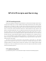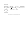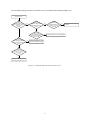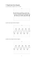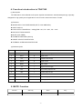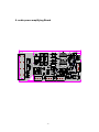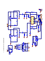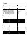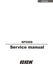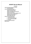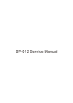
1
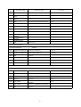
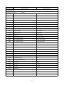
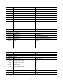
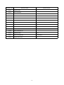
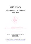
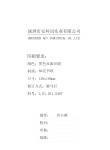
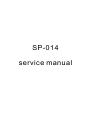
SP-014
service manual
SP-014 Principle and Servicing
1. SP-014 working principle
External input signals are inputted to input board by SC1, and its left channel signal outputs to pin 3
of socket XS through R127, to power amplifier board through flat cable XP2; after reaching power
amplifier board, it is divided into 2 paths, one path reaches potentiometer RP100A for bass adjustment
through R100 (RP100 is duplicate potentiometer, which can adjust left and right channels at the same
time); the other paths reaches potentiometer RP101A for treble adjustment through capacitor C100
(RP101 is duplicate potentiometer, which can adjust left and right channels at the same times); and the
two paths combine one path after treble/bass adjustment through resistor R108, R107 to send to
potentiometer RP102A for volume adjustment (RP102 is duplicate potentiometer, which can adjust left
and right channels); volume adjustment signals, through R101 damping and C101 coupling, are sent to
pin 11 of N100 TDA7265 for power amplifying (TDA7265 is a dual-channel power IC), then output
signals through pin 2 after amplification to loudspeaker directly. Signal floe direction of right channel is
similar with that of left channel.
This player is with power-on mute function, and its principle is: when power on, +VS charges
capacitor C110 through R110, triode V100 cuts off, MUTE pin of TDA7265 inputs high level, mute of
TDA7265 is effective, the whole set has no output; when capacitor C110 is in charging, positive voltage
increases to 6V, V100 is on, MUTE turns into low level, mute is off, output is normal and the concussion
sound is removed when power on .
2. Troubleshooting flow
(1) Troubleshooting flow for “Left channel has no output”os shown as the following figure 2.1:
-1-
Left channel has no output
Check
whether pin 1 (or
3) of power amplifier
board XS2 has waveform
after inputting
signals
N
Y
Check
whether positive
waveform of capacitor
C101 (or C111) is
normal
Y
N
Whether
waveform of pin 2, 4 of
N100 is normal
Y
N
Change RP102
Change N100
Change R127 and R129
N
Change input terminal
Figure 2.1 troubleshooting flow chart for "Left channel has no output"
-2-
Change loudspeaker
(2) Troubleshooting process for “Power no on”is shown as the following figure 2.2:
Power not on
Check
whether protector
tube on power cord has
been burnt
down
N
Y
Check
whether power
amplifier board protector
tube has been burnt
down
Check
whether power
amplifier board power
voltage +/- 22V is
normal
N
Y
Change
C120, C121,
C122, C123 and check
whether the trouble
is removed
Check
whether protector
tube of power amplifier
board has been burnt
down
N
N
N
Change N100 to solve the problem
Change transformer and
protector tube and it is O K
Y
Measure
whether power amplifier
board power cord and ground
wire impedance
is zero
Y
Change N100, transformer
and protector tube to solve
Figure 2.2 Troubleshooting flow chart for "Power not on"
-3-
Change N100 to solve the
problem
3. Signal waveform diagram
(1) Input waveform diagram of pin 11 of N100
(2) XS4 output signal waveform diagram
(3) External input signal waveform diagram
-4-
4. Function introduction to TDA7265
(1) Description
The TDA7265 is class AB dual Audio power amplifier assembled in the Multiwatt package, specially
designed for high quality sound application as Hi-Fi music centres and stereo TV sets.
(2) Features
◆ WIDE SUPPLY VOLTAGE RANGE (UP TO ?25V ABS MAX.)
◆ SPLIT SUPPLY
◆ HIGH OUTPUT POWER 25 + 25W @THD =10%, RL = 8O?, V S = +20V
◆ NO POPAT TURN-ON/OFF
◆ MUTE (POP FREE)
◆ STAND-BY FEATURE (LOW Iq)
◆ SHORT CIRCUIT PROTECTION
◆ THERMAL OVERLOAD PROTECTION
(3) PIN description
PIN No
Symbol
I/O
Description
1
-Vs
I
Negative Power Supply
2
OUT1
O
Signal out SL
3
+Vs
I
Positive Power Supply
4
OUT2
O
Signal out SR
5
MUTE
I
Mute control
6
-Vs
I
Negative Power Supply
7
IN2+
I
Non-Inverting Input Pin SR
8
IN2-
I
Inverting Input Pin SR
9
GND
I
GND
10
IN1+
I
Non-Inverting Input Pin SL
11
IN1-
I
Inverting Input Pin SL
5. MUTE Function
Function
Vmute
Stand-by
Mute
Play
+Vs-1.5~+Vs-3.5
+Vs-5~+Vs-7
Others
-5-
6. audio power amplifying Board
VD105
C122
LED1
GND
R112
N100
W12
W7
R110
VD100
W5
W8
R103
R132
C102
C106
R119
W14
C114
C108
GNDR
RP102 C113 R104
C110
W4
R117
3MM
C112
R135
R106
C104
C100
C109
C116
R108
C111
R123
RP100
C107
R118
C103
R102
R116
R129
C101
R107
R101
R130
C105
R128
R120
R113
R122
R124
XS2
R127
C120
XS4
R109
R115
R114
C115
R
G
L
R121
2006-04-17
R100
LED2
GND
XS5 L
4SP014-0
RP101
2006-04-17
1SP014-0
L
G
R
VD107
T4A L250V T4A L250V R125
W9
GND
VD104
C119
R133
R111
C124
LO
XP2
R134
W11
G
W16
W2
5MM
XS3
R131
R105
W10
W3
LED2
VD106
W15
XP3
FL101
FL100
XS1
W13 C123
R126
W1
C121
C118
W6
XC100
VD101
V100
3MM
-6-
+VS
R126
330/1W
C102
R103
3
RP102A
POT
2 R101
R100
5.6k
RP101A
POT
2
43K
XS4
1U/16V
R105 43K
R104
R102
100K
C103
471
R106
5.6k
1K
11
10
9
C105
562
8
7
R109
OUT(1)
IN-(1)
3
+Vs
GND
+VS
4
OUT(2)
IN-(2)
6
-VS
CON2
XS5
L
GND
1
2
3
LED2
R125
330/1W
-VS
+VS
R119
C109
562
1K
1.2K
43K
C114
104
R116
100K
C112
471
+VS
TREBLE
5.6K
RP101B
POT
5
56P
C113
3.3U/16V
1U/16V
R111
43K
R110
100K
4
R122
4
RP100B
POT
5R123
R132
C111
4
6
6
BASS
C115
563
RP102B
POT
5 R115
R120
4.7/1W
43K
C107
R121
5.6K
C116
562
R124
VD100
1N4148
R133
27K
VD101
5.6K
1N5404
FL100
XS1
3
2
1
VD102
1N4148
VD100
R100
XP101
1K
5R3HD
2
1
VD101
R101
CON2
1K
VD103
5R3HD
1N4148
CON2
C118
104
C119
104
+VS
+VS
C110
47U
1N5404 VD104
T4A L250V
C120
2200U/25V
C122
104
C121
2200U/25V
C123
104
VD105
T4A L250V
VD106
1N5404
FL101
VD107
1N5404
-VS
-VS
5.1V
R135
27K
V100
9014
C124
1U/50V
R112
10K
R134
200K
-7-
R118
1K
6
R114
5.6K
LED
R
GND
CON3
5
MUTE
IN+(2)
5.6k
R117
1K
GND
C108
104
+VS
1
2
TDA7269A
CON3
7. CIRCUIT DIAGRAM
2
-Vs
3
2
1
L
1
-Vs
IN+(1)
XS2
R
R113
4.7/1W
N100
1
1.2k
1
5.6k
R107
LED1
GND
1
2
CON2
R131
1K
TREBLE
RP100A
POT
2R108
3.3U/16V
1
3
3
BASS
C104
563
1K
C100
562
C101
56P
C106
XS3
8. BOM List
MATERIAL
CODE
MATERIAL NAME
SPECIFICATIONS
LOCATION
6.1 AMPLIFIER BOARD
SP-014(RU) SILVER WHITE
5448382
2100003 CONNECTED CORDS
F 0.6 SHAPED 7.5mm
W1,W4,W5,W10~W12,W14,W16
2100004 CONNECTED CORDS
F 0.6 SHAPED 10mm
W2,W8,W9,W13,W15
2100007 CONNECTION CORDS
F 0.6 SHAPEN 15mm
W3,W6
2100006 CONNECTION CORDS
F 0.6 SHAPED 12.5mm
W7
0000129 CARBON FILM RESISTOR
1/6W1K±5% SHAPED 7.5
R101,R104,R115
0000124 CARBON FILM RESISTOR
1/6W470O±5% SHAPED 7.5
R103,R118
0000130 CARBON FILM RESISTOR
1/6W1.2K±5% SHAPED 7.5
R107,R122
0000135 CARBON FILM RESISTOR
1/6W5.6K±5% SHAPED 7.5
R106,R114,R100,R108,R121,R123,R109,R1
24
0000137 CARBON FILM RESISTOR
1/6W10K±5% SHAPED 7.5
R112
0000146 CARBON FILM RESISTOR
1/6W100K±5% SHAPED 7.5
R110,R102,R116
0000141 CARBON FILM RESISTOR
1/6W27K±5% SHAPED 7.5
R133,R135
0000148 CARBON FILM RESISTOR
1/6W200K±5% SHAPED 7.5
R134
0000283 CARBON FILM RESISTOR
1/4W1K±5% SHAPED 10
R117
0000618 CARBON FILM RESISTOR
1/6W43K±5% SHAPED 7.5
R105,R119,R131,R132,R111
0000639 CARBON FILM RESISTOR
1/2W3.3O±5% SHAPED 12.5
R120,R113
0010095 METAL FILM RESISTOR
1W330O±5% SHAPED R 15×8
R125,R126
0200053 PORCELAINCAPACITOR
50V 47P±10% 2.5mm
C106,C107
0200066 PORCELAINCAPACITOR
50V 221±10% 2.5mm
C103,C112
0210031 TERYLENECAPACITOR
100V 224±10% 8mm
C118,C119
0210060 TERYLENECAPACITOR
100V 563±10% 6mm
C115,C104
0210078 TERYLENECAPACITOR
100V 562±10% 3.5mm
C100,C105,C109,C116
CL21X 100V 104±10% 5
C108,C114,C122,C123
0260025 CD
CD11 16V47U±20%5×11 2
C110
0260063 CD
CD11 50V1U±20%5×11 2
C101,C111,C124
0260019 CD
CD11 16V10U±20%5×11 2
C102,C113
0260134 CD
CD11 25V4700U±20%16×35 7.5
C120,C121 ①
0260135 CD
CD11 25V4700U±20%16×40 7.5
C120,C121 ①
0570006 DIODE
1N4148
VD100
0210109
METAL POLYESTER
FILMCAPACITOR
-8-
MATERIAL
CODE
MATERIAL NAME
0570020 DIODE
SPECIFICATIONS
LOCATION
1N5404
VD104,VD106,VD107,VD108
5.1V 1/2W
VD101
0780032 TRIODE
9014C
V100
2110336 LEAD
20# 150mm BLACK,WITH WELD PIECE
接地线
1940002 SOCKET
3P 2.5mm
XS2,XS5
1940001 SOCKET
2P 2.5mm
XS4,XS3
1940040 SOCKET
3P 3.96mm
XS1
2300006 FUSE
T4AL 250V
FL100,FL101
0580006
VOLTAGE REGULATOR
DIODE
3870057 FUSE HOLDER
ROTATED
POTENTIOMETER
ROTATED
0160036
POTENTIOMETER
0160035
1564300 PCB
FL100,FL101
D161GOAX-V1B503-016
RP100,RP101
D161GOAX-V1B503-017
RP102
@4SP014-0 UL
6.2 INPUT OUTPUT BOARD
SP-014(RU)SILVER WHITE
5448383
0000129 CARBON FILM RESISTOR
1/6W1K±5% SHAPED 7.5
R129,R127
0000144 CARBON FILM RESISTOR
1/6W47K±5% SHAPED 7.5
R130,R128
1564299 PCB
1SP014-0
2122009 FLAT CABLE
3P140 2.5 2 PIN,WITH NEEDLE, REVERSE XP3
2150106 FLAT CABLE
3P90 2.5 2 PIN,2P SHIELD,WITH NEEDLE
XP2
1910257 TERMINAL SOCKET
AV4-8.4-14-68
XC100
6.3 INDICATOR LIGHT BOARD
SP-014(RU)SILVER WHITE
5448384
0000129 CARBON FILM RESISTOR
1/6W1K±5% SHAPED 7.5
R100,R101
0570006 DIODE
1N4148
VD102,VD103
0620040 RADIATION DIODE
3B 4SC WHITE ISSUE BLUE
VD100,VD101
1940001 SOCKET
2P 2.5mm
XP101
2121489
2P230 2.5 2 PIN, WITH L NEEDLE,
REVERSE
XP101
2122174 FLAT CABLE
2P300 2.5 1 PIN,RED BLACK 20# CORD
XP101
1564301 PCB
ASP014-0
FLAT CABLE
-9-
MATERIAL CODE
MATERIAL NAME
SPECIFICATIONS
6.4 AMPLIFIER UNIT
SP-014(RU)SILVER WHITE
5462340
0881102
IC
TDA7265 Multiwatt11
0200219
CERAMICCAPACITOR
CT7 400V 103±20% 10mm
1350029
POWER SUPPLY SWITCH
PS8-11 2#
0460599
SQUARENESS TRANSFORMER
@SP-014 CQC
2140347
POWER SUPPLY CORD EUROPE SPECS
@2P 1.9m 2.5A MA-800S VDE
2300002
FUSE
T1AL 250V
5231803
CLASP
THC-5
3871936
REAR BOARD
SP-014(RU)
4660010
INVERTED TUBE
F 31×F 34×65 2#
3022122
ADJUST BUTTON
BSD02 BLACK
3580228
RADIATOR
90×90×16 SP-014
4000048
SELF-TAPPING SCREW
PB 3×8 COLOR ZINC
4000151
SELF-TAPPING SCREW
PB 3×12H COLOR ZINC
4000450
SELF-TAPPING SCREW
BT 3×6H COLOR ZINC
4000453
SELF-TAPPING SCREW
BT 3×8H WHITE NICKEL
4000387
SELF-TAPPING SCREW
PA3×12H COLOR ZINC
4210019
MACHINE-TAPPING SCREW
PWM 4×12×9 COLOR ZINC
4210048
MACHINE-TAPPING SCREW
PM 3×8 COLOR ZINC
4400002
NUT
M4
4400001
NUT
M3
4400028
NUT OF POTENTIOMETER
M7
3870634
IC PRESSING PIECE
AV220
3540074
SCREEN-SHIELDED PIECE
SP-13
4450032
ROUND PAD
F 7×12×0.5
4450014
BOLT PAD
F 4×10×0.8
4450033
BOLT PAD
f 8×15×2.5
4490002
SPRING PAD
F4
5231418
MICA PAD
22×22×0.1
5232281
INSULATED SPACER SET
F 3×6×3.2
5233838
PYROCONDENSATION SLEEVE
@F 22 UL
-10-
MATERIAL CODE
MATERIAL NAME
SPECIFICATIONS
5234967
PYROCONDENSATION SET DIPE
@F 3 UL
5234966
PYROCONDENSATION SET DIPE
@F 4 UL
5230010
NYLON BANDAGE
100mm
5180399
NOT DMETAL OXIDE FILM RESISTOR GLUE LABELL
FUSE T1AL250V
5235157
AIRPROOF STRIP
111.4×11×1 SPONGE
5235158
AIRPROOF STRIP
236.4×11×1 SPONGE
5231797
SOFT SPONGE SPACER
45×20×1.5 SINGLE-FACED,HARD
5235222
SOFT SPONGE SPACER
101.4×10×1 SINGLE-FACED SOFT
5231799
HEAT-INSULATION SPONGE SPACER
96×21.4×3 SINGLE-FACED,HARD
5448382
PCB SEMI-FINISHED PRODUCT
4SP014-0 SP-014(RU)
5448383
PCB SEMI-FINISHED PRODUCT
1SP014-0 SP-014(RU)
6.5 SPEAKER BODY WITH FOAM
MATERIAL CODE MATERIAL NAME
SPECIFICATIONS
3080518
SPEAKER BODY
SP-014(RU) MAIN SILVER WHITE
3080519
SPEAKER BODY
SP-014(RU) ASSISTANT SILVER WHITE
5041089
FOAM
FM-010142
5041090
FOAM
FM-020142
4660007
INVERTED TUBE
F 31×F 34×65
5232147
PVC PEEL
M-815A-28
6.6 SN LABEL
SP-014(RU)SILVER WHITE
5142076
MATERIAL CODE MATERIAL NAME
5142067
SPECIFICATIONS
SN LABEL
RUSSIA WITHOUT BAR CODE NUMBER
6.7 SUPPLEMENT MODULE
MATERIAL CODE MATERIAL NAME
SPECIFICATIONS
5110002
ELECTRO WELDING WIRE
F 1.0
5110018
ELECTRO WELDING WIRE
f 2.0
5110004
ADHESIVE TAPE
5110003
ELECTRO WELDING WIRE
5120096
PEANUT OIL
5120001
THINNER
5120004
SOLDERING FLUX
-11-
MATERIAL CODE
MATERIAL NAME
SPECIFICATIONS
5120011
WIPING WATER
5120012
RED GLUEWATER
5120332
SILICONE GREASE HEAT CONDUCT OIL
GB-304
5120067
GLUEWATER
502
5230021
SCOTCH TAPE
12mm
5230022
SEALING PAPER
COLORLESS
5231514
HIGH TEMPERATURE MASKING PAPER
LENGTH:15 YARD WIDTH:20mm
5231454
HIGH TEMPERATURE MASKING PAPER
LENGTH:15 YARD WIDTH:6mm
5231455
HIGH TEMPERATURE MASKING PAPER
LENGTH:15 YARD WIDTH:12mm
5231456
HIGH TEMPERATURE MASKING PAPER
LENGTH:15 YARD WIDTH:24mm
5120009
WHITE PRESSURE OIL
5230020
MASKING PAPER
24mm
5280353
SILVER LACQUER PEN
SILVER WHITE
2100002
CONNECTION CORDS
F 0.6
-12-