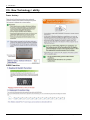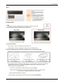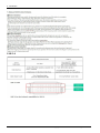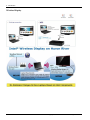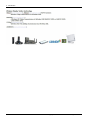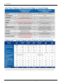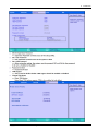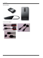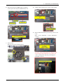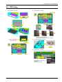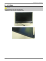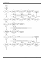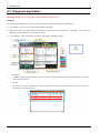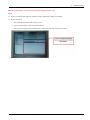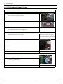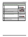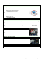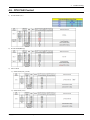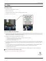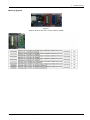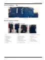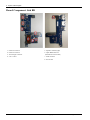
1
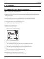
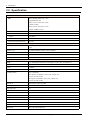
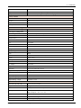
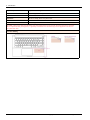
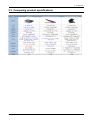
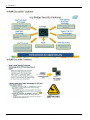
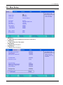
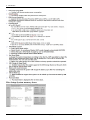
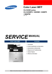
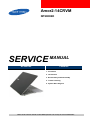
Amor2-14CRVM
NP900X4D
SERVICE
MANUAL
NP900X4D
Contents
1. Precaution
2. Introduction
3. Desassembly and Reassembly
4. Trouble shooting
5. System Wire Diagram
Refer to the service manual in the GSPN (see the rear cover) for more information.
Contents
Contents
1.
2.
3.
4.
5.
i
Precaution........................................................................................................................................ 1 − 1
1.1.
General After-Sales Service Precautions....................................................................................... 1 − 1
1.2.
Safety Precautions ................................................................................................................... 1 − 2
1.3.
Ground .................................................................................................................................. 1 − 3
1.4.
Static Electricity Precautions...................................................................................................... 1 − 4
Introduction ..................................................................................................................................... 2 − 1
2.1.
Product Features ...................................................................................................................... 2 − 1
2.2.
Specification ........................................................................................................................... 2 − 2
2.3.
Comparing product specifications ............................................................................................... 2 − 7
2.4.
Function of Product.................................................................................................................. 2 − 8
2.5.
New Technology / ability .......................................................................................................... 2 − 14
2.6.
Hardware ............................................................................................................................... 2 − 21
2.7.
Software ................................................................................................................................ 2 − 27
2.8.
Bios Setup .............................................................................................................................. 2 − 29
2.9.
HW & Option Materials ............................................................................................................ 2 − 34
Desassembly and Reassembly.............................................................................................................. 3 − 1
3.1.
Main System........................................................................................................................... 3 − 1
3.2.
TOP A’ssy .............................................................................................................................. 3 − 4
3.3.
LCD A’ssy.............................................................................................................................. 3 − 6
Trouble shooting ............................................................................................................................... 4 − 1
4.1.
General spec ........................................................................................................................... 4 − 1
4.2.
Debugging Flow Chart.............................................................................................................. 4 − 2
4.3.
Diagnosis application ............................................................................................................... 4 − 5
4.4.
System Diagnosis .................................................................................................................... 4 − 7
4.5.
Hardware Troubleshooting ........................................................................................................ 4 − 8
4.5.1.
LCD ......................................................................................................................... 4 − 8
4.5.2.
Problems related with Power ......................................................................................... 4 − 9
4.5.3.
Others ....................................................................................................................... 4 − 11
4.6.
CPU FAN Control.................................................................................................................... 4 − 14
4.7.
Other..................................................................................................................................... 4 − 16
4.8.
H/W Upgrade.......................................................................................................................... 4 − 17
System Wire Diagram ........................................................................................................................ 5 − 1
5.1.
System Layout ........................................................................................................................ 5 − 1
5.2.
System Component .................................................................................................................. 5 − 3
Copyright© 1995-2012 SAMSUNG. All rights reserved.
1. Precaution
1. Precaution
1.1. General After-Sales Service Precautions
1) Do not let customers repair the product themselves..
›
There is a danger of injury and the product life time may be shortened.
2) Make sure to disconnect the power cord from the wall outlet before repairing the product (especially for after-sales
service of electric parts).
›
There is a danger of electric shock.
3) Do not let customers plug several electric home appliances into a single wall outlet at the same time.
›
There is a danger of fire due to overheating.
4) Check if the power plug or wall outlet are damaged in any way.
›
If a defect is found, repair or replace it immediately.
(There is a danger of electric shock or fire)
5) Make sure that it is properly grounded.
(Check the ground of the wall outlet)
›
Electricity leakage may cause electric shock.
(READING S HOULD)
NOT BE ABOVE 0.5mA
LEAKAGE
CURRENT
TES TER
DEVICE
UNDER
TES T
TES T ALL
EXP OS ED METAL
S URFACES
2-WIRE CORD
*ALS O TES T WITH
P LUG REVERS ED
(US ING AC ADAP TER
P LUG AS REQUIRED)
EARTH
GROUND
Figure 1.1 Leakage Current Test Circuit
6) Do not spray water on to the product to clean it.
›
There is a danger of electric shock or fire and it may shorten the lifetime of the product..
7) Check the assembly status of the product after the after-sales service..
›
The assembly status of the product must be the same as before the after-sales service.
8) Unplug the power cord holding the power plug (and not the cord).
›
If the cord is disconnected, it may cause electric shock or fire.
9) Repair the product using only authorized parts
10) Keep the product away from heating devices such as heaters.
›
Exposure to heaters may cause deformation of the product or fire.
Copyright© 1995-2012 SAMSUNG. All rights reserved.
1-1
1. Precaution
1.2. Safety Precautions
1) EMI
This device has been registered regarding EMI for residential use. It can be used in all areas.
2) Circuit Test (Logic Test) Precautions
The LSI and MSI used in this product are semiconductor integrated circuits based on MOS-FET or CMOS. Since
these types of devices are highly susceptible to static electricity or current leakage, an isolation break may be caused.
Therefore read and follow the instructions below.
a) When handling an LSI or MSI, make sure your body is grounded through a few mega-ohms of resistance. In
addition, wear gloves and a jacket made of cotton and not of synthetic fibers that easily generate static electricity.
b) When repairing the product, place a conductive material (e.g. aluminum foil) grounded to the earth on the worktable.
c) You must use a soldering iron without a leakage current.
d) Do not touch the pin of an IC and carefully insert the IC into the black plastic package.
e) When inserting an IC into a PCB, be careful with the direction of the IC. When installing an IC in the wrong
direction, it might become damaged.
f) When carrying an IC, package the IC with conducting material such as aluminum foil or conducting sponge so as to
keep the voltage level of each of the terminals the same.
g) Since the storage temperature of an IC is between -20 ~ +70 degrees, keep it at room temperature, if possible.
h) Since the storage temperature of an IC is between -20 ~ +70 degrees, keep it at room temperature, if possible.
i) When soldering an IC, solder it in as short a time as possible so that unnecessary heat is not applied to the device.
j) Avoid leaving excessive amounts of flux within a custom IC or between the pins when soldering a custom IC.
k) Take care to not damage the board when installing or separating an Option Board.
l) Take care to not break the printed circuit pattern on the PCB when separate an IC.
1-2
Copyright© 1995-2012 SAMSUNG. All rights reserved.
1. Precaution
1.3. Ground
The product must be grounded to protect it from static electricity and other dangers. When using a multitap, please use a
multi tap with a ground terminal only.
If you use a 220V wall outlet with a ground terminal, you do not need to ground it additionally. Avoid using wall outlets if
they are not grounded even if they have a ground terminal.
To ground the product, connect the ground to an exclusive ground terminal or metal water pipe. Connect the ground cable to
the ground terminal at the rear of the main body. To ground the product, connect the ground terminal of the product to a
metal water pipe, wall outlet or exclusive ground terminal with an electric wire equal to or thicker than #18.
Never ground the product to a PVC water pipe, phone line, TV, radio antenna, aluminum window or gas pipe, because this
does not actually ground the product and may be dangerous.
Copyright© 1995-2012 SAMSUNG. All rights reserved.
1-3
1. Precaution
1.4. Static Electricity Precautions
Many parts of the system are susceptible to static electricity. Using an electrostatic discharge (ESD) device is very important
for the safety of the user and the user's surroundings. Using an ESD device increases the probability of a successful repair
and lowers the expenses for damaged parts.
To prevent static electricity, follow the instructions below.
1) Perform the repair in a location without static electricity.
2) Touch your hands to a metal water pipe or some metal object connected to the ground to discharge any static
Electricity from your body before handling the parts.
3) Touch only the edges of the board, if possible.
4) Do not touch any parts unless absolutely necessary
5) Disassemble the parts on the anti-static-electricity pad.
6) When a board is not installed in the system, package the board with an anti-static-electricity packaging.
1-4
Copyright© 1995-2012 SAMSUNG. All rights reserved.
2. Introduction
2. Introduction
2.1. Product Features
Copyright© 1995-2012 SAMSUNG. All rights reserved.
2-1
2. Introduction
2.2. Specification
Processor and Motherboard
CPU
Intel IvyBridge_BGA Type - Non
Upgradable Max spec
Intel® Core™ i7 Processor 3517U
(1.9GHz, 4 MB)
Intel® Core™ i5 Processor 3317U
(1.70Hz, 3 MBL3 Cache)
Cache
L3 : 3~6MB
Chipset
Intel HM75
BIOS
64 Mbit SPI flash
Thermal Design Performance
All 17W
Memory
Memory / Max. Memory
PC3-1066S(1333MHz),PC3-12800S(1600MHz), 2-slot SODIMM Min. 4 GB ~ Max.
8 GB
Memory type
1333MHz/1600MHz DDR3 2-Slot SODIMM
Memory Modules
2 GB SODIMM, 4 GB SODIMM (1-Slot)
Sockets
2-slot SODIMM's
※ K4B8G3346B-MCH9 (1333MHz) confirmed the competibility test
Display and Graphics
LCD
15.0" SuperBright 400nit HD+ LED Display (1600 x 900), Anti-Reflective
Type
LED LCD with Anti Glare (=Non Glare)
Panel
TN Mode
LCD Viewable Area
332.4 (H) x 186.975 (V)
LCD Resolution
HD+ (1600x900)
Win7 Support:(1600X900, 1366 X 768, 1280 X 720,
1024 X 768, 800 X 600)
XP Support :(1600X900, 1366 X 768, 1280 X 720,
1024 X 768, 800 X 600)
Dot Pitch
0.20775(H) x 0.20775(V) Mm
Viewing angle
45/45/15/30 (L/R/U/D)
Opening angle
135
Reflection Rate
Haze 25
Contrast Ratio
Typ.500
Brightness
typ.400 (cd/m2)
Response time
AM: Rising + Falling typ. 16ms
Graphics Controller
Intel HD Graphics 4000
Video Memory
Shared memory (Int) Graphics set in the BIOS setting : 64MB Windows boot : 1696MB
GPU TDP
Max.17W (CPU Integrated)
2-2
Copyright© 1995-2012 SAMSUNG. All rights reserved.
2. Introduction
Max.Resolution for LVDS
dual link resolution of 2560x2048 per link / a maximum theoretical pixel
rate of 224 MP/s MAX 2560x2048 (640x480,800x600, 1024x768, 1152x864,
1280x800,1280x960, 1280x1024, 1400x1050, 1440x900,1600x1024,1600x1200,
1680x1050, 1920x1200, 2560x2048) [Ext.monitor resolutions supported by EDID
information]
Max. resolution for VGA
Max resolution of 2560x1600 at 85Hz refresh rate (ext.) Supported
resolution MAX 2560x1600 (640x480,800x600, 1024x768, 1152x864,
1280x800,1280x960,1280x1024, 1400x1050,1440x900,1600x1024,1600x1200,
1680x1050, 1920x1200, 1920x1440,2560x1600) [Ext.monitor resolutions supported
by EDID information]
Max. resolution for HDMI
Support v1.4a compliant / a resolution of 1920x1200 pixels with 32-bit color at 60 Hz
[Ext.monitor resolutions supported by EDID information]
Controls
Keyboard Brightness Control
Audio and Video
Sound
Realtek High Definition Audio
Controller
HD Audio Codec, ALC269Q-VC-GR
Conversion
Built-in high performance 24-bit ADC & 24-bit DAC
Internal Interfaces
Embedded stereo speakers, Internal Array MIC
Speaker Power Rating
2 Speakers x 2.0 Watt with enclosure each
External Interfaces
Microphone, Headphone, Combo Jack Support( 4Pole Combo : MIC/GND/SPK/SPK
= Apple's approach), SPDIF NOT SUPPORT
Controls
Keyboard volume control, Side Volume button
Sound effect
Sound Alive
Microphone
3pole Mic/ HP combo
Type
Array Mic : DIGITAL SMD type dual array mic (Main board / Camera)
Sensitivity
-26dBFS [0dB=1V/Pa, at 1KHz]
S/N Ratio
56(min) Db
Camera
Model name
SC-13HDL11624N (IMX119P + SPCA2088)
Image sensor
1.3 Mega CMOS color image sensor
Still Image Capture Resolution
1280*1024(Max.), 1280*720, 800*600, 640*480, 352*288, 320*240, 176*144,
160*120
Video Capture Resolution
1280*1024(Max.), 1280*720, 800*600, 640*480, 352*288, 320*240, 176*144,
160*120
Frame Rate
Max 30fps @ 1.3M
Output Video Format
YUY2, MJPEG
Interface
USB 2.0
UVC Support
Compliant with USB Video Class
Storage
Type
mSATA (mini PCIe type)
Solide Stae Disk
SATA2 3.0 Gbps / SATA3 6.0Gbps
Supports
up to ATA/ATAPI-7 standard
Copyright© 1995-2012 SAMSUNG. All rights reserved.
2-3
2. Introduction
Capacity
MAX. 256GB ,128GB
Size
30*51*3.8mm, W*L*H
NAND
MLC
Optical Driver Modules (Share)
Optical Disk Driver(Option)
Ext. ODD : AA-ES3P95M
Spec
TS-U633J/SCEFZ,8X,170MS,USB,1.5MB,7.5W,5V, Blueblack
Type
Half-Finished Type 5902,
Speed
5x DVD-RAM, 8x DVD±R, 6x DVD±R DL, 8x DVD+RW, 6x DVD-RW, 24x
CD-R/RW, 8x DVD, 24x CD
Weight
130g or less
Network Tools (Share)
LAN
10/100/1000 Gigabit Ethernet LAN
RTL8111E, RJ45 output
Combo module
Intel Centrino@Advanced-N 6235
Jackson Peak2 (BA59-03294A)
Spec
6235AN.HMWG,-,2x2,Half MiniCard STD,IEEE 802.11a/g/n,26.8*30.0
Type
2X2 WLAN/BT combo module, 802.11 abg / Bluetooth 4.0 (WIDI support)
Max. Link Speed
300Mbps (Link Speed is only standard value, Actually value will decided by each
environmant)
Chipset
Jackson Peak2
Antenna
2 Antenna Support : WLAN (2TX, 2RX), BT(1TX/RX)
I/O Interface (Share)
Multi Card Slot
4-in-1 (SD, SDHC, SDXC, MMC)
vendor
Jingshi
Max. support capacity
64GB ( comfirm of the competibility test )
I/O Ports
USB Port
1 x USB 2.0 port (Chargeable, support iphone), 2 x USB 3.0 ports
VGA Port
1 x VGA dongle port
[VGA dongle is option sale.]
Audio Jacks
1 x 3.5mm Combo(HeadPhone-out, MIC-in)
LAN
1x LAN dongle port
TV
1x Combo(4 pole, HeadPhone-out, MIC-in)
[Micro HDMI to VGA dongle is not supported.]
Dock
None
Security
None
Power
2-4
1x DC-in jack(3Pie)for AC adapter
Copyright© 1995-2012 SAMSUNG. All rights reserved.
2. Introduction
Input Devices
Key board
1.35mm stroke 3.4 mm height / Backight KBD (EL sheet)
Touchpad
W98*H67.3*T0.3, PET type Click pad, Multi finger gesture
Security Solution
TPM
Trusted Platform Module 1.2
Interface
LPC
Chip
SLB 9635 TT 1.2 (infineon)
Security software
TPM Host SW
Power and Power Management
Power and Power Management
System power management
Power management features
ACPI V2.0 compliant, Standby(S3), Hibernate(S4)
Standard battery
Model code
AA-PBXN8AR
Type
Li-Polymer
Details of cell
8 cells
Battery capacity
8400mAh
Voltage
7.4V
Battery rating
60Wh
Color
Black
Dimension
309x139.4x5.6mm (W X D X H)
Weight
appox. 360 g
Recharge time
appox. 3.3 hours
AC Adapter
AD-4019P
Output Power
40W
Dimension
94 X 67 X 17mm (W x H x D)
Weight (AC Adapter)
250g (Max)
Worldwide Compatibility
Auto-sensing 100 - 240VAC
Line Frequency
50 / 60Hz
Adapter Rating - Input
90V - 264V, 1.0A
Adapter Rating - Output
19.0VDC / 2.10A
System Dimensions
Dimensions (W X D X H)
356.9 x 237.0 x 14.9 mm
Weight
1.6Kg
- Term
Full System with 8 cell Battery
Packing Size(W X D X H)
With Option : 491 * 317* 112
With out Option : 491 * 317* 112
Design
LCD Back
Mg + Teflon Coating
LCD Front
Al, Sanding + Anodizing
Copyright© 1995-2012 SAMSUNG. All rights reserved.
2-5
2. Introduction
System Top
Mg + Teflon Coating
System Bottom
Al, Sanding + Anodizing
Protection film
On Palmrest, LCD back
XP Driver
XP Driver ready, There is no plan to sell
XP TRIM
Do not support
※ TRIM, which purges data from the SSD's cells upon deletion and can prevent the slowdown that many solid state
drives experience after prolonged use, is generally considered to be the best thing to have happened to the devices
for quite some time.
Location labeling
2-6
Copyright© 1995-2012 SAMSUNG. All rights reserved.
2. Introduction
2.3. Comparing product specifications
Copyright© 1995-2012 SAMSUNG. All rights reserved.
2-7
2. Introduction
2.4. Function of Product
2-8
Copyright© 1995-2012 SAMSUNG. All rights reserved.
2. Introduction
Copyright© 1995-2012 SAMSUNG. All rights reserved.
2-9
2. Introduction
2-10
Copyright© 1995-2012 SAMSUNG. All rights reserved.
2. Introduction
Touch pad
Copyright© 1995-2012 SAMSUNG. All rights reserved.
2-11
2. Introduction
Keyboard
※ Keyboard arrangement and size can differ to by each country.
2-12
Copyright© 1995-2012 SAMSUNG. All rights reserved.
2. Introduction
Copyright© 1995-2012 SAMSUNG. All rights reserved.
2-13
2. Introduction
2.5. New Technology / ability
Inner battery
KBD Function
2-14
Copyright© 1995-2012 SAMSUNG. All rights reserved.
2. Introduction
ALS
Gesture Pad
Copyright© 1995-2012 SAMSUNG. All rights reserved.
2-15
2. Introduction
USB 3.0
2-16
Copyright© 1995-2012 SAMSUNG. All rights reserved.
2. Introduction
Copyright© 1995-2012 SAMSUNG. All rights reserved.
2-17
2. Introduction
Wireless Display
2-18
Copyright© 1995-2012 SAMSUNG. All rights reserved.
2. Introduction
Copyright© 1995-2012 SAMSUNG. All rights reserved.
2-19
2. Introduction
2-20
Copyright© 1995-2012 SAMSUNG. All rights reserved.
2. Introduction
2.6. Hardware
Intel’s 2012 Mobile Platform : Chief River
Copyright© 1995-2012 SAMSUNG. All rights reserved.
2-21
2. Introduction
2-22
Copyright© 1995-2012 SAMSUNG. All rights reserved.
2. Introduction
Copyright© 1995-2012 SAMSUNG. All rights reserved.
2-23
2. Introduction
2-24
Copyright© 1995-2012 SAMSUNG. All rights reserved.
2. Introduction
Copyright© 1995-2012 SAMSUNG. All rights reserved.
2-25
2. Introduction
WLAN
SSD
2-26
Copyright© 1995-2012 SAMSUNG. All rights reserved.
2. Introduction
2.7. Software
Driver LIST
Item Name
Chipset (Chief River )
Realtek ALC26X Windows7 Sound Driver
Intel Ivybridge Win7 32bit GFX Driver
Intel Ivybridge Win7 64bit GFX Driver
Windows7-Realtek LAN Driver[Gigabit]
NEC (Renesas) USB 3.0 Host Controller Driver
Driver
Intel Rapid Storage Technology
Realtek ALC26X Windows7 Sound Driver
Intel WLAN Driver with myWiFi (s32)(14.2.1.1 WIFI)
Intel Bluetooth Driver (Win7)(2.1_PSTOBE)
Heci(Chief River,SWDESC)_Package
Infineon TPM Utility
Touchpad- Elan (ETD0B00)(1.0)
Easy Settings 1.1
Easy Settings 1.1 for Amor2/Lotus Fast Boot
KBD Launguage Exchanger (ENG/RUS)
sogou (with ENG/CHN KBD exchanger)
Easy Migration 1.0
Software Launcher 1.1
Fast Browsing for IE9
Samsung Theme (Premium)
Design Movie cliip
AnyWeb
Universal Printer/Sacnner Driver
Easy Partition Manager 2.2
Application
Electronic Manual
Interactive guide
EPOP
MultiMedia POP
Survey Icon
Easy File Share 1.2
Smartview 1.0
Allshare 2.1
Easy Support Center 1.2
Easy Software Manager 1.2
Samsung Recovery Solution 5.0
Samsung Internet Service Short cut
Copyright© 1995-2012 SAMSUNG. All rights reserved.
2-27
2. Introduction
Samsung.com short cut
Windows Live 4 QFE2
MS Bing Toolbar 7.0
MSN Homepage
WildTangent Game Console
Norton Internet Security 2012 (EXP: 60 days Trial, KOR : 1Year Trial)
Norton Online Backup (30-day Trial)
Skype
Kindle for PC
Adobe Reader 10 (MUI )
Cyberlink Youcam 3.1
Intel Wireless Display
Absolute Data Protection
Infineon TPM Professional Package
Software-Previous/New
※ For more information, product descriptions and installation training manuals refer to Chap.1
Consultation stage of development
※ Consultation of development stage. (Known Issue & Spec)
Please refer that [Consulting Script] → [Consultation]
2-28
Copyright© 1995-2012 SAMSUNG. All rights reserved.
2. Introduction
2.8. Bios Setup
Copyright© 1995-2012 SAMSUNG. All rights reserved.
2-29
2. Introduction
Bios Setup-System memory share
2-30
Copyright© 1995-2012 SAMSUNG. All rights reserved.
2. Introduction
Copyright© 1995-2012 SAMSUNG. All rights reserved.
2-31
2. Introduction
2-32
Copyright© 1995-2012 SAMSUNG. All rights reserved.
2. Introduction
Copyright© 1995-2012 SAMSUNG. All rights reserved.
2-33
2. Introduction
2.9. HW & Option Materials
Basic Item
2-34
Copyright© 1995-2012 SAMSUNG. All rights reserved.
2. Introduction
Option Materials
※ mouse is currently being developed. Code and description will be updated later.
Copyright© 1995-2012 SAMSUNG. All rights reserved.
2-35
2. Introduction
Wireless Mouse
VGA & LAN Adapter
2-36
Copyright© 1995-2012 SAMSUNG. All rights reserved.
2. Introduction
Copyright© 1995-2012 SAMSUNG. All rights reserved.
2-37
3. Desassembly and Reassembly
3. Desassembly and Reassembly
3.1. Main System
CAUTION
4. Disconnect Speaker/Fan/DC Jack/ LCD Cable
Disconnect cables in the areas circled
Turn off the system before disassembly.
1. Disassemble Bottom
Loosen 10 screws in order of (8ea) -> (2ea) to separate
the system bottom.
5. Remove Subboard FPC
Carefully remove subboard FPC not to damage the
connector. Also, carefully detach double-sided tape on
the bottom side of the FPC.
2. Disassemble Battery
Remove 7 screws to separate Battery from the system.
3. Battery connector
Pull the battery connector to remove battery.
3-1
Copyright© 1995-2012 SAMSUNG. All rights reserved.
3. Desassembly and Reassembly
6. Disconnect Keyboard, KBD backlit, Touchpad
8. Unplug antenna and unscrew wireless LAN module
From right to left: Keyboard, KBD backlit, T/P
9. Remove Main/Sub board by unscrewing screws in red
circle.
SSD – 1 screw / Subboard – 3 screws / Mainboard –
5 screws
7. Remove Fan
Remove two screws to detach the fan
※ Caution: When reassembling the subboard, make
sure the board is fixed under the rib circled in red.
: Power switch/power LED may be damaged if
assembled on the rib.
Copyright© 1995-2012 SAMSUNG. All rights reserved.
3-2
3. Desassembly and Reassembly
10. Heatsink disassembly
Remove 5 screws to disassemble heatsink.
12. Separate Hinge
When changing LCD Ass’y, remove 6 screws on the
hinge to separate the LCD and top.
11. Removing memory module
Pull two hooks on the side to remove memory module.
※ Refer to this section backwards for resassembly
3-3
Copyright© 1995-2012 SAMSUNG. All rights reserved.
3. Desassembly and Reassembly
3.2. TOP A’ssy
1. TOUCHPAD Assembly
2. SUB PART Assembly
3. AUDIO GUIDE Assembly
4. ANTENNA Assembly
Copyright© 1995-2012 SAMSUNG. All rights reserved.
3-4
3. Desassembly and Reassembly
5. 3 in 1 Assembly
3-5
Copyright© 1995-2012 SAMSUNG. All rights reserved.
3. Desassembly and Reassembly
3.3. LCD A’ssy
CAUTION
※ LCD is assembled as a whole unit. Cannot disassemble.
- LCD panel of the open cell structure. So will not be reused.
Copyright© 1995-2012 SAMSUNG. All rights reserved.
3-6
4. Trouble shooting
4. Trouble shooting
4.1. General spec
Tools used for repairing the product.
• System Diagnostics Disk
• MS-DOS Booting Disk
• System Diagnostics Card
• Screwdrivers (+, —)
• Tweezers
• Multi-meter
• Oscilloscope / Logic Analyzer
Replace Units (FRU: Field Replaceable Unit)
• DDR3 RAM Module
• 2.5" SATA HDD
• Wlan module / Bluetooth Module
• System Fan
• LCD Panel
• Main Board
• System Fan
• Key Board
• Touch Pad
• Modem
• 0.3M Camera module
• Cables
• LCD Panel / LCD Inverter
4-1
Copyright© 1995-2012 SAMSUNG. All rights reserved.
4. Trouble shooting
4.2. Debugging Flow Chart
Debugging Flow of Samsung’s computer product is universal between products.
Refer to attached Debugging Flowchart for more contents.
Copyright© 1995-2012 SAMSUNG. All rights reserved.
4-2
4. Trouble shooting
4-3
Copyright© 1995-2012 SAMSUNG. All rights reserved.
4. Trouble shooting
Copyright© 1995-2012 SAMSUNG. All rights reserved.
4-4
4. Trouble shooting
4.3. Diagnosis application
※Training manual how to use the side of the fault diagnosis please refer.
WinDiag4
1) WinDiag4 is a Diagnostic tool that tests overall computer’s H/Ws and functions for Windows 7.
2) Precondition : UAC(User Account Control) should be disabled.
3) Installation : When you double-click SvcDiag.bat file, this program will be installed in C:\WinDiag4. After installation,
WinDiag4 will automatically start testing the system.
4) Uninstallation : After terminating the program, Just delete C:\WinDiag4 folder.
•
: Group Info
- It displays Group Item Name and Test Count. If there is any FAIL or FAULT in the Group Item, the color of title
will be changed to Red.
•
: Test Item
- §It displays Test items included in this Group. If there is any FAIL or FAULT in this test item, the color of the
test item will be changed to Red.
4-5
Copyright© 1995-2012 SAMSUNG. All rights reserved.
4. Trouble shooting
※Training manual how to use the side of the fault diagnosis please refer
Pyxis
1) Pyxis is a software that diagnose computer’s H/W components in DOS environment.
2) How to use Pyxis
•
First, make Dos bootable USB memory or CD.
•
Copy all released files to the Dos bootable device.
•
After you boot using the Dos bootable device, Select the menu that you want to execute.
Copyright© 1995-2012 SAMSUNG. All rights reserved.
4-6
4. Trouble shooting
4.4. System Diagnosis
System Diagnostics Card
The Diagnostics Card shows the system operations during the POST (Power On Self Test) in a 2 digit hexadecimal number
by connecting the cable to the 10 pin connector below the PCMCIA slot after separating the Top part. The card is used to
evaluate the reason for the malfunction without disassembling the system when the system malfunctions and to test if the
system operates normally after replacing a defective FRU.
Debugging Code
In general, if a defect of the circuit or part is detected during the system test, the system stops at a particular code.
The error codes for each part of the system are listed in the following table.
※ ※Please Refer to the Training manual chapter4.Trouble Shooting
4-7
Copyright© 1995-2012 SAMSUNG. All rights reserved.
4. Trouble shooting
4.5. Hardware Troubleshooting
4.5.1. LCD
1. The screen is dark or the colors of the screen are distorted..
Check the connection status
- LCD Cable on Main board side connector
→ Make sure Cable is inserted correctly
1
Check if there is a part of the LCD that is bent or broken due to impact.
2
→ Replace the front Ass’y
Copyright© 1995-2012 SAMSUNG. All rights reserved.
4-8
4. Trouble shooting
4.5.2. Problems related with Power
1. The system cannot power on
1
Check if the adaptor is plugged in. Battery might be in shipping mode.
2
Check if DC Cable is plugged in correctly.
Check if battery is plugged in correctly.
3
Check Riht Sub-FPC connection.
4
5
6
Change Right Sub-FPC or Sub board
Check BIOS ROM status using debugging card
→ If BIOS ROM is NG, change main board
2. the system does not boot or immediately turns off after being turned on.
Since this may be a short circuit in the
1
system
Disconnect the power immediately,
disassemble the system and check if
there are any conducting alien objects
such as a screw inside.
Check the connection status between the CPU and the RHE.
2
3
RTC Reset.
* Check if it is out of order.
4
Replace Main Board.
* Check if it is out of order.
3. The system battery is not recharged.
1
Check if DC Cable is plugged in correctly
→ If not, plug in the DC cable.
Check if Battery is plugged in correctly
2
→ If not, plug in the Battery
3
Change DC cable
4
Change DC cable
4-9
Copyright© 1995-2012 SAMSUNG. All rights reserved.
4. Trouble shooting
4. The system can power on, but cannot boot into Windows
1
Make sure no USB storage device is connected to the USB port
2
If the 'Operating system not found'message appears during the booting
process even though the SSD is recognized by CMOS, the operating system
of the SD may be corrupted or the SSD is out of order.
Format the SSD and reinstall the
operating System.
If problem persists, replace SSD
5. The system can power on, but LED on power button does not lit up.
1
Check if there is any material blocking the LED
2
Change Power switch FPC
Change Sub board
3
Copyright© 1995-2012 SAMSUNG. All rights reserved.
4-10
4. Trouble shooting
4.5.3. Others
The system does not recognize USB devices
1
Make sure the USB device receives enough power (some USB devices
need external power source)
Check USB FPC connection on main board. Change if necessary
2
3
Replace main board
TP function is abnormal, or does not work
1
Try checking PS/2 Port Touch pad driver in control panel
Make sure TP cable&PCB is connected
2
3
Change front Ass’y
KBD function is abnormal, or does not work
1
Try checking KBD driver in control panel
2
Check lighting of Caps Lock & WLAN LED
3
Check KBD FFC & KBD backlit FPC connection
4
Check bios setting
5
Change main-board
Camera function is abnormal, or does not work
1
Check device manager and make sure camera driver (under imaging
devices) is loaded correctly
Check LCD cable connection
2
3
4-11
Change LCD assy
Copyright© 1995-2012 SAMSUNG. All rights reserved.
4. Trouble shooting
Problems related to sound
1. There is no sound from the speaker.
(Insert the figure of the audio jacks so that the reader can check via the figure.)
Check if the sound is muted after booting up Windows.
1
2
Control panel confirmation.
→ Speaker Setting.
3
Check the connection status of the speaker cable and check if the speaker is
out of order.
4
Check if there is a magnetic object near the speaker.
5
Replace Speaker.
* If there is still no function, change
main + sub board
2. There is no sound from the headphone/mic.
Check if the sound is muted after booting up Windows.
1
2
Control panel confirmation.
→ Speaker Setting.
3
Check main board around audio connector.
Check for any short circuit or soldering NG.
4
Change main board
Copyright© 1995-2012 SAMSUNG. All rights reserved.
4-12
4. Trouble shooting
HDMI port does not work normally.
System manager confirmation .
1
(Video / Sound / Controller confirmation)
→ HDMI driver Re-install.
Check the Display Manager work normally.
→ Display Manager program Re-install.
2
3
4
Check the Control panel .
→ Check HDMI section enable.
Replace Main Board.
AP (WLAN) or B / T devices can not connect.
If the driver loaded correctly, check in Device Manager.
When loaded, AP signal is strong
confirmation.
1
2
Make sure that the BT unit power. Or
Check the connection to another host.
Wireless antenna connection or check the status of damage.
3
Wireless Lan module connection or check the status of damage
4
Check wlan module connector damage
Antenna change
Change Wireless LAN module
Main-board change
5
The system temperature is too high.
1
Check the system by using SAFC(Samsung Advanced Fan Control)program.
2
Check the connection status of Heat sink
* Tool Program reference
→ Screw 5EA
3
Check the connection status of FAN
Screw 4EA (R/L each 2EA)
4
Replace FAN
* Check if it is out of order.
5
Replace RHE
* Check if it is bent.
6
Replace Main Board.
* Check if it is out of order.
4-13
Copyright© 1995-2012 SAMSUNG. All rights reserved.
4. Trouble shooting
4.6. CPU FAN Control
1) Normal Mode (AC)
2) Normal Mode(Battery)
3) Silent Mode
a) Silent Mode(Auto_on/off)
b) Silent Mode (Low)
Copyright© 1995-2012 SAMSUNG. All rights reserved.
4-14
4. Trouble shooting
CPU Fan Control
- One can turn the fan on & off and check the fan's operational conditions without system disassembly.
- SAFC's default setting is "Fan off" or "Minimum Fan Speed".
- Press "ON" in "ON/OFF Control" Fan is turned on to maximum fan speed.
- Press "OFF" in "ON/OFF Control" Fan returns to default setting.
• Fan Voltage Measurement
- Read Fan RPM indicated in SAFC.
• Fan Voltage Pass/Fail determination
- If Fan RPM satisfies "rpm spec +/-10%", then Fan test is "PASS" .
4-15
Copyright© 1995-2012 SAMSUNG. All rights reserved.
4. Trouble shooting
4.7. Other
RTC Battery Reset
• The system apart and remove the battery.
• Remove the RTC battery
• Using the tool like as tweezer, connect two nodes for about 20~30sec.
• Then Bios rom will be reseted.
Check the battery use environment
1) Generally, the battery usage time in advertisements by notebook manufacturers refers to the maximum battery use time.
Since the system specifications and the usage environment may differ, the user's battery usage time may differ from the
advertisement even if there is no problem with the system.
2) Conditions for the company's maximum battery use time
a) Minimum LCD brightness, base system, the wireless LAN R/F is turned
off, BatteryManager-Maximum Battery Mode
b) Measuring Tool: BatteryMark v.4.0.1
3) If a customer complains about the battery usage time, let them know that the battery usage time may differ depending
on the model specifications and the usage environment and recommend the following usage environment for longer
battery time.
a) Use the company's power-saving program, BatteryManager, and set BatteryManager to Maximum Battery Mode.
b) LCD brightness: Set to the minimum level as long as the user does not experience inconvenience.
c) Disable unnecessary devices
d) Turn the wireless LAN R/F switch off and disable USB devices (DMB, fingerprint recognition and Bluetooth)
Refer to attachment The method of Battery check.
※ Please Refer to the Training manual chapter4.Trouble Shooting.
Copyright© 1995-2012 SAMSUNG. All rights reserved.
4-16
4. Trouble shooting
4.8. H/W Upgrade
HDD Upgrade
4-17
Copyright© 1995-2012 SAMSUNG. All rights reserved.
4. Trouble shooting
Memory Upgrade
Memory
: Pull two hooks on the side to remove memory module.
Copyright© 1995-2012 SAMSUNG. All rights reserved.
4-18
5. System Wire Diagram
5. System Wire Diagram
5.1. System Layout
1. System Layout
2. LCD Layout
5-1
Copyright© 1995-2012 SAMSUNG. All rights reserved.
5. System Wire Diagram
3. Height Simulation
4. KBD
Copyright© 1995-2012 SAMSUNG. All rights reserved.
5-2
5. System Wire Diagram
5.2. System Component
5-3
Copyright© 1995-2012 SAMSUNG. All rights reserved.
5. System Wire Diagram
Board Component — Top
1. ALS sensor
2. Audio chip
Board Component- Bottom
1. CPU
2. PCH
3. SODIMM Memory connector
4. WLAN mini card
5. 60pin B2B connector
6. RTC battery
7. Touch pad connector
(Sub-board to main-board)
9. DC in cable connector
10. LCD connector
8. Battery connector
12. TPM
13. Micom
11. KBD connector
15. Fan connector
16. BIOS ROM
14. Keyboard Backnit connetor
18. Audio combo jack
19. m-HDMI connector
17. USB 2.0 connector
21. Speaker connetor(left)
22. Mic chip
20. LAN dongle connector
Copyright© 1995-2012 SAMSUNG. All rights reserved.
5-4
5. System Wire Diagram
Board Component- Sub BD
1. USB 3.0 connector
5. Speaker connetor(right)
2. USB 3.0 connector
6. 60pin B2B connector
3. VGA dongle connector
(Sub-board to main-board)
4. 4 in 1 socket
7. SSD connector
8. Power S/W
5-5
Copyright© 1995-2012 SAMSUNG. All rights reserved.
GSPN (GLOBAL SERVICE PARTNER NETWORK)
Area
Web Site
Europe, MENA,
CIS, Africa
https://gspn1.samsungcsportal.com
E.Asia, W.Asia,
China, Japan
https://gspn2.samsungcsportal.com
N.America, S.America
https://gspn3.samsungcsportal.com
This Service Manual is a property of Samsung Electronics
Co.,Ltd.
Any unauthorized use of Manual can be punished under
applicable International and/or domestic law.
© 2012 Samsung Electronics Co.,Ltd.
All rights reserved.
Printed in Korea
Code No.: