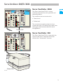
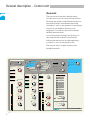
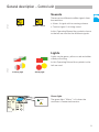
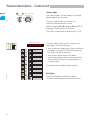
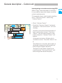
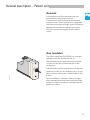
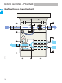
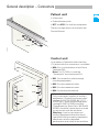
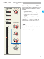
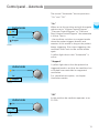
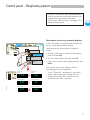
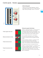
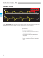
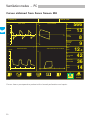
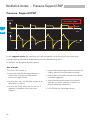
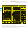
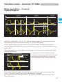
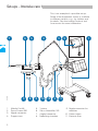
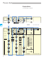
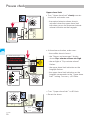
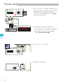
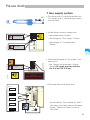
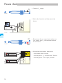
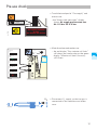
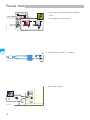
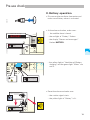
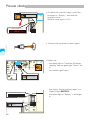
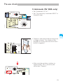
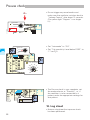
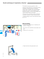
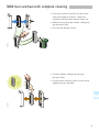
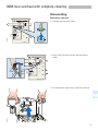
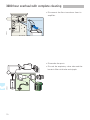
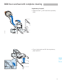
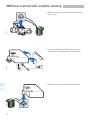
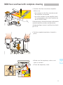
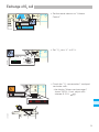
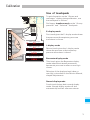
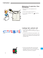
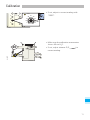
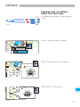
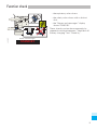
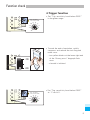
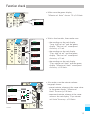
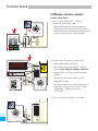
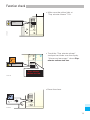
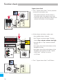
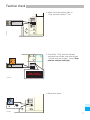
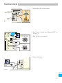
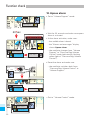
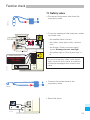
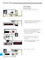
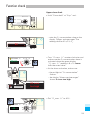
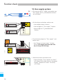
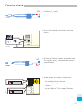
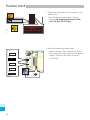
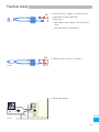
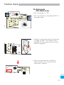
1
SERVO VENTILATOR 300/300A
CRITICAL CARE
OPERATING MANUAL 8.1/ 9.1
SERVO VENTILATOR 300/300A OPERATING MANUAL 8.1/ 9.1
Servo Ventilator 300/300A – Operating Manual 8.1/9.1
Art.-Nr. 64 08 004 E313E
© MAQUET Critical Care AB, Electromedical Systems Division,1996-2000. All rights reserved. No part of this
publication may be reproduced, stored in a retrieval system, or transmitted in any form or by any means,
electronic, mechanical, photocopying, recording, or otherwise, without the prior permission of the copyright
owner i writing. Subject to alterations without prior notice.
Issued by MAQUET Critical Care AB, SE-171 95 SOLNA, Sweden.
Printed in Sweden.
Price: Group 6.
0109 1.5
5th English edition,
June 2000.
ode
Autom
On
Off
por t
Sup
21
Adu lt
c
Ped iatri
Neo nate
15
261
5
19
11
2
19
1 . 13
0 . 35
5.0
259
266
5.1
lator
Servo
SIE ME
NS
Venti
300 A
Notes
Important
The Servo Ventilator 300/300A is not designed to withstand severe
negative pressures. If a negative suction pressure exceeding 100 cm
H2O (-100 cm H2O) is applied to the system, the pressure transducers
may be damaged causing the system to become inoperable.
Observe the following for the Servo Ventilator 300/300A.
When using closed system suctioning:
• If the suctioning flow is higher than that which is delivered by the
ventilator, a negaitve pressure may be generated which will be
applied to the lung and the ventilator breathing system.
• Do not use the Stand by position, Inspiratory pause hold, or
Expiratory pause hold during the closed suctioning procedure.
Function test for ”Insp. time %”
and ”PEEP” potentiometers
Insp. time %
• Set ”Insp. tid %” to 80 %.
Insp. time %
Insp. period s
• Turn the knob slowly counter-clockwise to
10% simultaneously watch the reading on
the display ”Insp.period s” . The reading
must decrease evenly, digit by digit,
without any sudden jumps (up or down).
• Set ”Insp. time %” back to 25 %.
PEEP
PEEP
• Set ”PEEP” to 50 cm H2O.
• Turn the knob slowly counter-clockwise to
0 cm H2O. Simultaneously watch the two
diodes showing preset PEEP as well as
the two diodes showing actual pressure
on the ”Airway pressure” bargraph. The
values indicated must follow each other
evenly, decreasing step by step, without
any sudden jumps (up or down).
Automode
O2 conc. %
Press. Reg. Vol.
Control/Support
Mians
Adult
Volume
Control/Support
Neonate
Airway press.
60 70 80
27
90
100
40
110
30
20
Mean
Ventilator off
Battery charging
Measured freq.
b/min
Pause
21
20
Set freq.
b/min
End. Exp.
Pressure Control
Level above PEEP
20
70
80
20
100
Pressure Support
Level above PEEP
40 50 60
70
80
20
50
0
PEEP
15
40
45
5
0
20
10
0
-2
0
-14
-16
-10
-20
3000225E
8
10
SIMV freq. b/min
8 12 16
5
20
25
2,5
1
O2 concentration
499
Exp. minute
volume
498
Apnea
Exp. minute vol.
l/min
Gas supply
9.9
Battery
2
20
1,8
18
1,6
16
1,4
14
1,2
12
1
10
0,8
8
0,6
6
40
0,4
4
0,2
2
0
0
Technical
Upper alarm limit
25 30 35
20
40
Reset
45
15
50
10
5
60
2 min
55
Alarm limits
Neonate 1/10
20
25
15
Pause hold
Insp.
30
10
30
0,5
%
Airway
Pressure
9
0
40
Insp. tidal vol.
ml
l/min
7
1
50
Trig. sensitivity
Level below PEEP
-8 -6
-4
-10
-12
3
2
02
500
25
30
Insp. rise time %
4 5 6
35
10
30
Pause time %
15
20
10
0
Alarms and messages
Exp. tidal vol.
ml
80
5
Volume
Minute vol.
l/min
70
10
100
20 25 30
40
0 . 68
60
90
10
60
1 . 06
Volume
Tidal vol.
ml
10 . 0
50
30
25
20
Insp. flow l/s
30
70
Insp. period s
90
10
80
Oxygen breaths
Start breath
Insp. time %
40
30
90
Support
Optional
CMV freq. b/min
70 80 90
60
100
50
110
40
120
30
130
20
140
10
150
40 50 60
0
Off
120
18
5
100
Oxygen breath running
Pressure Support
CPAP
Stand by
50
Peak
90
21
SIMV (Press. Contr.)
+ Pressure Support
On
80
30
Upper press. limit
cm H2O
70
40
40
SIMV (Vol. Contr.)
+ Pressure Support
Pressure
Control/Support
60
50
!
Pediatric
100
Volume Support
35
5
Exp.
40
Lower alarm limit
Servo Ventilator 300 A
Log sheet
Leakage test
Pressure levels
Log sheet
Date and
signature
Trigger function
Upper pressure limit alarm
Tidal and minute volumes
Minute volume alarms
Check of neonate range
Exchange parts
Check tubings alarm
Date and
signature
Apnea alarm
Safety valve
O2 alarm
Gas supply system
Battery operation
Automode
Date and
signature
Cleaning
Autoclaving
Exchange parts
Date and
signature
Leakage test
Upper pressure limit alarm
Minute volume alarms
Apnea alarm
O2 alarm
Gas supply system
Battery operation
Exchange parts
Date and
signature
Automode
Date and
signature
Cleaning
Autoclaving
Exchange parts
Date and
signature
Date and
signature
Important
General information
Connection
• The symbol
on the unit means:
Attention, consult accompanying
documents.
• A pre-use check must always be done
before connecting the ventilator to a
patient.
• The information in this Operating Manual
is valid for Servo Ventilator 300 8.1 and
Servo Ventilator 300/300A 9.1 unless
stated otherwise.
• When connected to a patient, the
ventilator must never be left unattended.
• The Servo Ventilator 300/300A must be
operated only by authorized personnel
who are well trained in its use. It must be
operated according to the instructions in
this Operating Manual.
• The Servo Ventilator 300 can have
different software versions lower than 8.0
with corresponding versions of the
Operating Manual. Before use, make sure
the information on the label on the control
unit corresponds to the version number
on the Operating Manual.
• After unpacking, perform a function check
and, if necessary, a calibration.
• All data on pressures for Servo Ventilator
300/300A are given in cm H2O.
1 kPa (kilopascal N10 cm H2O
100 kPa = 1 bar N 1 atm N
1 kgf/cm2 (kp/cm2)
100 kPa N15 psi
• Responsibility for the safe functioning of
the equipment reverts to the owner or
user in all cases in which service or repair
has been done by a non-professional or by
persons who are not employed by or
authorized by MAQUET, and when the
equipment is used for other than its
intended purpose.
• Documentation for the Servo Ventilator
300/300A consists of:
– Operating Manual
– Service Manual
– Spare Parts Catalogue
– Circuit Diagram
• Accessories and auxiliary equipment must
not be connected or disconnected during
operation or when the ventilator is
connected to mains. Such connection or
disconnection may interfere with the
functioning of the ventilator.
• All gases must fulfill the specifications for
medical grade gas. The gases supplied
must be free from water, oil and particles.
Air ....................................... H2O < 5 mg/m3
Oil < 0.5 mg/m3
Oxygen ............................. H2O < 20 mg/m3
Operation
• To protect the patient against high airway
pressures, the “Upper press. limit” must
always be set according to the operating
instructions so as to provide adequate
patient safety.
• The “Upper alarm limit” and “Lower
alarm limit” for minute volume must
always be set according to the operating
instructions so as to provide adequate
patient safety.
• If a Bi-Phasic Ventilation Module for
SV 300 is connected to a Servo Ventilator
300A the “Automode” must be turned
off.
• The “Automode” must be turned off if
two SV 300A are connected with a
synchronization cable for Master-Slave
application.
• During operation the water traps must be
checked regularly and if necessary
emptied.
Important
•
The device complies with the
requirements of the Medical Device
Directive 93/42/EEC.
0413
• Regarding electromagnetic compatibility
it is the responsibility of the user to take
necessary measures in order to ascertain
that the specified limits are not exceeded
as this may impair the safety of the
ventilator.
Such measures should include, but are
not limited to:
– Normal precautions with regard to
relative humidity and conductive
characteristics of clothing in order to
minimize the build-up of electrostatic
charges.
– avoiding the use of radio emitting
devices in close proximity to the
ventilator, such as high-frequency
surgery apparatus or cordless (mobile)
telephones, resulting in a field level
exceeding 3 V/m (IEC 601-1-2)
• Magnetic fields of MR equipment having
flux densities above 20 mT may cause
deactivation of the ventilator functions
and may result in permanent damage to
the Servo Ventilator.
• The apnea alarm is not intended to and
will not monitor for disconnections.
• The apnea alarm is not functional in the
modes “Volume Control/Support”,
“Pressure Control/Support”, or “Pressure
Reg. Volume Control/Support”.
• As an extra safety a resuscitator must
always be readily accessible.
• This lung ventilator is not intended to be
used with any anesthetic agents.
• Antistatic or electrically conductive
breathing tubes should not be used with
this lung ventilator.
Service
• The Servo Ventilator 300/300A must be
serviced at regular intervals by specially
trained personnel. Any maintenance must
be noted in a log book provided for that
purpose in accordance with national
regulations. We recommend that service
is done as a part of a service contract with
MAQUET.
• A 1000 hour overhaul must be performed
after 1000 hours of operation or, at the
latest, every six months. In addition, the
ventilator shall undergo a technical safety
check (Function check) twice a year, at six
month intervals or according to national
regulations.
• A 3000 hour overhaul must be performed
after every 3000 hours of operation or, at
the latest, once every year.
• The internal battery shall be replaced
every 3 years according to instructions in
the Service Manual. The batteries can only
be guaranteed if they are used only as a
back-up at mains failure approx. 30 min.
• Service and repair of the ventilator may be
done only by MAQUET-authorized
personnel.
• Only original parts from MAQUET must be
used in the ventilator.
• Old non-functioning batteries
O2 cells must be returned to the
place of purchase or to a place
where they can be disposed of
properly. Batteries and O2 cells must not
be disposed of with ordinary waste.
and
Important
Cleaning
• The ventilator must not be gas sterilized.
• The flow transducer must not be cleaned
in a dish washing machine, by ultrasonic
methods or by using agents that contain
aldehydes.
• Agents used for cleaning must have a pH
between 4 – 8.5.
• Complete cleaning should be done after
every 3000 hours of operation or, at the
latest, once every year according to chapter
3000 hour overhaul with complete
cleaning.
Accessories and auxiliary equipment
• Only accessories, supplies or auxiliary
equipment (“Products and accessories”
catalogs 64 74 725 E323E, 64 74 717
E323E and “Spare and exchange parts”
catalog 90 34 570 E323E including
"Supplement for Spare Parts" 64 08 822
E404E) should be connected to or used in
conjunction with the ventilator.
Warning: Use of accessories and auxiliary
equipment other than those specified in
the documents mentioned above may
result in degraded performance and safety
of the ventilator.
• If a Bi-Phasic Ventilation Module for SV 300
is connected to a Servo Ventilator 300A the
“Automode” must be turned off.
• Values measured at the signal outputs of
the Servo Ventilator 300/300A and which
have been processed in auxiliary
equipment must not be used as a
substitute for therapeutic or diagnostic
decisions. Such decisions can be made
only by staff with medical expertise,
according to established and accepted
practice. If auxiliary equipment that has not
been manufactured by MAQUET is used,
MAQUET denies all responsibility for the
accuracy of signal processing.
• If there should be any deviation between
information shown on the front panel of the
ventilator and that shown by the auxiliary
equipment, the ventilatory parameters shown
on the front panel shall be considered the
primary source for information. It is the
responsibility of the user to ensure that any
accessories, supplies and auxiliary equipment
are compatible with the ventilator and that
their use does not affect the normal
functionality of the ventilator. In case of
doubt, contact a MAQUET representative.
Accessories, supplies and auxiliary
equipment that are not compatible with
Servo Ventilator 300/300A may interfere with
the functioning of the ventilator.
• If a front panel cover is used, do not attach
anything (e.g. stickers) on the cover. Vital
information can then be hidden impairing
patient safety.
List of contents
General description...................................................
Control Panel ............................................................
Ventilation modes .....................................................
Patient safety............................................................
Set-ups and connection to patient ............................
Pre-use check ...........................................................
Troubleshooting ........................................................
Quick exchange of expiratory channel ......................
Routine cleaning .......................................................
1000 hour overhaul ...................................................
3000 hour overhaul with complete cleaning .............
Exchange of O2 cell ..................................................
Calibration .................................................................
Function check .........................................................
1
General description
Contents
System SV 300 .......................................... 2
Servo Ventilator 300/SV 300A .................. 3
Control unit
General ................................................... 4
Sounds ................................................... 5
Lights ..................................................... 5
Displays ................................................. 7
Knobs .................................................... 7
Touchpads ............................................. 9
Set Parameter Guide ............................ 10
Conversion tables for flow
and volume .......................................... 13
Patient unit
General ................................................. 15
Gas modules ....................................... 15
Gas flow through the patient unit ......... 16
Technical specifications ......................... 18
Labels .................................................. 22
Connectors .......................................... 23
1
System SV 300
The Servo Ventilator 300/300A is the main
part of the System SV 300, a versatile
system for the critically ill patient.
This system offers a wide range of products
and accessories, e.g., carts, breathing
systems, compressors, external power
supply, humidifiers, a screen for graphical
presentation of curves and loops, nebulization
and CO2 measurements.
For additional information about
accessories, contact your MAQUET
representative or see our catalog “Products
and accessories”.
To help you use the System SV 300 to its
fullest potential a comprehensive series of
educational materials is available. This
includes a set of Pocket Guides covering
clinical as well as technical aspects, a
clinical workbook including cases, several
video programs and scientific publications.
The educational materials are constantly
being improved and extended. For more
information contact your MAQUET
representative.
2
Servo Ventilator 300/SV 300A
Automode
O2 conc. %
Press. Reg. Vol.
Control/Support
Mains
Adult
Volume
Control/Support
Neonate
60 70 80
90
100
40
20
Mean
Ventilator off
Battery charging
110
30
Resp. pattern
Measured freq.
b/min
Set freq.
b/min
5
Pressure Control
Level above PEEP
70
80
20
90
10
0
90
100
20
0 . 68
80
20
0
3
35
Trig. sensitivity
Level below PEEP
-8 -6
-4
-12
Exp. minute vol.
l/min
8
5
20
20
1,8
18
1,6
16
1,4
14
1,2
12
1
1
10
0,8
8
0,6
6
0,4
4
0,2
2
0
0
30
25 30 35
40
-10
-20
Reset
45
50
5
60
2 min
55
Alarm limits
Neonate 1/10
20
25
15
Pause hold
Insp.
30
35
5
40
0,5
• Patient unit.
Technical
Upper alarm limit
20
15
10
25
2,5
-16
Battery
2
10
10
• Control unit.
Gas supply
9.9
SIMV freq. b/min
8 12 16
-2
0
-14
The ventilator has two main units:
Apnea
9
0
%
Exp. minute
volume
498
7
1
50
-10
10
499
l/min
2
40
45
0
20
25
30
40
The Servo Ventilator 300A is a lung
ventilator intended for adult, pediatric and
neonatal patients.
Airway
Pressure
O2 concentration
Insp. tidal vol.
ml
Insp. rise time %
4 5 6
20 25 30
5
Alarms and messages
02
Exp. tidal vol.
ml
5
PEEP
Volume
500
Minute vol.
l/min
70
0
10
0
60
100
15
40
30
80
90
10
60
50
50
Pause time %
15
20
10
70
30
70
40
10
30
25
20
1 . 06
Volume
Tidal
vol.
10 . 0
Insp. time %
Insp. period s
Insp. flow l/s
Pressure Support
Level above PEEP
40 50 60
80
Oxygen breaths
Start breath
CMV freq. b/min
70 80 90
100
110
120
130
140
150
40 50 60
30
100
Oxygen breath running
Optional
60
50
40
30
20
10
20
21
End. Exp.
Off
Support
100
120
18
Pause
Servo Ventilator 300A
On
80
90
21
Pressure Support
CPAP
Stand by
50
27
70
40
30
SIMV (Press. Contr.)
+ Pressure Support
Upper press. limit
cm H2O
60
50
40
SIMV (Vol. Contr.)
+ Pressure
Pressure
Control/Support
Airway press.
Peak
Volume Support
!
Pediatric
Exp.
40
Lower alarm limit
Servo Ventilator 300A
The control unit and the patient unit are
connected with a 2.9 meter long cable, thus
making possible innumerable functional
arrangements.
Control Unit
Servo Ventilator 300
O2 conc. %
Pressure Reg.
Volume Control
Mains
Adult
Volume Support
Peak
60 70 80
90
100
40
Ventilator off
Battery charging
110
30
20
Mean
Resp. pattern
Measured freq.
b/min
20
21
End. Exp.
Set freq.
b/min
5
Pressure Control
Level above PEEP
40 50 60
30
100
70
80
20
90
10
0
90
100
30
70
70
80
20
0
20
40
45
5
0
10
50
80
60
25
-12
-2
0
-14
-16
3
7
499
8
0
10
SIMV freq. b/min
8 12 16
5
20
25
2,5
1
Apnea
Gas supply
9.9
Battery
2
20
1,8
18
1,6
16
1,4
14
1,2
12
1
10
0,8
8
-20
40
25 30 35
20
40
6
4
0,2
2
0
0
Reset
45
15
50
5
60
2 min
55
Alarm limits
Neonate 1/10
20
25
15
Pause hold
Insp.
30
10
0,6
0,4
Technical
Upper alarm limit
10
30
0,5
-10
%
Exp. minute
volume
498
Exp. minute vol.
l/min
9
1
40
Airway
Pressure
O2 concentration
Insp. tidal vol.
ml
l/min
30
2
Alarms and messages
02
Exp. tidal vol.
ml
Pause time %
15
20
5
Volume
500
Minute vol.
l/min
70
10
50
Trig. sensitivity
Level below PEEP
-8 -6
-4
-10
0
0 . 68
40
10
30
25
20
Insp. rise time %
4 5 6
35
10
20
1 . 06
0
25 30
15
40
30
Insp. period s
Volume
Tidal vol.
ml
10 . 0
Insp. time %
100
PEEP
50
20
CMV freq. b/min
70 80 90
100
110
120
130
140
150
90
10
60
Start breath
60
50
40
30
20
10
Insp. flow l/s
Pressure Support
Level above PEEP
40 50 60
80
The Servo Ventilator 300 is essentially the
same as the Servo Ventilator 300A but
without the “Automode” function.
100
Oxygen breaths
Optional
120
18
Pause
21
Pressure Support
CPAP
Stand by
50
27
80
90
Oxygen breath running
Upper press. limit
cm H2O
70
40
30
SIMV (Press. Contr.)
+ Pressure Support
Pressure Control
Airway press.
40
SIMV (Vol. Contr.)
+ Pressure Support
Volume Control
Neonate
60
50
!
Pediatric
35
5
Exp.
40
Lower alarm limit
Servo Ventilator 300
Patient Unit
3000208E
3
General description – Control unit
General
The control unit contains the electronic
circuits necessary for control of ventilation.
Settings are made using different knobs on
the control panel. Information about the
settings as well as the patient’s breathing is
shown on a number of displays and
bargraphs. Touchpads are used to obtain
additional information.
Use of the panel settings and displays is
described in the chapter Control panel.
Information necessary for the regulating
systems is sent to the patient unit.
The control unit is fragile and must be
handled carefully.
Automode
O2 conc. %
Press. Reg. Vol.
Control/Support
Mains
Adult
Pediatric
Volume
Control/Support
Neonate
60 70 80
27
100
110
30
20
Mean
Ventilator off
Battery charging
Measured freq.
b/min
Pause
21
20
Set freq.
b/min
End. Exp.
Pressure Control
Level above PEEP
80
20
20
100
Pressure Support
Level above PEEP
40 50 60
70
80
20
50
0
15
40
0
20
10
-2
0
-14
-16
-10
-20
3000225E
4
25
7
2
8
0
10
SIMV freq. b/min
8 12 16
5
20
25
2,5
1
Minute vol.
l/min
40
%
O2 concentration
Insp. tidal vol.
ml
499
Exp. minute
volume
498
Apnea
Exp. minute vol.
l/min
Gas supply
9.9
Battery
2
20
1,8
18
1,6
16
1,4
14
1,2
12
1
10
0,8
8
25 30 35
40
0,6
6
4
0,2
2
0
0
Reset
45
15
50
5
60
2 min
55
Alarm limits
Neonate 1/10
20
25
15
Pause hold
Insp.
30
10
0,4
Technical
Upper alarm limit
20
10
30
0,5
40
Airway
Pressure
9
1
Alarms and messages
02
500
l/min
30
3
50
Trig. sensitivity
Level below PEEP
-8 -6
-4
-10
-12
0
Pause time %
15
20
5
Volume
Exp. tidal vol.
ml
10
0
45
5
Volume
Tidal vol.
ml
70
80
Insp. rise time %
4 5 6
35
10
30
0 . 68
60
10
100
PEEP
20 25 30
40
1 . 06
50
30
25
20
90
10
60
Oxygen breaths
10 . 0
Insp. time %
Insp. flow l/s
30
70
Insp. period s
90
10
80
Support
Start breath
CMV freq. b/min
70 80 90
100
110
120
130
140
150
40
70
0
Off
Oxygen breath running
Optional
60
50
40
30
20
10
40 50 60
30
90
100
120
18
5
80
21
Pressure Support
CPAP
90
40
On
90
30
SIMV (Press. Contr.)
+ Pressure Support
Stand by
50
Peak
70
40
40
Upper press. limit
cm H2O
60
50
SIMV (Vol. Contr.)
+ Pressure Support
Pressure
Control/Support
Airway press.
100
Volume Support
!
35
5
Exp.
40
Lower alarm limit
Servo Ventilator 300A
General description – Control unit
Sounds
There are two different audible signals from
the ventilator:
300-F64E
• Alarm. A signal with increasing volume.
Alarm
Alarm
Caution sound
Caution
sound
• Caution signal. A clicking sound.
In this Operating Manual the symbols shown
to the left are used for the different signals.
Lights
Lights can be green, yellow or red and either
steady or flashing.
300-F63E
In this Operating Manual the symbols to the
left are used.
Flashing light
Steady light
Green light
Mains
The green light “Mains” is lit when the
ventilator is connected to mains.
3000340E
5
General description – Control unit
Upper press. limit
60 70 80
60 70
300-I30E
90
50
50
40
40
100
30
30
20
20
110
120
Yellow light
The yellow lights can be steady or flashing
depending on the situation.
A steady yellow light at a knob is an
indication that the knob is active.
When using the Set Parameter Guide (SPG),
the lights can be steady or flashing.
The SPG is described in detail on pp 10–12.
Alarms and messages
XXXXXXXXX
Airway
Pressure
A steady yellow light in the “Alarms and
messages” section indicates:
• that a previous high priority alarm condition
has been corrected, and that the condition
has been stored in memory.
O 2 concentration
Exp. minute
volume
• that certain alarm limits have been
overridden and the alarm has been turned
off manually. (May be accompanied by a
caution signal).
Apnea
(For details see chapter Patient safety).
Gas supply
3000235E
Battery
6
Technical
Red light
A red flashing light indicates an alarm
condition which requires immediate action.
General description – Control unit
Displays
Displays with green digits show set or
calculated values.
Displays with red digits show measured
values.
3000236X
Knob types
Red
Functions with red knobs are very important
for patient safety. They include:
– “Upper press. limit” for airway pressure.
– “Upper alarm limit” and “Lower alarm
limit” for expired minute volume.
With red tops
3000237X
The following knobs have red tops as well as
red marked areas showing that settings
should be chosen with caution since they
may involve certain risks for the patient.
–“Pressure Control Level above PEEP”.
–“Pressure Support Level above PEEP”
.
–“PEEP”
.
With green markings
The green markings shall be seen as
preliminary settings. The final settings must
be made to suit each patient´s individual
needs.
7
General description – Control unit
With safety catches
For safety reasons the following knobs have
safety catches:
• “Upper press. limit”.
• “Pressure Control Level above PEEP”.
• “Pressure Support Level above PEEP”.
• “PEEP”.
• “Insp. time %”.
• “Pause time %”.
3000238X
• “Insp. rise time %”.
• “O2 conc. %”.
60 70 80
90
50
40
100
30
• Turn the knob to a black marking.
• Press the center of the knob to pass the
safety catch.
300-I34X
20
110
120
To pass a safety catch:
Spring-loaded
The following knobs will automatically go
back to their middle, neutral position when
released:
• “Oxygen breaths”/ “Start breath”.
• “Reset”/“2 min”.
• “Pause hold”.
3000239X
8
General description – Control unit
Touchpads
The touchpads are used:
• for reading of alarm messages stored in the
memory. See chapter Patient safety.
• for the Set Parameter Guide (SPG). See
next page.
• for alternative information on the respiratory
pattern displays. See chapter Control panel.
• during the calibration procedure. See
chapter Calibration.
3000240X
Touch one or two touchpads depending on
what you want to do.
9
General description – Control unit
Set Parameter Guide
The Set Parameter Guide (SPG) is an
electronic aid to help the user make all
settings in a fast and safe way. Yellow lights
and an audible signal indicate which knobs
are active in the different modes.
Note! The “Automode” control on the
SV 300A is not included in the SPG.
Setting an active mode using SPG.
Volume Control
• Set mode selector to the selected mode.
Yellow lights will now show all active
knobs. This example shows “Volume
Control” mode.
3000242E
3000241E
Volume
Control/Support
Volume Control
Volume
Control/Support
• Touch the “Volume Control” touchpad. The
yellow light at “Volume Control” will start
flashing.
• The light at the first knob to be set (always
the patient range selector) will now be
flashing. The lights at all other knobs will
be dark.
• Set the patient range.
• Touch the touchpad at “Volume Control”
again to continue to the next setting.
Repeat until all active knobs have been
set. The yellow lights at all active knobs
will then be lit and three audible signals will
be heard.
10
General description – Control unit
Investigating an inactive mode using SPG
When using a selected mode of ventilation,
it is possible to see which knobs would be
active in another mode.
This example shows which knobs would be
set in “Pressure Control” while using
“Volume Control”.
• Set to “Volume Control”.
Volume Control
Pressure Control
3000243E
Volume Control/
Support
Pressure Control/
Support
• Touch the “Pressure Control” touchpad.
The light at “Pressure Control” will start
flashing.
At the first activation of the touchpad, all
lights at the knobs active in “Pressure
Control” will be lit and the lights at the
knobs unique for “Volume Control” will
be dark.
At the next activation, all lights which
would be active in “Pressure Control” are
lit.
The difference is that the yellow lights at
the knobs common for both modes will
be flashing at a higher frequency.
The lights for the knobs unique to the
inactive mode (“Pressure Control”) will
be flashing at the normal frequency.
11
General description – Control unit
Stand by mode using SPG
In the “Stand by” mode it is possible to see
the knobs which would be active in any
mode.
Pressure Control
3000244E
Pressure
Control/Support
Stand by
• Touch the touchpad for the desired mode
and follow the procedure described for the
active mode (page 10).
Note! Only the display or bargraph for the
parameter to be set will be lit, one at a
time.
300-I43E
Cancelling of SPG
Stand by
To cancel the SPG without completing the full
sequence:
• Touch the touchpad at “Stand by”.
The SPG will also be cancelled if no touchpad
has been activated within 1 minute of the
previous activation.
12
General description – Control unit
Conversion of flow and volume to get reference to ambient
pressure
In the SV 300/300A flow measurements and
all preset and indicated volumes (as well as
all flow or volume output signal values on
connectors N 77, N 78, N 81, N 82, N 83 and
N 84) are referenced to standard pressure
(1013 mbar, 760 mm Hg).
If any flow or volume is to be referenced to
ambient pressure:
1. Read the actual barometric pressure.
See Use of touchpads in chapter
Calibration.
2. Use the table on the next page to find
the closest conversion factor for the
read value.
To convert ventilator settings
To set a volume referenced to ambient
pressure:
• Multiply the intended value by the
conversion factor for ventilator settings.
To convert ventilator readings
To get a read value referenced to ambient
pressure:
• Multiply the read value by the conversion
factor for ventilator readings.
See table and examples on next page.
13
General description – Control unit
Barometric pressure
mbar
mm Hg
Conversion factor
for ventilator settings
Conversion factor
for ventilator readings
700
720
740
760
780
800
820
840
860
880
900
920
940
960
980
1000
1013
1020
1040
1060
1080
1100
0.69
0.71
0.73
0.75
0.77
0.79
0.81
0.83
0.85
0.87
0.89
0.91
0.93
0.95
0.97
0.99
1.00
1.01
1.03
1.05
1.07
1.09
1.45
1.41
1.37
1.33
1.30
1.27
1.24
1.21
1.18
1.15
1.13
1.10
1.08
1.06
1.03
1.01
1.00
0.99
0.97
0.96
0.94
0.92
525
540
555
570
585
600
615
630
645
660
675
690
705
720
735
750
760
765
780
795
810
825
Examples for a ventilator used at an altitude of 1500 m
(4500 feet)
To convert ventilator settings
To convert ventilator readings
Actual barometric pressure: 637 mm Hg
Actual barometric pressure: 637 mm Hg
Intended values referenced to ambient
pressure:
Displayed values:
– Insp. flow: 0.40 l/s
– Tidal volume: 500 ml
– Minute volume: 10 l/min.
• Read the conversion factor for ventilator
setting at 630 mm Hg. The conversion
factor is 0.83.
• Multiply the intended values by 0.83.
– Insp. flow: 0.33 l/s
– ...tidal volume: 415 ml
– ...minute volume: 8.3 l/min.
• Read the conversion factor for ventilator
reading at 630 mm Hg. The conversion
factor is 1.21.
• Multiply the displayed value by 1.21.
• This gives the following results:
• This gives the following settings:
– Insp. flow:
– Insp. flow:
0.40 x 0.83 = 0.33 l/s
– Tidal volume:
500 x 0.83 = 415 ml
– Minute volume:
14
10 x 0.83 = 8.3 l/min.
– ...tidal volume:
0.33 x 1.21 = 0.40 l/s
415 x 1.21 = 500 ml
– ...minute volume: 8.3 x 1.21 = 10 l/min.
General description – Patient unit
General
In the patient unit flow and pressure are
controlled by a feed-back system.
Transducers continually measure the flow
and pressures. The information is compared
with the front panel settings, and a difference
between the actual and the preset values
results in correction signals to the control
valves.
Gas modules
The Servo Ventilator 300/300A has two gas
modules, one for air and one for O2.
300-F67X
The modules have a mechanical pin coding
system so that they cannot be put in the
wrong slot.
The modules shall be connected to a medical
pipeline system, an air compressor or to gas
tanks with an outlet pressure between 2 and
6.5 bar.
Each module has a bacteria filter at the gas
inlet to protect the ventilator from particulate
matter as well as bacterials coming from the
pipeline system.
15
General description – Patient unit
Gas flow through the patient unit
9
11
12
8
10
2
7
1
300-F71X
6
16
5
4
3
General description – Patient unit
1.
Gas inlet for air. The connected air
must have a pressure between 2 and 6.5
bar.
2.
Gas inlet for O2. The connected O2
must have a pressure between 2 and 6.5
bar.
3.
The gas flow is regulated by the gas
modules.
4.
The gases are mixed in the inspiratory
mixing part.
5.
The pressure of the mixed gas delivered
to the patient is measured by a pressure
transducer. The transducer is protected
by a bacteria filter.
6.
The inspiratory pipe leads the mixed gas
to the patient system. The inspiratory
pipe also contains a safety valve, a
holder for an O2 cell and the inspiratory
outlet.
7.
The oxygen concentration is measured
by an O2 cell. The O2 cell is protected by
a bacteria filter.
8.
The patient system’s expiratory gas tube
is connected at the expiratory inlet. The
expiratory inlet also contains a moisture
trap.
9.
The gas flow through the expiratory
channel is measured by the expiratory
flow transducer. For flow triggering the
patient´s breathing efforts are sensed as
a decrease in a continuous expiratory
flow.
10. The expiratory pressure is measured by
the expiratory pressure transducer. The
transducer is protected by a bacteria
filter. For pressure triggering the
patient´s breathing efforts are sensed by
this pressure transducer.
11. The pressure (PEEP pressure) in the
patient system is regulated by the
expiratory valve.
12. The gas from the patient system leaves
the ventilator via the expiratory outlet. The
outlet contains a non-return valve.
17
General description –Technical specifications
General
Dimensions ....................................................... Control unit:
W 431 x D 150 x H 325 mm
Patient unit:
W 242 x D 370 x H 240 mm
Weight ............................................................... Approx. 24 kg
Classification ...................................................... Class I equipment
according to IEC 601-1/EN 60 601-1
Type B
Patient range ...................................................... Adult/Pediatric/Neonate
Method of triggering ........................................... Flow and pressure
Flow range ......................................................... 0.1 ml/s – 3 l/s
Operating conditions
Operating temperature range .............................. +15 to +35°C (60 to 90°F)
Relative humidity ............................................... 30 to 75%
Atmospheric pressure ........................................ 700 to 1060 hPa
Non-Operating conditions
Impact ................................................................ In accordance with IEC 68-2-29Eb
Peak acceleration: 15 g
Pulse duration: 6 ms
Number of impacts: 1000
Storage temperature range ................................. -25 to +70°C (-13 to 158°F)
In the Servo Ventilator 300/300A flow measurements and all preset and indicated volumes
are referenced to standard pressure (1013 mbar, 760 mm Hg).
Gas and power supply
Inlet gas pressure ............................................... 2 – 6.5 bar (29 – 94 PSI), air and O2
Gas delivery system .......................................... Microprocessor controlled valves
Power supply ..................................................... 100, 120, 220 and 240 V AC ±10%,
50 – 60 Hz
Battery back-up .................................................. 2 built-in rechargeable 12 V, 1.9 Ah
Battery back-up time .......................................... Approx. 30 min. The batteries can only be
guaranteed if they are used only as a back-up
at mains failure.
18
General description –Technical specifications
Recharge time .................................................... Approx. 10 h
External battery input .......................................... 24 V DC
Power consumption ...........................................
100V/120V
220V/240V
A
2
1
VA
190
190
W
140
140
Communication/Interface (optional)
Serial port ........................................................... RS-232C
Analog terminal .................................................. For analog outputs
Master/slave connection ..................................... For ILV (Independent Lung Ventilation)
synchronization
Auxiliary equipment ............................................ For optional equipment
Modes
SV 300/SV 300A
Controlled ventilation:
Pressure Control (PC) ........................................ Pressure controlled ventilation
Volume Control (VC) .......................................... Volume controlled ventilation
Pressure Reg. Volume Control (PRVC) .............. Pressure regulated volume controlled
ventilation
Supported ventilation:
Volume Support (VS) .......................................... Volume supported ventilation
Pressure Support (PS) ........................................ Pressure supported ventilation
CPAP ................................................................. Continuous Positive Airway Pressure
ventilation
Combined ventilation:
SIMV (Vol. Contr.) + Pressure Support ............... Synchronized Intermittent Mandatory
SIMV (VC) + PS
Ventilation based on volume controlled
ventilation with pressure support
SIMV (Press. Contr.) +Pressure Support ............ Synchronized Intermittent Mandatory
SIMV (PC) + PC
Ventilation based on pressure controlled
ventilation with pressure support
Combined ventilation SV 300A
Automode
Pressure Control/Support (PC/S) ........................ After two consecutive patient trigs the
Volume Control/Support (VC/S)
ventilator shifts from controlled to
Pressure Reg. Volume Control/Support
supported ventilation and remains in the
support mode as long as the patient keeps
triggering. If the patient stops breathing, the
ventilator shifts back to the control mode
after: Adult 12 s, Pediatric 8 s, Neonatal 5 s.
19
General description –Technical specifications
Other settings .................................................... Ventilator off Battery charging
Stand by
Optional (On present ventilators the selector
cannot be set in this position)
Knob settings
CMV frequency .................................................. 5 – 150 breaths/minute
SIMV frequency ................................................. 0.5 – 40 breaths/minute
Inspiration time .................................................. 10 – 80% of breath cycle time (stepless)
Pause time ........................................................ 0 – 30% of breath cycle time (stepless)
Pressure control ................................................. 0 – 100 cm H2O
Pressure support ................................................ 0 – 100 cm H2O
PEEP .................................................................. 0 – 50 cm H2O
Trigger sensitivity ............................................... Flow 3 – 32 ml/s (green marked area)
Pressure -17 – 0 cm H2O
Trigger bias flow ................................................ Neonate
8 ml/s (0.5 l/min)
Pediatric 16 ml/s (1 l/min)
Adult
32 ml/s (2 l/min)
Inspiration rise time ............................................ 0 – 10% of breath cycle time (stepless)
Preset tidal volume ............................................ Adult range:
50 – 4000 ml
Pediatric range: 10 – 400 ml
Neonate range:
2–
40 ml
Preset minute volume ........................................ 0.2 – 60 l/min ±6% or ±0.15 l/min
Oxygen breaths .................................................. 100% for 20 breaths or max 1 minute
Start breath ........................................................ Initiation of 1 breath in all modes
Pause hold ......................................................... Insp. or exp.
Alarm silence ..................................................... 2 minute or reset
O2 concentration ................................................. 21 – 100 ±3% O2
Automode (SV 300A) ......................................... Automode On/Off
20
General description –Technical specifications
Alarms
Airway pressure (upper) ..................................... 15 – 120 cm H2O
High continuous pressure ................................... Set PEEP-level +15 cm H2O for more than 15
seconds
O2 concentration ................................................. Set value ±6%. Lower alarm limit cannot go
below 18% or exceed 90%
Expired minute volume (Upper alarm limit) ........ Adult/Pediatric range: 0 – 60 l/min
Neonate range: 0 – 6 l/min
Expired minute volume (Lower alarm limit) ........ Adult/Pediatric range: 0.3 – 40 l/min
Neonate range: 0.06 – 4 l/min
Apnea ................................................................. Adult: 20 s. Pediatric: 15 s. Neonates: 10 s
Gas supply ......................................................... Outside the range 2 (-5%) to 6.5 (+5%) bar
Battery ............................................................... Limited battery capacity: <23 V
No battery capacity: <21 V
High battery: >33.5 V
Technical ............................................................ See table in chapter Patient safety.
Monitoring
Frequency (breath cycle time) ............................ CMV or SIMV frequency ±1% or ±0.5 b/min
Pressures .......................................................... Peak, Pause, Mean and End exp. ±5% or ±2
cm H2O
Airway pressure ................................................. Measured
Insp. tidal volume ............................................... Adult range: 50 – 3999 ml ±6% or ±3 ml
Pediatric range: 10 – 399 ml ±6% or ±0.5 ml
Neonate range: 2.0 – 39 ml ±6% or ±0.5 ml
Exp. tidal volume ............................................... Adult range: 50 – 3999 ml ±6% or ±3 ml
Pediatric range: 10 – 399 ml ±6% or ±0.5 ml
Neonate range: 2.0 – 39 ml ±6% or ±0.5 ml
Exp. minute volume ........................................... Adult range: 4.0 – 60 l/min ±6% or
±0.1 l/min
Pediatric range: 1.0 – 5.0 l/min ±6% or
±0.05 l/min
Neonate range: 0.20 – 1.50 l/min ±6% or
±0.02 l/min
Flow rate ............................................................ 0.00 – 3.00 l/s or 0.00 – 180 l/min (alt SPG)
±1% or ±1 digit
O2 concentration ................................................. ±5% of read value
Supply pressure ................................................. Measured
Battery voltage ................................................... Measured (internal and external)
21
General description – Labels
Control unit
There are labels on the control unit with the
following information:
1.
Label with model number and serial
number.
Make sure this information is also found
on the cover of this Operating Manual.
300-F70X
2.
2
Labels with version number for the
software incorporated on the different
PC-boards.
1
Patient unit
3000377X
There are labels on the patient unit with the
following information:
22
1
2
3
4
5
6
1.
Label showing that the equipment
contains components that must be
disposed of according to certain rules.
2.
Information about the external battery
inlet.
3.
Information about the two fuses at the
mains inlet.
4.
CE-marking.
Information about the grounding terminal.
5.
Information about the mains voltage.
6.
Information about model number and
serial number.
General description – Connectors
Patient unit
• Mains inlet.
• External battery inlet.
• N77 and N78. For auxiliary equipment.
The pin configuration is described in the
Service Manual.
N 77
300-F68X
N 78
Control unit
As an option a Communication Interface
(CI-)-board with five connectors is available:
• N80. For synchronization of two Servo
Ventilator 300.
Note! If a SV 300A is used the
“Automode” must be turned Off.
• N81. For connection of monitoring/
recording equipment.
• N82. For data communication.
N 80
• N83. For data communication.
N 82
N 83
N 84
300-F66X
N 81
• N84. Optional input interface.
Only accessories supplies or auxiliary
equipment (“Products and accessories”
catalogs 64 74 725 E323E, 64 74 717
E323E, and “Spare and exchange parts”
catalog 90 34 570 E323E including
"Supplement for Spare Parts" 64 08 822
E404E) should be connected to or used
in conjunction with the ventilator.
Warning: Use of accessories and
auxiliary equipment other than those
specified in the documents mentioned
above may result in degraded
performance and safety of the ventilator.
23
Control panel
Contents
Front panel design and symbols ................. 2
Patient range selection ................................ 3
Airway pressure
Knobs .................................................... 4
Triggering system ................................... 6
Displays ................................................. 8
Mode selection ......................................... 10
Automode SV 300A .................................. 13
Respiratory pattern
Knobs .................................................. 14
Displays ............................................... 16
Volume
Knobs .................................................. 18
Displays, set values ............................. 19
Displays, measured values .................. 19
O2 concentration
Knobs .................................................. 22
Displays ............................................... 23
Alarms and messages
General ................................................ 24
Alarms ................................................. 24
Touchpads ............................................ 24
Pause hold ............................................... 26
1
Control panel – Design and symbols
Front panel
For easy and safe operation, the front panel is divided into different fields. The Set Parameter
Guide is an additional help when making necessary settings.
Automode
On
Press. Reg. Vol.
Control/Support
Mains
!
Off
Volume
Control/Support
Support
Pressure
Control/Support
Mode selection
Patient range
selection
O2 concentration
O2 conc. %
Pressure Reg.
Volume Control
Mains
Adult
Volume Support
Pediatric
Upper press. limit
cm H2O
60 70 80
50
Peak
40
Ventilator off
Battery charging
90
40
100
30
14
Measured freq.
b/min
30
20
Set freq.
b/min
End. Exp.
Pressure Control
Level above PEEP
80
20
90
10
80
0
100
20
Pressure Support
Level above PEEP
40 50 60
70
80
20
50
0
15
40
10
-2
0
-14
-16
Apnea
Gas supply
9.9
l/min
Battery
2
20
1,8
18
1,6
16
8
1,4
14
1,2
12
10
SIMV freq. b/min
8 12 16
5
20
25
2,5
1
1
10
0,8
8
0,6
6
40
25 30 35
40
0,4
4
0,2
2
Reset
45
15
50
5
60
2 min
55
Alarm limits
Neonate 1/10
20
25
15
Alarms and
messages
30
10
30
0,5
Technical
Upper alarm limit
20
10
9
1
0
Trig. sensitivity
Level below PEEP
-8 -6
-4
-10
-12
0
498
7
2
50
Exp. minute
volume
Exp. minute vol.
l/min
30
3
Airway
Pressure
582
25
0
45
5
0
20
Pause time %
15
20
%
O2 concentration
Exp. tidal vol.
ml
10
40
Insp. tidal vol.
ml
70
80
5
02
Minute vol.
l/min
Insp. rise time %
4 5 6
35
10
30
0 . 68
Alarms and messages
10 . 0
50
60
10
Volume
500
Insp. time %
30
25
20
100
PEEP
20 25 30
40
1 . 06
Volume
Tidal vol.
ml
90
10
60
Insp. period s
Insp. flow l/s
30
70
Start breath
CMV freq. b/min
70 80 90
100
110
120
130
140
150
40
70
90
Oxygen breaths
Optional
60
50
40
30
20
10
40 50 60
30
100
Oxygen breath running
120
Pause
5
100
110
20
Mean
80
90
21
Pressure Support
CPAP
Stand by
70
40
30
SIMV (Press. Contr.)
+ Pressure Support
Pressure Control
Airway press.
40
SIMV (Vol. Contr.)
+ Pressure Support
Volume Control
Neonate
60
50
!
35
5
40
Pause hold
-10
Lower alarm limit
Insp.
3000226E
-20
2
0
0
Exp.
Airway pressure
Respiratory pattern
Volume
Pause hold
Automode
Control panel – Patient range selection
Patient range selector
With this knob the patient range is selected.
It has three different positions:
Adult
Pediatric
Neonate
• “Adult”
• “Pediatric”
• “Neonate”
300-I40E
The setting affects the:
– continuous flow during expiration.
– maximum inspiratory peak flow.
– maximum measured tidal volume.
– apnea alarm time.
Continuous flow
“Adult” ............................... 32 ml/s (2 l/min)
“Pediatric” .......................... 16 ml/s (1 l/min)
“Neonate” .......................... 8 ml/s (0.5 l/min)
Max inspiratory peak flow
“Adult” range ................................. 200 l/min
“Pediatric” range .............................. 33 l/min
“Neonate” range .............................. 13 l/min
Max measured tidal volume
“Adult” ............................................ 3999 ml
“Pediatric” ......................................... 399 ml
“Neonate” ............................................ 39 ml
Apnea alarm time
“Adult” .................................................. 20 s
“Pediatric” ............................................. 15 s
“Neonate” .............................................. 10 s
3
Control panel – Airway pressure
Airway press.
Upper press. limit
cm H2O
60 70 80
50
Peak
40
90
40
100
30
110
20
Mean
120
Pause
30
Pressure Control
Level above PEEP
40 50 60
80
20
90
10
0
90
100
Pressure Support
Level above PEEP
40 50 60
80
70
30
80
20
90
10
60
50
0
100
PEEP
15
30
40
45
5
0
20
10
0
-2
0
-14
-16
300-I02E
-10
4
-20
50
Trig. sensitivity
Level below PEEP
-8 -6
-4
-10
-12
With this knob the pressure control level for
the pressure controlled breaths is set. It is
active in:
– “SIMV (Press. Contr.) + Pressure
Support”
.
35
10
“Pressure Control Level above PEEP”
– “Pressure Control”
25 30
20
40
If the set upper limit is reached, the alarm is
activated, inspiration is immediately
stopped and expiration started.
70
30
70
“Upper press. limit”
The range is 16 – 120 cm H2O. There are
safety catches at 60, 80 and 100 cm H2O.
End. Exp.
100
Knobs
With this knob the upper limit for airway
pressure is set. For patient safety the
“Upper press. limit” should always be set
as low as possible in all modes.
14
5
The airway pressure section of the control
panel has knobs for settings, displays and a
bargraph for monitoring.
The range is 0 – 100 cm H2O. There are
safety catches at 30, 60 and 80 cm H2O.
Control panel – Airway pressure
“Pressure Support Level above PEEP”
Airway press.
Upper press. limit
cm H2O
60 70 80
50
Peak
40
90
100
40
110
30
20
Mean
120
With this knob the pressure support level for
the pressure supported breaths is set. It is
active in:
– “Pressure Support”
– “SIMV (Vol. Contr.) + Pressure Support”
– “SIMV (Press. Contr.) + Pressure
Support”
.
14
– SV 300A Automode “Pressure Control/
Support”
.
Pause
30
The range is 0 – 100 cm H2O. There are
safety catches at 30, 60 and 80 cm H2O.
End. Exp.
5
Pressure Control
Level above PEEP
40 50 60
30
100
70
80
20
90
10
0
90
100
Pressure Support
Level above PEEP
40 50 60
80
30
70
With this knob the positive end expiratory
pressure level is set. It is active in all
modes.
The range is 0 – 50 cm H2O. There is a
safety catch at 20 cm H2O.
70
80
20
90
10
60
50
“PEEP”
0
100
PEEP
20 25 30
40
15
35
40
10
30
45
5
0
20
10
-12
0
50
Trig. sensitivity
Level below PEEP
-8 -6
-4
-10
-2
0
-14
-16
300-I03E
-10
-20
5
Control panel – Airway pressure
Triggering system
Airway press.
Upper press. limit
cm H2O
60 70 80
50
Peak
40
90
100
40
110
30
20
Mean
120
The flow triggering system is based on
changes in a continuous flow delivered
from the ventilator during the entire
expiratory phase.
Pause
30
End. Exp.
Pressure Control
Level above PEEP
40 50 60
30
100
70
80
20
0
70
30
80
20
50
0
PEEP
15
35
40
10
30
45
5
0
20
10
-2
0
-14
-16
300-I04E
-10
6
-20
50
Trig. sensitivity
Level below PEEP
-8 -6
-4
-10
-12
0
“Trig. sensitivity Level below PEEP”
With this knob the trigger sensitivity, that is
the strength of the effort the patient must
make to trigger a breath, is set. It is active
in all modes.
100
20 25 30
40
A breath is delivered when the patient has
inhaled the continuous flow and created a
certain negative pressure below PEEP.
90
10
60
A breath is delivered when the patient has
inhaled a certain part of the continuous flow
measured by the expiratory flow
transducer.
Pressure triggering
100
Pressure Support
Level above PEEP
40 50 60
80
The flow is automatically set according to
the selected patient range.
90
10
90
70
Normally flow triggering is preferable and
the sensitivity is set as high as possible
without self-triggering.
Flow triggering
14
5
The SV 300/300A has a triggering system
where flow or pressure triggering can be
used.
Control panel – Airway pressure
How to set the trigger sensitivity
s
es
m
or
l
e
s u r e t r igg e
r
P re s
Trig. sensitivity
Level below PEEP
-10
-12
-8
-6
With settings closer to 0 the risk for selftriggering is decreased but it also means
that the patient has to inhale more of the
continuous flow to get a breath.
-4
-2
-14
r
In the red range the patient only has to
inhale a very small part of the continuous
flow to get a breath. The risk for selftriggering is increased.
tri
gg
e
-16
The normal setting for flow triggering is
within the green range on the knob scale.
Depending on the set patient range and the
set sensitivity the patient has to inhale a
certain part of the continuous flow to get a
breath.
w
Flo
If pressure triggering is required the knob is
set within the 0 to -17 cm H2O range. Then
the patient has to inhale the continuous
flow and create a pressure below PEEP
according to the set trigger sensitivity
(cm H2O) to get a breath.
300-A77E
-10
A triggered breath is indicated by two
yellow flashing diodes at the bottom end of
the airway pressure bargraph.
-20
300-F83X
7
Control panel – Airway pressure
Displays
“Peak”
Airway press.
Upper press. limit
cm H2O
60 70 80
50
Peak
40
90
40
100
30
110
20
Mean
120
14
This display shows the measured value of
the peak pressure at the end of inspiratory
time for each breath. The display value
corresponds to the right peak pressure
indicating diode on the airway pressure
bargraph.
Pause
30
End. Exp.
5
Pressure Control
Level above PEEP
40 50 60
70
30
100
80
20
90
10
0
90
100
30
70
90
10
0
100
PEEP
20 25 30
40
15
35
40
10
30
10
-2
300-I05E
8
-20
“End exp.”
This display shows the pressure at the end
of expiration for each breath.
0
-14
-16
-10
50
Trig. sensitivity
Level below PEEP
-8 -6
-4
-10
-12
0
This display shows the pressure at the end
of the inspiration pause time period for each
breath. When “Pause hold” is set at
“Insp.”during “Volume Control” and “SIMV
(Vol. Contr.) + Pressure Support”, the
display shows the actual airway pressure
measured by the exp. pressure transducer.
45
5
0
20
“Pause”
80
20
60
50
This display shows the calculated mean
pressure value in the breathing system,
based on the actual pressures for each
complete breath cycle.
Pressure Support
Level above PEEP
40 50 60
80
70
“Mean”
When “Pause hold” is set at “Exp.”, the
display shows the total static end exp. lung
pressure, including intrinsic PEEP (autoPEEP), and the set PEEP, that is, total
PEEP.
Control panel – Airway pressure
Bargraph
The measured airway pressure and control
knob settings are shown by red, yellow
and green diodes on the bargraph.
The diodes on the left are always red.
Those on the right are red from 100 to 60,
yellow from 60 to 40, green from 40 to 0
and yellow below 0.
Airway pressure bargraph indications
INSP. EXP.
¨Upper press. Limit¨
¨Pressure Control Level
Above PEEP¨
60
¨Pressure Support Level
above PEEP¨
Actual pressure
40
300-F88E
300-F88E
¨PEEP¨
¨Trig. sensitivity Level
below PEEP¨
Preset “Upper press. limit” is shown by four
diodes. The set limit should be read at the
two lower diodes. These two diodes start
flashing when the set upper pressure limit is
reached or when the limit is set above 100
cm H2O.
Preset “Pressure Control Level above PEEP”
is shown by two diodes.
Preset “Pressure Support Level above
PEEP” is shown by two diodes. If
“Pressure Support Level above PEEP” is
set higher than “Pressure Control Level
above PEEP”, the diodes indicating both
knobs will start flashing.
The actual pressure is shown by two
flashing diodes, the left showing the
pressure on the inspiratory side and the
right showing the pressure on the
expiratory side.
Two diodes show preset “PEEP”.
Two diodes show preset “Trig. sensitivity
Level below PEEP”.
9
Control panel – Mode selection
Ventilation modes
Mains
Pressure Reg.
Volume Control
Volume Support
!
Volume Control
SIMV (Vol. Contr.)
+ Pressure Support
SIMV (Press. Contr.)
+ Pressure Support
Pressure Control
Stand by
Ventilator off
Battery charging
300-I06E
Pressure Support
CPAP
Optional
The mode selector can be set in 9 different
positions, providing 8 different modes of
ventilation.
A yellow light shows which mode has been
selected.
When any mode is set from “Ventilator off
Battery charging” or “Stand by” these
alarms are muted for 20 seconds:
• Expired minute volume.
• Overrange.
• Apnea.
Controlled ventilation
• “Pressure Control”. Pressure controlled
ventilation.
• “Volume Control”. Volume controlled
ventilation.
• “Pressure Reg. Volume Control”.
Pressure regulated volume controlled
ventilation.
Supported ventilation
• “Volume Support”. Volume supported
ventilation.
• “Pressure Support”. Pressure supported
ventilation.
• “CPAP”. Continuous Positive Airway
Pressure ventilation.
Combined ventilation
• “SIMV (Vol. Contr.) + Pressure Support”.
SIMV based on volume controlled
ventilation with pressure support added.
• “SIMV (Press. Contr.) + Pressure
Support”. SIMV based on pressure
controlled ventilation with pressure
support added.
10
Control panel – Mode selection
SV 300A – Ventilation modes
Mains
Press. Reg. Vol.
Control/Support
Volume Support
!
Volume
Control/Support
SIMV (Vol. Contr.)
+ Pressure Support
Pressure
Control/Support
Stand by
Ventilator off
Battery charging
3000227E
SIMV (Press. Contr.)
+ Pressure Support
Pressure Support
CPAP
Optional
On the SV 300A the function of the mode
selector is exactly the same as on the
SV 300 as long as the knob “Automode” is
in position “Off”.
When the “Automode” is active (“On”) and
the patient triggers, the ventilator shifts to
supported ventilation in the following
modes:
• “Volume Control/Support”.
• “Pressure Control/Support”.
• “Pressure Reg. Volume Control/Support”.
These modes are marked in blue on the
mode selector.
The ventilator will remain in the support
mode as long as the patient triggers. If he
stops breathing the ventilator shifts back to
the control mode again.
For a detailed description see chapter
Ventilation modes.
11
Control panel – Mode selection
Other positions
“Ventilator off Battery charging”
300-I07E
When the ventilator is not used, it should
always be connected to mains and the
mode selector should be set to “Ventilator
off Battery charging” to ensure charging of
the internal battery.
Ventilator off
Battery charging
If mains is not available, an external battery
can be connected. The internal battery will
then be charged from the external battery.
The external battery should only be
connected by means of a cable delivered by
MAQUET.
“Stand by”
300-I08E
In this position all electronic circuits are
power supplied for warming up and the
ventilator is ready for use.
Stand by
All necessary settings for a specific patient
can be made in this position, using the SPG
system.
In position “Stand by”:
• the inspiratory valve is closed
• the expiratory valve is closed
• the safety valve is closed
• the caution sound will be heard
• all displays are off except the “Alarms
and messages” display which shows
STAND BY if no active alarms exist.
“Optional”
300-I06E
This position is intended for future upgrades.
The selector cannot be set in this position on
today´s ventilators.
12
Optional
Control panel – Automode
The control “Automode” has two positions
“On” and “Off”.
“On”
Automode
On
Off
Support
3000209E
When set to this position and with the mode
selector set to “Volume Control/Support”,
“Pressure Control/Support” or “Pressure
Reg. Volume Control/Support” the automode
is active. That is:
– the ventilator switches to a support mode
when the patient triggers breaths and
remains in this mode as long as the patient
keeps triggering. If he stops triggering, the
ventilator shifts back to the control mode
again.
A yellow light shows that “Automode” is
active.
“Support”
Automode
On
Off
Support
A yellow light shows that the patient has
triggered breaths and that the ventilator has
switched from controlled to supported
ventilation.
For a detailed description, se chapter
Ventilation modes.
3000211E
“Off”
Automode
In this position the ventilator operates as an
SV 300.
On
Off
Support
3000210E
13
Control panel – Respiratory pattern
Knobs
Resp. pattern
Measured freq.
b/min
20
Set freq.
b/min
20
CMV freq. b/min
70 80 90
60
100
50
110
40
120
30
130
20
140
10
150
Insp. time %
40
Insp. period s
1 . 06
30
25
20
60
70
10
Insp. flow l/s
0 . 68
50
With this knob the number of ventilator
breaths/minute during Controlled
Mechanical Ventilation (CMV) is set.
It must be set in all modes, even in
spontaneous modes in which the knob
setting determines the breath cycle time
and frequency reference.
Pause time %
15
20
10
25
0
30
“Insp. time %”
With this knob the inspiration time is set.
Insp. rise time %
4 5 6
It must be set in all modes except
“Pressure Support/CPAP”.
3
The range is 10 - 80% of the breath cycle
time. There are safety catches at 20, 50
and 70%.
7
2
8
9
1
0
10
SIMV freq. b/min
8 12 16
5
20
25
2,5
1
30
0,5
300-I10E
“CMV freq. b/min”
The range is 5 – 150 breaths/minute.
80
5
14
The respiratory pattern section of the control
panel has knobs for settings, displays, and a
bargraph for monitoring.
40
If the “Insp. time %” is set for shorter
times than 80 ms, the yellow light at the
knob will start flashing.
Control panel – Respiratory pattern
“Pause time %”
Example 1
“Insp. time %” = 60% = 60% inspiration
“Pause time %” = 30% = 20% pause
20% expiration
Example 2
“Insp. time %” = 80% = 80% inspiration
“Pause time %” = 30% = 0% pause
20% expiration
20
Insp. time %
40
Insp. period s
1 . 06
70
80
Pause time %
15
20
10
25
5
0
30
Insp. rise time %
4 5 6
3
7
2
8
9
1
0
10
SIMV freq. b/min
8 12 16
5
Note! The expiration can never be less than
20% of the breath cycle. If the result of the
“Insp. time %” and “Pause time %”
settings is more than 80% of the breath
cycle, the pause time is reduced. See
examples. The reduced pause time is
shown by a flashing yellow light at the
knob.
“Insp. rise time %”
With this knob the time period under which
flow/pressure shall increase to its preset
level in the beginning of the inspiration is
set. It is active in all modes.
The range is from 0 – 10% of the preset
breath cycle time. There is a safety catch at
1%.
If the knob is set to 0, the flow/pressure
will increase to its preset level instantly at
the start of inspiration.
For better patient comfort, the start of
inspiration can be made softer by increasing
the setting.
“SIMV freq. b/min”
20
25
2,5
1
30
0,5
300-I11E
The range is 0 - 30% of the breath cycle.
There is a safety catch at 20%.
60
10
Insp. flow l/s
0 . 68
50
30
25
20
With this knob the pause time is set. It is
active in “Volume Control” and “SIMV (Vol.
Contr.) + Pressure Support”.
40
With this knob the number of mandatory
breaths/minute in the SIMV-modes is set.
The range is 0.5 – 40 breaths/minute.
If the “SIMV freq. b/min” is set to a value
higher than or equal to “CMV freq. b/min”,
the yellow light at “SIMV freq. b/min” will
start flashing.
15
Control panel – Respiratory pattern
Displays
“Measured freq. b/min”
Resp. pattern
Measured freq.
b/min
20
Set freq.
b/min
20
CMV freq. b/min
70 80 90
60
100
50
110
40
120
30
130
20
140
10
150
1 . 06
60
70
10
Insp. flow l/s
0 . 68
50
30
25
20
80
Pause time %
15
20
10
25
5
0
30
Insp. rise time %
4 5 6
3
For alternative display information, see next
page.
“Insp. period s”
This green display normally shows the
resulting calculated time in seconds for the
“CMV freq. b/min”, “Insp. time%”, and
“Pause time%” setting.
For alternative display information, see next
page.
8
9
1
0
10
SIMV freq. b/min
8 12 16
5
20
25
2,5
1
30
0,5
300-I12E
This green display normally shows the set
“CMV freq. b/min”. In the SIMV modes the
set mandatory frequency is shown.
7
2
16
The displayed value is the total number of
breaths, i.e. the preset respiratory rate plus
spontaneous breaths.
“Set freq. b/min”
Insp. time %
40
Insp. period s
This red display shows the measured
breathing frequency.
40
“Insp. flow l/s”
This green display normally shows the
calculated flow rate in l/second related to
the “Insp. time%”, “Volume” and “Insp.
rise time%” settings.
The display is only active in volume
controlled modes (“Volume Control” and
“SIMV (Vol. Contr.) + Pressure Support”).
Control panel – Respiratory pattern
In the SV 300/300A flow measurements
and all preset and indicated volumes are
referenced to standard pressure
(1013 mbar, 760 mm Hg), see page 13 in
General description.
Alternative use of resp. pattern displays
Volume Control
Volume
Control/Support
Stand by
Stand by
If the “Stand by” touchpad and a touchpad
for an actual mode are activated
simultaneously, the displays change to
show:
• Breath cycle time in seconds alternating
with the text t(s).
• I:E ratio alternating with the text I:E.
• Flow rate in l/min alternating with the text
/min.
The values shown on displays with a
flashing light can be adjusted.
Set freq.
b/min
12.0
Insp. period s
3000246E
2.0:
Insp. flow l/s
6.0
Set freq.
b/min
t (s)
Insp. period s
If the “Stand by” touchpad is activated
again, the display will change back to
normal operation. This will also occur
automatically after 1 minute.
I:E
Insp. flow l/s
/min
17
Control panel – Volume
The Volume section of the control panel has
knobs for settings, displays, and two
bargraphs for monitoring.
Knobs
“Volume”
Volume
With this knob the minute and tidal volumes
are set. It is active in:
Volume
Tidal vol.
ml
• “Volume Control”
• “Pressure Reg. Volume Control”
500
• “Volume Support”
Minute vol.
l/min
• “SIMV (Vol. Contr.) + Pressure Support”
10 . 0
The tidal volume is calculated from the
“Volume” and “CMV freq. b/min” settings.
Insp. tidal vol.
ml
582
Exp. tidal vol.
ml
“Alarm limits”
498
During the Set Parameter Guide sequence
this light flashes to indicate when the alarm
limits shall be set.
Exp. minute vol.
l/min
9.9
l/min
2
20
1,8
18
1,6
1,4
16
14
1,2
12
1
10
0,8
8
0,6
6
“Upper alarm limit”
Upper alarm limit
25 30 35
20
40
15
45
10
50
5
60
30
35
300-I16E
5
4
0,2
2
0
0
• “Pediatric” 0 – 60 l/min.
• “Neonate” 0 – 6 l/min.
Alarm limits
Neonate 1/10
20
25
15
10
0,4
55
The upper alarm limit must always be set at
a suitable value for each patient.
The range is:
• “Adult”
0 – 60 l/min.
40
Lower alarm limit
“Lower alarm limit”
The lower alarm limit must always be set at
a suitable value for each patient.
The range is:
• “Adult”
0.3 – 40 l/min.
• “Pediatric” 0.3 – 40 l/min.
• “Neonate” 0.06 – 4 l/min.
18
Control panel – Volume
In the SV 300/300A flow measurements
and all preset and shown volumes are
referenced to standard pressure
(1013 mbar, 760 mm Hg), see page 13 in
General description.
Displays, set values
“Tidal vol. ml”
This green display shows the preset tidal
volume in milliliters as related to the set
minute volume and set CMV frequency.
The range is 2 – 4000 ml.
Volume
Volume
“Minute vol. l/min”
Tidal vol.
ml
This green display shows the set minute
volume in liters/minute.
500
Minute vol.
l/min
In “SIMV (Vol. Contr.) + Pressure Support”,
the mandatory minute volume
corresponding to set tidal volume and set
SIMV rate is shown.
10 . 0
Insp. tidal vol.
ml
582
Displays, measured values
Exp. tidal vol.
ml
“Insp. tidal vol. ml”
498
This red display shows the measured
inspired tidal volume value for each breath.
Exp. minute vol.
l/min
9.9
l/min
2
20
1,8
18
1,6
16
1,4
14
1,2
12
1
10
0,8
8
0,6
6
0,4
4
0,2
2
0
0
The capability to measure tidal volume is
based on the selected patient range. The
maximum measurable tidal volume is:
Upper alarm limit
25 30 35
20
40
3999 ml.
• “Pediatric”
399 ml.
39 ml.
15
45
• “Neonate”
10
50
The display flashes and the OVERRANGE
alarm is activated whenever these levels
are exceeded. See chapter Patient safety.
5
60
55
Alarm limits
Neonate 1/10
20
25
15
30
10
35
5
300-I17E
• “Adult”
40
Lower alarm limit
19
Control panel – Volume
“Exp. tidal vol. ml”
This red display shows the measured exp.
tidal volume for each breath.
Exp. tidal vol.
ml
The display flashes when the maximum
levels, as described for “Insp. tidal vol. ml”,
are exceeded.
498
Exp. minute vol.
l/min
9.9
l/min
2
20
1,8
18
1,6
16
1,4
Upper alarm limit
25 30 35
14
1,2
12
1
10
0,8
8
0,6
6
0,4
4
0,2
2
0
0
40
20
15
45
10
50
5
60
This red display shows the measured
expired minute volume.
Alarm limits
Neonate 1/10
20
25
15
30
10
The display flashes at the same time as
“Exp. tidal vol. ml” flashes if the maximum
measurable exp. tidal volume is exceeded.
35
5
300-I18E
55
“Exp. minute vol. l/min”
40
Lower alarm limit
“Neonate 1/10”
1,2
12
1
10
0,8
8
0,6
6
0,4
4
Alarm limits
Neonate 1/10
20
25
15
30
10
35
5
0,2
2
Adult
300-I19E
0
20
0
Pediatric
Neonate
This light is lit when the “Neonate” range
has been selected, indicating that the
scales on the alarm limit settings have been
changed.
40
Control panel – Volume
Volume bargraph
l/min
2
20
1,8
18
1,6
16
1,4
1,2
14
Upper alarm limit
25 30 35
20
10
0,8
8
0,6
6
0,4
4
0,2
2
0
0
40
15
45
10
50
5
12
1
60
55
Alarm limits
Neonate 1/10
20
25
15
30
10
35
5
300-I20E
There are two volume bargraphs, the left
showing readings from 0 to 2 l/min and the
right showing readings from 2 to 20 l/min.
40
Lower alarm limit
Volume bargraph indications
Preset upper alarm limit
Preset “Upper alarm limit” is shown by two
red and two green diodes.The set limit
should be read at the two lower diodes. The
two lower diodes flash when the limit is set
above 20 l/min and all four diodes flash if
the set upper alarm limit is exceeded.
Measured minute volume
The measured expired minute volume is
shown by one red and one green flashing
diode.
Preset minute volume
Preset “Minute volume” is shown by one
red and one green diode. When the
measured and preset minute volumes are
equal, this indication will be hidden behind
the measured minute volume indication.
Preset lower alarm limit
Preset “Lower alarm limit” is shown by two
red and two green diodes. The set limit
should be read at the two lower diodes. The
diodes flash when the limit is set at the
lower end position or if the set lower alarm
limit is exceeded.
300-G24E
21
Control panel – O2 concentration
Knobs
“O2 conc. %”
With this knob the O2 concentration and the
alarm limits are set at the same time.
O2 conc. %
60
50
40
70
80
40
90
30
21
Oxygen breath running
300-I21E
100
The setting range for the gas mixer is 21 to
100% O2. There is a safety catch at
60% O2.
The alarm limits are automatically set at
approximately 6% O2 above and below the
set concentration value.
There is also an absolute minimum alarm
limit of 18% O2 which is independent of
operator settings.
“Oxygen breaths”
Oxygen breath running
Oxygen breaths
Start breath
300-I23E
Before or after suctioning it may be
necessary to give the patient extra oxygen.
By setting this knob to “Oxygen breaths”,
100% O2 will be given during 20 breaths or
during max. 1 minute.
After one minute breaths with the
previously set O2 concentration will be
given again even if 20 oxygen breaths have
not been delivered.
To cancel before 20 oxygen breaths are
given, set the knob to “Oxygen breaths”
again.
Oxygen breaths are shown by the yellow
light “Oxygen breath running” and the
display “O2 conc.%” showing 100%.
When oxygen breaths are activated the O2
concentration alarm is muted for a
maximum time of 55 seconds. The alarms
for expired minute volume, apnea and
overrange will be muted during the oxygen
breaths.
22
Control panel – O2 concentration
“Start breath”
With this knob it is possible to give the
patient a breath with preset values at any
time.
Oxygen breath running
In the SIMV modes, turning the knob to
“Start breath” will start a mandatory breath.
Oxygen breaths
At repeated activation, make sure the
patient has sufficient time to expire
between breaths.
Start breath
300-I24E
Displays
This green display shows the set O2 conc.
value.
O2 conc. %
60
50
40
70
80
40
90
30
21
100
Oxygen breath running
300-I21E
23
Control panel – Alarms and messages
General
This section is described in more detail in
chapter “Patient safety”.
Alarm signals
Audible
There are two different audible signals:
– alarm with increasing volume.
Alarm
Caution sound
– caution signal, a “ticking” sound.
Visual
A flashing red light indicates a high priority
alarm.
3000247E
A steady yellow light indicates that:
Flashing light
Steady light
– an alarm condition has been stored in
memory or
– an alarm has been reset and changed to
a caution situation.
Touchpads
Alarms and messages
02
20.9
%
Airway
Pressure
O 2 concentr ation
3000248E
24
By touching the pad to the right of the
alarm lamps, different messages will be
displayed.
Control panel – Alarms and messages
“Reset”
Reset
Some alarms are manually reset by turning
the knob to “Reset”. See details on each
alarm in chapter Patient safety.
2 min
300-I25E
“2 min”
Most audible alarms can be silenced for 2
minutes by turning the knob to “2 min”.
Reset
Alarm muting before disconnect
2 min
300-I26E
Audible alarms for expired minute volume,
apnea and overrange, can be cancelled in
advance for 2 minutes by holding the knob
at “2 min” for more than 2 seconds.
A short beep indicates that the alarms have
been muted. The display “Alarms and
messages” also shows ALARMS MUTED.
A detailed description of all alarms and
safety devices is found in chapter Patient
safety.
25
Control panel – Pause hold
“Insp.”
Pause hold
Insp.
In position “Insp.” the inspiratory and
expiratory valves close after inspiration. The
pause is prolonged as long as the knob is
kept in this position but with a built-in limit
of 5 seconds.
This allows for an exact static
measurement of the end inspiratory pause
pressure.
Exp.
300-I27E
“Exp.”
Pause hold
Insp.
Exp.
300-I28E
26
In position “Exp.”, the inspiratory and
expiratory valves are closed after expiration
as long as the knob is kept in this position
but with a built-in limit of 30 seconds.
This gives an exact static measurement of
the end expiratory lung pressure, and also
makes it possible to measure intrinsic PEEP
(auto-PEEP).
Ventilation modes
Contents
Pressure Regulated Volume Control ........... 2
Volume Support ......................................... 8
Pressure Control ...................................... 16
Volume Control ........................................ 22
Pressure Support/CPAP ........................... 28
SIMV (Vol. Contr.) + Pressure Support ..... 34
SIMV (Pressure Contr.)
+ Pressure Support .................................. 42
Automode SV 300A ................................. 50
The curves in this chapter can be
obtained from, e.g., a Servo Screen 390.
The suggestions made in the
troubleshooting sections are only
examples of some symptoms and
solutions. The symptoms mentioned can
be caused by several other reasons.
1
Ventilation modes – PRVC
Pressure Regulated Volume Control
Pressure
PEEP
Time
Flow
Time
300-H00E
In this control mode the breaths are delivered with preset tidal volume and frequency
during the preset inspiratory time.
The ventilator will automatically, breath by breath, adapt the inspiratory pressure control
level to changes in the mechanical properties of the lung/thorax to ensure that the lowest
possible level is always used to deliver the preset tidal and minute volume.
The inspiratory pressure is kept constant during the whole preset inspiratory time.
The inspiratory flow is decelerating.
Aim of mode
The aim of this mode is to:
• deliver a preset tidal/minute volume with a
preset frequency and with a constant
pressure during the entire inspiration.
• deliver a decelerating inspiratory flow.
• deliver a controlled respiratory rate and
I:E ratio.
• deliver a set tidal volume at the minimum
pressure level necessary.
2
Ventilation modes – PRVC
Applicable patients
Important considerations
This mode can be suitable for:
• Ensure that minute volume alarms are
appropriately set.
• patients with lung injury.
• patients with asthma.
• patients with chronic obstructive bronchitis.
• pediatric patients.
• postoperative patients.
• patients with no breathing capacity.
• patients who initially need high initial flow
rates to open up closed lung
compartments.
• patients in whom unnecessary high
airway pressures should be avoided.
• patients in whom you need to control the
volume during pressure controlled
ventilation when alveolar improvement
occurs, e.g., during surfactant therapy.
• The upper pressure limit setting has two
functions in this mode:
1. If the upper pressure limit is reached,
the ventilator will immediately shift to
expiration and give alarm for high airway
pressure.
2. A deterioration in the patient´s
compliance/resistance can lead to an
increased pressure necessary to deliver
the set volume. If the peak airway
pressure rises to 5 cm H2O below the
set upper pressure limit a “Limited
pressure” alarm is given. The breath will
still be delivered but the tidal volume
will be lower than preset.
• Maximum allowed inspiratory time is 80%
of the respiratory cycle.
• Inspiratory rise time can be set to adjust
the time during which the pressure rises
to its preset level.
• The patient can initiate breaths depending
on the trigger sensitivity setting. The
breaths will be delivered according to the
set parameters.
• If the patient is disconnected for any
reason and then reconnected, the return
to the set tidal volume is accomplished by
a reactivation of a test breath sequence.
Target tidal volume will thus be restored
within a few breaths.
For patient safety, always set “Upper
press. limit” as low as possible.
3
Ventilation modes – PRVC
Settings
The following knobs shall be used.
• Patient range selector
• “Upper press. limit”
• “PEEP”
• “Trig. sensitivity Level below PEEP”
• “CMV freq. b/min”
• “Insp. time %”
• “Insp. rise time %”
• “Volume”
3000249X
• “Upper alarm limit”/“Lower alarm limit”
• “O2 conc. %”
SV 300A
• “Automode”
Troubleshooting
This is a short clinical troubleshooting guide for this specific mode. For general
troubleshooting see chapter Troubleshooting and for alarms and other safety issues, see
Patient safety.
Symptom
Cause
Solution
Inspiratory pressure
increase.
Increased resistance or
decreased compliance.
Reevaluate the patient and
act according to findings.
If resistance increases
because of:
Secretions suctioning.
Bronchospasm bronchodilators.
If compliance decreases:
Increase PEEP if cycling on
the low part of the VolumePressure curve.
Decrease PEEP if cycling
on the high part of the
Volume-Pressure curve.
4
Ventilation modes – PRVC
Technical mode description
The first breath is a test breath with a
pressure level of 10 cm H2O (5 cm H2O in
earlier software versions) above PEEP.
Upper Pressure Limit
Pressure
10 cm H2O
5 cm H2O
PEEP
Time
Flow
Time
After a few breaths the target volume will
be achieved.
Maximum available pressure level is
5 cm H2O below preset upper pressure
limit.
300-H47E
Pressure
max 3 cm H2O
PEEP
Flow
Time
Time
300-H48E
Pressure
When the target volume has been achieved
and the measured volume increases above
or decreases below the preset tidal volume,
the pressure level is regulated in small
steps of max 3 cm H2O until preset
volumes are delivered.
When measured tidal volume corresponds
to preset value, the pressure level remains
constant.
Constant
pressure
PEEP
Flow
The ventilator is continuously, breath by
breath, adapting the inspiratory pressure to
changes in the volume/pressure
relationship.
Time
When the ventilator regulates the inspiratory pressure the displayed set and
measured tidal volumes can differ.
Time
300-H05E
5
Ventilation modes – PRVC
Curves and loops obtained from Servo Screen 390
Date & time
Patient ID
l/s
1.5
s
Flow-Time
l/s
1.3
l
Flow-Volume
VTi
ml
Pmean
cmH20
0
10
1.5
cmH2O
50
0
1.3
PEEPtot
cmH20
12:41
1.3
s
Pressure-Time
PEEP
cmH20
Volume-Pressure cm H2O
MVe
l/min
1.3
Cs
ml/cmH20
12:42
Dyn.Char
ml/cmH20
0
PATIENT
MENU
10
CURVE
MENU
NUMERIC
MENU
50
TREND
MENU
i
INFO
Freq
b/min
582
14
7
9
12 .0
46
28
21
STOP
SYSTEM
MENU
FREEZE
300-H06E
Curves from a patient with moderate lung injury.
Dynamic characteristics are low compared to static compliance due to moderate
bronchospasm.
6
NO
PRINTER
Ventilation modes – PRVC
Notes
7
Ventilation modes – VS
Volume Support
Pressure
PEEP
Time
Flow
Time
Trig.
Trig.
Trig.
Trig.
Trig.
300-H07E
In this support mode the patient triggers each breath. If he can breathe without support,
true spontaneous breathing with monitoring of achieved volumes is possible. If he needs
support the ventilator will automatically, breath by breath, adapt the inspiratory pressure
support level to changes in the mechanical properties of the lung/thorax to ensure that the
lowest possible pressure level is always used to deliver the preset tidal and minute
volumes.
The inspiratory pressure is kept constant.
The inspiratory flow is decelerating.
In case of apnea there is an automatic back-up with PRVC.
Aim of mode
The aim of this mode is:
• to get ventilation in which every breath is
patient initiated.
• to achieve a desired tidal/minute volume
for the patient.
• to have variable support depending on
the patient´s requirements for each
breath.
8
• to allow for variations in both breathing
capacity and work of breathing.
• to provide adequate support for patients
who can trigger the ventilator but do not
have sufficient capacity to breathe by
themselves.
• to facilitate the weaning process.
• to ensure a back-up ventilation in the
event of apnea.
Ventilation modes – VS
Applicable patients
Important considerations
This mode can be suitable for:
• Initial values for expected “spontaneous”
tidal volumes should be set.
• patients with some but not enough
breathing capacity.
• patients requiring breath by breath
variations in inspiratory pressure support.
• patients ready to be weaned.
• patients requiring prolonged phases of
weaning from ventilator dependence.
• postoperative patients with intact
respiratory drive.
• patients requiring some level of pressure
support but with a minimum volume
guarantee.
• patients recovering from lung injury.
• patients not requiring full ventilation but
only partial support.
• Inspiration stops and expiration starts
when the peak flow drops to 5% of the
generated initial flow.
• CMV rate and inspiratory time (time or I:E
ratio) must be set.
• Maximum allowed inspiratory time for the
back-up rate is 80% of the respiratory
cycle.
• The upper pressure limit setting has two
functions in this mode:
1. If the upper pressure limit is reached,
the ventilator will immediately shift to
expiration and give alarm for high airway
pressure.
2.A deterioration in the patient’s
compliance/resistance can lead to an
increased pressure necessary to deliver
the set volume. If the peak airway
pressure rises to 5 cm H2O below the
set upper pressure limit a “Limited
pressure”alarm is given. The breath will
however still be delivered but the tidal
volume will be lower than preset.
contd.
9
Ventilation modes – VS
Important considerations, continued
• Maximum allowed inspiratory time is 80%
of the respiratory cycle.
• Inspiratory rise time can be adjusted to
change the onset of the inspiratory flow
to the patient.
• If the patient is disconnected for any
reason and then reconnected, the return
to the set tidal volume is accomplished by
a reactivation of a test breath sequence.
Target tidal volume will thus be restored
within a few breaths.
• If the specified apnea delay time is
exceeded, the ventilator will automatically
revert to the PRVC mode at the set CMV
rate, inspiratory time and with the same
tidal volume as in the volume support
mode.
The ventilator will remain in this mode
until the alarm is reset by the operator.
When the apnea alarm has been reset the
ventilator switches back to “Volume
Support”.
• The patient triggers every breath.
Mandatory breaths are only provided in
the event of apnea.
• The patient determines the breath rate
and the inspiratory time.
Settings
Note that all parameters used in PRVC must
be preset for the apnea ventilation!
The following knobs shall be used.
• Patient range selector
• “Upper press. limit”
• “PEEP”
• “Trig. sensitivity Level below PEEP”
• “CMV freq. b/min”
• “Insp. time %”
• “Insp. rise time %”
3000250X
• “Volume”
• “Upper alarm limit” and “Lower alarm
limit”
• “O2 conc. %”
10
Ventilation modes – VS
Troubleshooting
This is a short clinical troubleshooting guide for this specific mode. For general troubleshooting
see chapter Troubleshooting, and for alarms and other safety issues see Patient safety.
Symptom
Cause
Solution
Apnea and shift to PRVC.
Hyperventilation. (CO2 level
too low).
Decrease ventilation.
No drive.
Reevaluate patient.
Sedation?
CNS status?
Irregular breathing.
Increase in support
pressure.
Mismatch between set
frequency and patient
frequency.
If patient frequency is within
50-150% of preset – OK!
CNS malfunction.
Depends on problem.
Decreased compliance.
Clinical evaluation. Action
according to findings.
Increased resistance.
If outside that range,
readjust set frequency and
volume.
Decreased patient effort.
No decrease in support
pressure.
Low support pressure.
Usually undetected
secondary problem in
patient. Very seldom that
the patient is too
comfortable.
Find the cause and treat
secondary problem.
Normal when patient is able
to breathe on his own.
Consider extubation if
extubation criteria are
fulfilled.
Decrease to lowest possible
volume.
11
Ventilation modes – VS
Technical mode description
The first trig during start up initiates a test
breath with a pressure level of 10 cm H2O
(5 cm H2O in earlier software versions)
above PEEP.
Upper Pressure Limit
Pressure
10 cm H2O
5 cm H2O
PEEP
Time
Flow
Maximum available pressure support is
5 cm H2O below preset upper pressure
limit.
Time
Trig.
Trig.
Trig.
300-H02E
max 3 cm H2O
Pressure
PEEP
Flow
Time
Time
Trig.
300-H03E
Trig.
Trig.
Trig.
The ventilator is continuously, breath by
breath, adapting the inspiratory pressure to
changes in the volume/pressure
relationship.
If the measured volumes decrease below
the set volumes the pressure support level
is increased in small steps of max.
3 cm H2O until preset volumes are
delivered.
The following applies as long as the
patient’s breathing frequency is lower than
the preset CMV-frequency:
If the support pressure level causes larger
minute volumes than preset, the support
pressure is lowered in small steps of max.
3 cm H2O until preset minute volume is
delivered.
The following applies as long as the
patient’s breathing frequency is higher than
preset CMV-frequency:
If the support pressure level causes larger
tidal volume than preset the support
pressure is lowered in small steps of max.
3 cm H2O until the preset tidal volume is
delivered.
12
Ventilation modes – VS
= Set frequency
Pressure
= Patient frequency
1
2
3
Apnea delay
time
Flow
Time
Apnea
Time
Trig.
Trig.
Trig.
Trig.
300-H11E
1. If the patient increases his respiratory rate
above the set rate, the preset tidal volume
will still be maintained and the minute
volume will increase.
2. If the patient breathes at a lower than set
(expected) frequency, a new target
volume based on preset minute volume
is calculated by the ventilator. The
calculated target volume will be the
ventilator´s reference for regulation of
the inspiratory support pressure. The
maximum tidal volume is 150% of the
preset.
Example
Set (expected) frequency = 10 breaths/min.
Set tidal volume = 500 ml (5 l/min.)
If the patient´s frequency drops below 10
breaths/min. the tidal volume will increase
to meet preset minute. (max. 1.5 × 500 ml
= 750 ml.) Under certain conditions the
patient can actively breathe more than this
volume.
3. Exceeded apnea alarm limit results in
alarm and automatic switch to PRVC.
13
Ventilation modes – VS
Curves and loops obtained from Servo Screen 390
Date & time
Patient ID
l/s
1.5
s
Flow-Time
l/s
1.3
l
Flow-Volume
VTi
ml
Pmean
cmH20
0
10
1.5
1.3
PEEPtot
cmH20
12:41
1.3
s
Pressure-Time
cm H2O
50
PEEP
cmH20
602
17
9
Volume-Pressure cm H2O
MVe
l/min
1.3
9 .8
Cs
ml/cmH20
12:42
Dyn.Char
ml/cmH20
Freq
b/min
0
10
50
i
PATIENT
MENU
CURVE
MENU
NUMERIC
MENU
TREND
MENU
INFO
31
16
STOP
SYSTEM
MENU
UN-
FREEZE
FREEZE
NO
PRINTER
300-H12E
Curves from a patient with lung injury. There is no static compliance due to difficulty in
taking measurements in a spontaneously breathing patient.
Since flow triggering is used there is no deflection at the beginning of the Volume-Pressure
curve.
14
Ventilation modes – VS
Notes
15
Ventilation modes – PC
Pressure Control
Pressure Control
Level above PEEP
Pressure
PEEP
Time
Flow
Time
300-H13E
In this control mode the ventilator delivers breaths with a constant preset pressure, with a
decelerating flow during a preset inspiratory time, and at a preset frequency.
Aim of mode
The aim of this mode is to:
• provide a constant pressure level during
the entire inspiration.
• avoid unnecessarily high peak airway
pressures.
• provide a decelerating flow pattern.
• enable controlled respiratory rate and I:E
ratio.
16
Ventilation modes – PC
Applicable patients
Important considerations
This mode can be suitable for:
• Ensure that minute volume alarms are
appropriately set.
• patients with no breathing capacity.
• patients who have a leakage at the
endotracheal tube.
• patients who need a high initial flow rate
in order to open up closed lung
compartments.
• patients in whom variations in lung
pressures and high peak airway pressures
must be avoided.
• patients with lung injury.
• patients with asthma.
• patients with chronic obstructive
bronchitis.
• The inspiratory time must be set, either
as an exact time or as an I:E ratio, to
define the length of the inspiration.
• As pause is not used, expiration will start
as soon as the set inspiratory time has
been achieved.
• Carefully monitor tidal volume closely as
this parameter varies according to
changes in the patient´s lung/thorax
compliance/resistance. These changes
can at times be considerable.
• Maximum allowable inspiratory time is
80% of the respiratory cycle.
• patients with bronchospasm.
• pediatric patients with uncuffed tubes.
• postoperative patients.
17
Ventilation modes – PC
Settings
The following knobs shall be used.
• Patient range selector
• “Upper press. limit”
• “Pressure Control Level above PEEP”
• “PEEP”
• “Trig. sensitivity Level below PEEP”
• “CMV freq. b/min”
• “Insp. time %”
• “Insp. rise time %”
• “Upper alarm limit” and “Lower alarm
limit”
3000251X
• “O2 conc. %”
SV 300A
• “Automode”
• “Pressure Support Level above PEEP”
Troubleshooting
This is a short clinical troubleshooting guide for this specific mode. For general troubleshooting
see chapter Troubleshooting, and for alarms and other safety issues see Patient safety.
Symptom
Cause
Solution
Steep increase in
inspiratory pressure.
Normal but can be adjusted.
Increase “Insp. rise time
%”.
Volume too low.
Inspiratory pressure too low
in present condition.
Reevaluate patient.
Decreased compliance or
increased resistance.
Increase inspiratory
pressure and treat problem
according to findings.
Volume too high.
Inspiratory pressure too
high in present condition.
Increased compliance or
decreased resistance.
18
Decrease inspiratory
pressure.
Ventilation modes – PC
Technical mode description
Pressure
Ventilation is started by the ventilator or by a
patient triggering effort and a breath is given
with the preset values.
Pressure Control
Level above PEEP
PEEP
Time
Flow
Time
The preset “Pressure Control Level above
PEEP” is maintained during the preset
inspiration time.
The flow is decelerating.
300-H15E
Pressure
Inspiratory flow at the end of inspiration
time may be low or even zero.
Pressure Control
Level above PEEP
PEEP
Time
Flow
Time
300-H16E
Pressure
If relatively long inspiration time is used, the
flow may reach zero before the end of
inspiration.
Pressure Control
Level above PEEP
PEEP
Time
Flow
Time
300-H17E
Pressure
Upper Pressure Limit
PEEP
Flow
If the set upper pressure limit is reached,
the ventilator will immediately shift to
expiration and give alarm for high airway
pressure.
Time
Time
300-H18E
19
Ventilation modes – PC
Curves obtained from Servo Screen 390
Date & time
Patient ID
l/s
1.5
s
Flow-Time
l/s
1.3
l
Flow-Volume
VTi
ml
Pmean
cmH20
0
1.3
10
1.5
PEEPtot
cmH20
12:41
1.3
s
Pressure-Time
cmH20
50
PEEP
cmH20
Volume-Pressure cm H2O
MVe
l/min
1.3
Cs
ml/cmH20
12:42
Dyn.Char
ml/cmH20
Freq
b/min
0
10
50
566
13
8
9
12.4
42
36
14
i
PATIENT
MENU
CURVE
MENU
NUMERIC
MENU
TREND
MENU
INFO
SYSTEM
MENU
300-H43E
Curves from a postoperative patient with a bowel perforation and sepsis.
20
UN-
FREEZE
FREEZE
NO
PRINTER
Ventilation modes – PC
Notes
21
Ventilation modes – VC
Volume Control
.
Pressure
PEEP
Flow
Time
Time
300-H19E
In this control mode the ventilator delivers the preset tidal volume with a constant flow
during the preset inspiratory time, preset pause time, and at the preset frequency.
Aim of mode
The aim of this mode is to:
• provide controlled ventilation.
• deliver a preset tidal/minute volume with a
preset respiratory rate independent of
changes in lung/thorax resistance/
compliance.
• provide a controlled inspiratory time and
pause time (if set).
22
Ventilation modes – VC
Applicable patients
Important considerations
This mode can be suitable for:
• Ensure that minute volume alarms are
appropriately set.
• patients with “normal” lungs being
ventilated for other reasons.
• general postoperative patients, again
preferably with “normal” lungs.
• If the patient creates a pressure below
the set PEEP level during inspiration, the
ventilator will provide a higher flow. The
pressure is regulated to the set PEEP
level to provide an “on-demand flow”
corresponding to the patient´s needs. The
patient should never be able to generate a
pressure lower than the set sensitivity
due to the fact that flow demands are
matched providing for better
synchronization with the ventilator.
• Carefully monitor patient airway
pressures at all times, as these can
change, sometimes quite dramatically, as
the patient´s lung/thorax resistance/
compliance changes.
• Maximum allowed inspiratory time is 80%
of the respiratory cycle.
• If the upper pressure limit is reached the
ventilator will immediately shift to
expiration and give alarm for high airway
pressure.
23
Ventilation modes – VC
Settings
The following knobs shall be used.
• Patient range selector
• “Upper press.limit”
• “PEEP”
• “Trig. sensitivity Level below PEEP”
• “CMV freq. b/min.”
• “Insp. time %”
• “Pause time %”
• “Insp. rise time %”
3000252X
• “Volume”
• “Upper alarm limit” and “Lower alarm
limit”
• “O2 conc. %”
SV 300A
• “Automode”
Troubleshooting
This is a short clinical troubleshooting guide for this specific mode. For general troubleshooting see chapter Troubleshooting and for alarms and other safety issues, see Patient
safety.
Symptom
Cause
Solution
Inspired tidal volume
larger than expired
tidal volume.
FRC increasing.
If consistent, consider air
trapping.
Expired tidal volume
larger than inspired
tidal volume.
FRC decreasing.
If consistent, consider
whether desired, otherwise
increase PEEP.
Water in the flow
transducer.
Dry the flow transducer.
24
Ventilation modes – VC
Technical mode description
Pressure
PEEP
Time
Flow
The pressure increases the more the lungs
are filled.
Time
300-H20E
Pressure
PEEP
Flow
The preset tidal volume is delivered at the
preset frequency, during preset inspiration
time, with preset pause time and with
constant flow.
Time
Time
If the patient triggers to preset trigger
sensitivity level, a volume controlled breath
is delivered earlier according to preset
values.
If the patient’s breathing effort reaches
2 cm H2O below preset PEEP level, the
ventilator permits a higher flow.
The pressure is then regulated to 2 cm H2O
above PEEP level. The patient can thereby
increase the tidal volume to meet his needs
during the inspiration time.
300-H21E
Pressure
PEEP
Flow
Time
Time
If the patient’s breathing effort is enough to
reach 2 cm below preset PEEP level but not
enough to complete preset inspiratory tidal
volume, the ventilator detects the
decreasing flow and switches back to the
volume controlled breath so that the preset
tidal volume will be obtained.
300-H22E
Pressure
Upper Pressure Limit
PEEP
Flow
If the set upper pressure limit is reached,
the ventilator will immediately shift to
expiration and give alarm for high airway
pressure.
Time
Time
300-H23E
25
Ventilation modes – VC
Curves and loops obtained from Servo Screen 390
Date & time
Patient ID
l/s
1.5
s
Flow-Time
l/s
1.3
l
Flow-Volume
VTi
ml
Pmean
cmH20
0
1.3
10
1.5
PEEPtot
cmH20
12:41
1.3
s
Pressure-Time
cmH20
50
PEEP
cmH20
Volume-Pressure cm H2O
MVe
l/min
1.3
Cs
ml/cmH20
12:42
Dyn.Char
ml/cmH20
Freq
b/min
0
10
50
566
15
7
9
12 .9
46
23
22
i
PATIENT
MENU
CURVE
MENU
NUMERIC
MENU
TREND
MENU
INFO
SYSTEM
MENU
UNFREEZE
NO
PRINTER
300-H41E
Curves from a patient with moderate lung injury and moderate bronchospasm. The VolumePressure loop shows that the tidal volume is a little bit too high (beaking at top of
inspiration)
26
Ventilation modes – VC
Notes
27
Ventilation modes – Pressure Support/CPAP
Pressure Support/CPAP
Pressure Support
Level above PEEP
Pressure
PEEP
Time
Flow
Time
Trig.
Trig.
Trig.
Trig.
300-H24E
In this support mode the ventilator will deliver breaths with the preset pressure kept
constant during the entire inspiration and with a decelerating flow.
All breaths are triggered by the patient.
Aim of mode
The aim of this mode is:
• to provide support during the patient´s
inspiration according to the preset
pressure support level.
• to provide a fast and flexible response to
the patient´s needs.
• to provide CPAP either on its own or, if
required, combined with pressure
support.
28
• to provide monitoring and alarm function for
safety reasons in a spontaneous mode.
• to provide ventilation in which every breath
is patient triggered.
• to provide adequate support for patients
who do not have sufficient capacity to
obtain adequate ventilation.
• to facilitate the weaning process.
Ventilation modes – Pressure Support/CPAP
Applicable patients
Important considerations
This mode can be suitable for patients :
• Ensure that the minute volume alarms are
appropriately set.
• with intact respiratory drive.
• who can trigger breaths but cannot achieve
adequate minute ventilation.
• during weaning.
• with changing ventilatory needs.
• who can breathe spontaneously but require
CPAP to prevent airway closure/collapse.
• who breathe spontaneously but still require
additional monitoring.
• who are sensitive to the work of breathing
imposed by tracheal tube and ventilator and
require support to match and overcome
this resistance.
• requiring prolonged phases of weaning
from ventilator dependence.
• where it is important to prevent muscular
exhaustion during weaning.
• Tidal volumes should be closely monitored
as they can vary as changes in lung/thorax
mechanics occur.
• The PSV breath will terminate when the
inspiratory flow drops to 5% of whatever
the peak flow necessary to deliver the
breath was.
• CMV rate and inspiratory time (time or I:E
ratio) must be set to ensure the timing of
the safety feature for cessation of
pressure support.
• If the inspiratory time should exceed
80% of the cycle (determined by the
CMV rate setting), the ventilator will shift
to expiration.
• A suitable trigger sensitivity level should
be set.
29
Ventilation modes – Pressure Support/CPAP
Settings
The following knobs shall be used.
• Patient range selector
• “Upper press. limit”
• “Pressure Support Level above PEEP”
• “PEEP”
• “Trig. sensitivity Level below PEEP”
• “CMV freq. b/min”
• “Insp. rise time %”
• ”Upper alarm limit” and “Lower alarm
limit”
3000253X
• “O2 conc. %”
Troubleshooting
This is a short clinical troubleshooting guide for this specific mode. For general
troubleshooting see chapter Troubleshooting, and for alarms and other safety issues see
Patient safety.
Symptom
Cause
Solution
Difficult for the patient to
trigger breaths.
Trigger sensitivity set too
low.
Set ”Trig. Sensitivity Level
below PEEP” to a more
sensitive position.
Apnea or low frequency.
Too high support level.
Decrease support pressure.
Consider using VS.
No drive.
Reevalutate patient.
Too low support level.
Increase support pressure.
Consider using VS.
Increased patient frequency
or ventilation too low.
30
Ventilation modes – Pressure Support/CPAP
Technical mode description
Pressure
When the patient triggers, the inspiration is
assisted by pressure at preset pressure
support level.
Pressure Support
Level above PEEP
PEEP
Flow
Time
The patient determines respiratory rate and
I:E ratio which may vary from breath to
breath.
Time
Trig.
Trig.
300-H26E
If the upper pressure limit is reached, the
ventilator will immediately shift to expiration
and give alarm for high airway pressure.
Upper Pressure Limit
Pressure
PEEP
Time
Flow
Time
Trig.
Trig.
300-H27E
To get CPAP breathing, set “Pressure
Support Level above PEEP” to zero.
Pressure Support
Level above PEEP
40 50 60
30
70
0
20
80
10
90
0
100
300-H46E
31
Ventilation modes – Pressure Support/CPAP
Curves and loops obtained from Servo Screen 390
Date & time
Patient ID
l/s
1.5
s
Flow-Time
l/s
1.3
l
Flow-Volume
VTi
ml
Pmean
cmH20
0
1.3
10
1.5
PEEPtot
cmH20
1.3
s
Pressure-Time
cmH2O
50
PEEP
cmH20
589
12
8
Volume-Pressure cm H2O
MVe
l/min
1.3
7 .2
Cs
ml/cmH20
Dyn.Char
ml/cmH20
Freq
b/min
0
10
50
i
PATIENT
MENU
CURVE
MENU
NUMERIC
MENU
TREND
MENU
INFO
46
14
STOP
SYSTEM
MENU
UN-
FREEZE
FREEZE
NO
PRINTER
300-H58E
Curves from a postoperative patient following abdominal surgery due to bowel perforation.
During the operation septic. Initially ventilated on PRVC, after 24 hours shifted to PC.
32
Ventilation modes – Pressure Support/CPAP
Notes
33
Ventilation modes – SIMV (VC)+PS
SIMV (Volume Control) + Pressure Support
SIMV-cycle
Pressure
Pressure Support
Level above PEEP
SIMV-period
Time
Flow
PEEP
Time
Trig.
Trig.
Trig.
Trig.
300-H28E
In this combination mode the ventilator will deliver mandatory breaths, as described
under VC, and assisted breaths triggered by the patient, as described under PS.
Aim of mode
The aim of this mode is to:
• provide some mandatory, volume
controlled breaths according to preset
values.
• give the patient inspiratory pressure
support during spontaneous breaths.
• deliver mandatory breaths (SIMV breaths)
with a preset tidal/minute volume and a
preset respiratory rate independent of
changes in resistance/compliance.
• provide a constant flow for the mandatory
breaths.
34
Ventilation modes – SIMV (VC)+PS
Applicable patients
This mode can be suitable for patients:
• with some but not sufficient breathing
capacity.
• who need some breaths with controlled
tidal volumes, inspiratory time and I:E
ratio.
• during weaning.
Important considerations
• The time in seconds for one SIMV cycle is
60
preset SIMV-rate.
Each SIMV cycle is made up of two parts:
1. The SIMV period during which the
mandatory breath (or synchronized
breath) will occur.
2. The spontaneous period during which
the patient can breathe on his own with
an inspiratory pressure support.
The SIMV period is set for each individual
patient by the CMV rate setting.
Example:
SIMV rate:
60
10 breath cycle time 10 = 6 seconds.
60
CMV rate:
30 SIMV period 30 = 2 seconds.
The cycle is then based on the SIMV
period. For example, if the set inspiratory
time is 25%, the inspiratory time will be
25% of 2 seconds = 0.5 second. The
expiratory time will then be 1.5 seconds
which means an I:E ratio of 1:3. The
remaining time is available for
spontaneous breathing.
A breathing effort from the patient
during the SIMV period will initiate the
SIMV breath according to preset timing
and with preset tidal volume.
A breathing effort from the patient
during the spontaneous period will
result in either a purely spontaneous
breath or a pressure supported breath.
If the patient has insufficient spontaneous breathing capabilities, the
maximum time between any two SIMV
breaths is just over one cycle. To ensure
adequate ventilation, the apnea alarm is
activated if the time between any two
consecutive breaths exceeds the apnea
delay time.
• The PSV breath will terminate when the
flow drops to 5% of the peak flow
necessary to deliver the breath.
• If the inspiratory time should exceed
80% of the cycle (determined by the
CMV rate setting), the ventilator will
shift to expiration.
35
Ventilation modes – SIMV (VC)+PS
• If the patient creates a pressure below
the set PEEP level during inspiration in
SIMV breaths, the ventilator will provide
a higher flow. The pressure is regulated
to the set PEEP level to provide an “ondemand” flow corresponding to the
patient´s needs. The patient should
never be able to generate a pressure
lower than the set sensitivity due to the
fact that flow demands are matched
providing for better synchronization with
the ventilator.
• Pause can be added in this mode.
During a mandatory breath the pause is
counted as a part of the total inspiratory
time.
36
Example:
Inspiratory time 25%
Pause time 10%
Total inspiratory
time=35%
(I:E ratio 1:1.9)
The maximum allowable inspiratory time
is 80% (I:E ratio 4:1).
• Carefully monitor airway pressures for the
mandatory breaths at all times as these
can change, sometimes quite
dramatically, as the patient’s lung/thorax
resistance/compliance changes.
• If the upper pressure limit is reached the
ventilator will immediately shift to
expiration and give alarm for high airway
pressure.
Ventilation modes – SIMV (VC)+PS
Settings
The following knobs shall be used.
• Patient range selector
• “Upper press. limit”
• “Pressure Support Level above PEEP”
• “PEEP”
• “Trig. sensitivity Level below PEEP”
• “CMV freq. b/min”
• “Insp. time %”
• “Pause time %”
3000254X
• “Insp. rise time %”
• “SIMV freq. b/min”
• “Volume”
• “Upper alarm limit” and “Lower alarm
limit”
• “O2 conc. %”
Troubleshooting
This is a short clinical troubleshooting guide for this specific mode. For general
troubleshooting see chapter Troubleshooting, and for alarms and other safety issues see
Patient safety.
Symptom
Cause
Solution
Increased inspiratory
pressure.
Increased resistance
or decreased
compliance.
Reevaluate the
patient. Act according
to findings.
37
Ventilation modes – SIMV (VC)+PS
Technical mode description
Pressure
Pressure Support
Level above PEEP
PEEP
Flow
The ventilator is triggered by flow or
pressure. A new breath (SIMV breath or
assisted breath) is delivered when the trig.
sensitivity level is reached.
Time
Time
Trig.
Trig.
300-H30E
SIMV-cycle
Pressure
SIMV-period
Pressure Support
Level above PEEP
PEEP
Time
The number of supported breaths triggered
within the SIMV cycle depends on the
patient´s breathing efforts.
Flow
Time
Trig.
300-H32E
38
The first time the patient triggers within the
SIMV period the delivered SIMV breath is a
volume controlled breath. During each SIMV
breath the patient can get an increased flow
if needed. See VC description.
Trig.
Ventilation modes – SIMV (VC)+PS
Pressure Support
Level above PEEP
SIMV-cycle
Pressure
SIMV-period
PEEP
Time
Flow
Each time the patient triggers after the
SIMV breath (within the same SIMV cycle),
a supported breath is given with pressure
support at the preset “Pressure Support
Level above PEEP”. The patient determines
respiratory rate, tidal volume and inspiration
time. The number of assisted breaths
triggered within the SIMV cycle depends on
the patient’s breathing efforts.
Time
Trig
Trig
300-H51E
Pressure
SIMV-cycle
Pressure Support
Level above PEEP
SIMVperiod
PEEP
Time
Flow
If a SIMV period passes without any
breathing effort, a mandatory volume
controlled breath is started by the ventilator
at the end of the SIMV period. During the
volume controlled breaths, the patient has
the possibility to increase the flow.
Time
Trig.
300-H50E
39
Ventilation modes – SIMV (VC)+PS
Curves and loops obtained from Servo Screen 390
Date & time
Patient ID
l/s
1.5
s
Flow-Time
l/s
1.3
l
Flow-Volume
VTi
ml
Pmean
cmH20
0
1.3
10
1.5
PEEPtot
cmH20
12:41
1.3
s
Pressure-Time
cmH20
50
PEEP
cmH20
Volume-Pressure cm H2O
MVe
l/min
1.3
Cs
ml/cmH20
12:42
Dyn.Char
ml/cmH20
Freq
b/min
0
10
50
i
PATIENT
MENU
CURVE
MENU
NUMERIC
MENU
TREND
MENU
INFO
372
15
6
9
12 .1
42
21
28
STOP
SYSTEM
MENU
UN-
FREEZE
FREEZE
NO
PRINTER
300-H44E
Curves from a COPD patient, Resistance high (Ppeak – PPause ).
Dynamic characteristics low compared to Static compliance. Pattern recognition on the
Flow-Volume and Volume-Pressure curves demonstrate the same.
.
40
Ventilation modes – SIMV (VC)+PS
Notes
41
Ventilation modes – SIMV (PC)+PS
SIMV (Pressure Control) + Pressure Support
Pressure Support
Level above PEEP
SIMV-cycle
Pressure
Pressure Control
Level above PEEP
SIMV-period
PEEP
Time
Flow
Time
Trig.
Trig.
Trig.
Trig.
Trig.
Trig.
300-H35E
In this combination mode the ventilator will deliver mandatory breaths, as described
under PC, and assisted breaths triggered by the patient, as described under PS.
Aim of mode
The aim of this mode is to:
• provide some mandatory breaths at a
constant pressure level during the entire
inspiration.
• avoid unnecessarily high peak airway
pressures.
• provide a decelerating flow pattern for
both mandatory and spontaneous breaths.
• give support to the patient´s spontaneous
breaths.
42
Ventilation modes – SIMV (PC)+PS
Applicable patients
Important considerations
This mode can be suitable for patients:
• Ensure that minute volume alarms are
appropriately set.
• with some but not sufficient breathing
capacity.
• who have a leakage at the endotracheal
tube.
• who need some breaths with a
decelerating flow, controlled according to
set pressure and inspiratory time.
• who need a high initial flow rate in order
to open up closed lung compartments.
• in whom variations in lung pressures and
high peak airway pressures must be
avoided.
• during weaning.
• who require a reduced work of breathing.
• The inspiratory time must be set (either
as an exact time or as an I:E ratio) to
define the length of the inspiration. When
the inspiratory time has been completed,
expiration will follow.
• The “Pressure Control Level above
PEEP” must be set to decide the
inspiratory pressure level.
• As pause is not used, expiration will start
as soon as the set inspiratory time has
been achieved.
• Carefully monitor tidal volume closely as
this parameter varies according to
changes in the patient´s lung/thorax
resistance/compliance. These changes
can at times be considerable.
• If the patient triggers during the SIMV
period, he will receive a breath according
to the set parameters.
If he triggers during the spontaneous
period, he will get either a purely
spontaneous breath or a pressure
supported breath.
• The onset of inspiration can be adjusted
by altering the “Insp. rise time %” knob.
• Maximum allowable inspiratory time is
80% of the respiratory cycle.
contd.
43
Ventilation modes – SIMV (PC)+PS
Important considerations, continued
• The time in seconds for one SIMV cycle is
60
preset SIMV-rate.
Each SIMV cycle is made up of two parts:
1. The SIMV period during which the
mandatory breath (or synchronized
breath) will occur.
2. The spontaneous period during which
the patient can breathe on his own with
an inspiratory pressure support.
The SIMV period is set for each individual
patient by the CMV rate setting.
Example:
60
SIMV rate:
10 breath cycle time 10
CMV rate:
30 SIMV period
= 6 seconds.
60
30 = 2 seconds.
The cycle is then based on the SIMV period.
For example, if the set inspiratory time is
25% the inspiratory time will be 25% of 2
seconds = 0.5 second. The expiratory time
will then be 1.5 seconds which means an
I:E ratio of 1:3. The remaining time is
available for spontaneous breathing.
44
A breathing effort from the patient during
the SIMV period will initiate the SIMV
breath according to preset timing and
with preset tidal volume.
A breathing effort from the patient during
the spontaneous period will result in
either a purely spontaneous breath or a
pressure supported breath.
If the patient has insufficient spontaneous breathing capabilities, the
maximum time between any two SIMV
breaths is just over one cycle. To ensure
adequate ventilation, the apnea alarm is
activated if the time between any two
consecutive breaths exceeds the apnea
delay time.
• The PSV breath will terminate when the
flow drops to 5% of the peak flow
necessary to deliver the breath.
• If the inspiratory time should exceed
80% of the cycle (determined by the
CMV rate setting), the ventilator will
shift to expiration.
Ventilation modes – SIMV (PC)+PS
Settings
The following knobs shall be used.
• Patient range selector
• “Upper press. limit”
• “Pressure Control Level above PEEP”
• “Pressure Support Level above PEEP”
• “PEEP”
• “Trig. sensitivity Level below PEEP”
• “CMV freq. b/min”
3000255X
• “Insp. time %”
• “Insp. rise time %”
• “SIMV freq. b/min”
• “Upper alarm limit” and “Lower alarm
limit”
• “O2 conc. %”
Troubleshooting
This is a short clinical troubleshooting guide for this specific mode. For general
troubleshooting see chapter Troubleshooting and for alarms and other safety issues, see
Patient safety.
Symptom
Cause
Solution
Irregular breathing.
Mismatch between
mandatory and assisted
breaths.
Increase pressure support.
The patient is fighting the
ventilator.
The same as above or too
low CMV frequency.
Consider more pressure
support and/or less SIMV,
or consider using VS.
45
Ventilation modes – SIMV (PC)+PS
Technical mode description
Pressure Support
Level above PEEP
Pressure
Pressure Control
Level above PEEP
The ventilator is triggered by flow or
pressure. A new breath (SIMV breath or
assisted breath) is delivered when the trig.
sensitivity level is reached.
PEEP
Time
Flow
Time
Trig.
Trig.
Trig.
300-H37E
Pressure
SIMVperiod
SIMV-cycle
Pressure Support
Level above PEEP
Pressure Control
Level above PEEP
PEEP
Time
Flow
Time
Trig.
300-H38E
46
Trig.
Trig.
The first time the patient triggers within the
SIMV period the delivered SIMV breath is a
pressure controlled breath. See PC
description.
The number of supported breaths triggered
within the SIMV cycle depends on the
patient’s breathing efforts.
Each time the patient triggers after the
SIMV breath (within the same SIMV cycle),
a supported breath is given with pressure
support at the preset “Pressure Support
Level above PEEP”. The patient determines
respiratory rate, tidal volume and inspiration
time. The number of assisted breaths
triggered within the SIMV cycle depends on
the patient’s breathing efforts.
Ventilation modes – SIMV (PC)+PS
Pressure Support
SIMV-cycle
Pressure
Level above PEEP
SIMV- Pressure Control
period Level above PEEP
If a SIMV period passes without any
breathing effort, a mandatory pressure
controlled SIMV breath is started by the
ventilator at the end of the SIMV period.
PEEP
Time
Flow
Time
Trig.
300-H49E
47
Ventilation modes – SIMV (PC)+PS
Curves and loops obtained from Servo Screen 390
Date & time
Patient ID
l/s
1.5
s
Flow-Time
l/s
1.3
l
Flow-Volume
VTi
ml
Pmean
cmH20
0
1.3
10
1.5
PEEPtot
cmH20
12:41
1.3
s
Pressure-Time
cmH20
50
PEEP
cmH20
Volume-Pressure cm H2O
MVe
l/min
1.3
Cs
ml/cmH20
12:42
Dyn.Char
ml/cmH20
Freq
b/min
0
10
50
685
15
8
9
10.9
42
37
16
i
PATIENT
MENU
CURVE
MENU
NUMERIC
MENU
TREND
MENU
INFO
SYSTEM
MENU
UN-
FREEZE
FREEZE
NO
PRINTER
300-H45E
Curves from a patient with lung injury. Resistance low. Compliance reasonably high due to
PEEP.
48
Ventilation modes – SIMV (PC)+PS
Notes
49
Ventilation modes – Automode (SV 300A)
Automode
“Automode” on SV 300A is a feature where
two consecutive triggering efforts from the
patient will shift the ventilator status from a
control mode to a support mode. The
ventilator will remain in the support mode as
long as the patient keeps triggering. If the
patient stops breathing the ventilator will
shift back to the control mode.
The “Automode” includes the following
combinations of control and support
modes:
Control mode
Support mode
Volume Control
Volume Support
Pressure Control
Pressure Support
Pressure Reg.
Volume Control
Volume Support
Aim of mode
• The aim of the “Automode” is to adapt the
ventilator status to the patient’s breathing
efforts, including respiratory drive. This
means that the discontinuation of
mechanical ventilation can start as soon as
the patient makes his first breathing
efforts. Patient comfort should also
increase due to less fighting of the
ventilator. Conceivably this may set a
platform for a decrease in sedation level
and also a shorter stay on the ventilator.
Applicable patients
• The same as for Servo Ventilator 300.
Note! The “Automode” is not applicable
for patients with neuromuscular block or
drugs that severely depress the
respiratory drive.
Important considerations
• The mode descriptions for the SV 300
apply to SV 300A except for the
description on the following pages.
50
• The “Automode” can be used in “Volume
Control/Support” where the support
mode is “Volume Support”, “Pressure
Control/Support” where the support
mode is “Pressure Support” and
“Pressure Reg. Volume Control/Support”
where the support mode is “Volume
Support”.
• If the patient can trigger the ventilator in a
control mode and maintain spontaneous
breathing the ventilator will switch from
controlled to supported ventilation. The
shift is shown by the yellow light
“Support”.
• If the patient cannot maintain
spontaneous breathing, the ventilator will
shift back to controlled ventilation again
after: Adult 12 seconds, Pediatric 8
seconds and Neonate 5 seconds.
• If a Bi-Phasic Ventilation Module for
SV 300 is connected to a SV 300A the
“Automode” must be turned off.
• Normally, the “Automode” operates
without problems, however the following
can disturb the functionality if the trigger
sensitivity is set too close to the red area.
– a short apnea period might occur after
suctioning.
– artifactual triggering can be induced:
– by leakage or endotracheal tube
suctioning
– in patients with stiff lungs and high
cardiac output.
– by external manipulation, e.g., physiotherapy or manipulation of patient
tubings.
Settings
• The same as for the SV 300 but with the
addition of the controls “Automode” and,
in “Pressure Control/Support”, “Pressure
Support Level above PEEP”. Before
activating the “Automode” in “Pressure
Control”, make sure the “Pressure
Support Level above PEEP” is set to a
suitable level for the patient.
Ventilation modes – Automode (SV 300A)
Mode description – Pressure
Reg. Volume Control/Support
Supported
ventilation
Controlled
ventilation
Pressure
Controlled
ventilation
Equal. pressure level
PEEP
No patient trig.
Flow
Time
Time
Trig.
Trig.
Trig.
Trig.
3000204E
When the “Automode” is set to “On” and the patient triggers two consecutive breaths,
the ventilator shifts from Pressure Reg. Volume Control (PRVC) to Volume Support.
At the second trig the ventilator delivers one more PRVC-breath. The next breath will be a
volume supported breath with a pressure level equal to the last PRVC breath.
Then each breath has to be triggered by the patient, and the pressure support will vary
with each breath aiming at the same tidal volume a set in PRVC.
Controlled ventilation
Pressure
3 cm H2 O
PEEP
Flow
If the airway pressure exceeds the
calculated inspiratory pressure by more
than 3 cm H2O during the controlled breaths
inspiration will immediately stop and
expiration start.
Time
Time
3000207E
At a lower than set spontaneous frequency, the target tidal volume will increase to
compensate for the loss in minute volume.
If the patient does not trigger the ventilator will switch back to the control mode after:
Adult:12 seconds. Pediatric: 8 seconds and Neonats: 5 seconds
For detailed technical mode descriptions, see Ventilation modes: Pressure Reg. Volume
Control and Volume Support.
51
Ventilation modes – Automode (SV 300A)
Mode description – Volume
Control/Support
Supported
ventilation
Controlled
ventilation
Pressure
Controlled
ventilation
Equal. pressure level
PEEP
No patient trig.
Flow
Time
Time
Trig.
Trig.
Trig.
Trig.
3000206E
When the “Automode” is set to “On” and the patient triggers two consecutive breaths
during the expiration time, the ventilator shifts from Volume Control (VC) to Volume
Support.
At the second trig the ventilator delivers on more VC-breath. The next breath will be a
volume supported breath with a pressure level equal to the pause pressure in VC, or, if no
pause time is set, calculated with the formula: (Ppeak-PEEP) × 50% + PEEP.
Then each breath has to be triggered by the patient, and the pressure support will vary
with each breath aiming at the same tidal volume a set in VC.
At a lower than set spontaneous frequency, the target tidal volume will increase to
compensate for the loss in minute volume.
If the patient does not trigger, the ventilator will switch back to the control mode after:
Adult: 12 seconds, Pediatric: 8 seconds and Neonate: 5 seconds.
For detailed technical mode descriptions, see Ventilation modes: Volume Control and
Volume Support.
52
Ventilation modes – Automode (SV 300A)
Mode description – Pressure
Control/Support
Supported
ventilation
Controlled
ventilation
Controlled
ventilation
Pressure
PEEP
No patient trig.
Flow
Time
Time
Trig.
Trig.
Trig.
Trig.
3000205E
When the “Automode” is set to “On” and the patient triggers two consecutive breaths,
the ventilator shifts from Pressure Control (PC) to Pressure Support.
At the second trig the ventilator delivers on more PC-breath. The next breath will be a
pressure supported breath with a pressure level equal to the set “Pressure Support Level
above PEEP”.
Then each breath has to be triggered by the patient, and the pressure support will be the
same for each breath.
If the airway pressure exceeds the set
Controlled ventilation
inspiratory pressure by more than 3 cm H2O
Pressure
during the controlled breaths, inspiration
3 cm H2 O
will immediately stop and expiration start.
PEEP
Flow
Time
Time
3000207E
If the patient does not trigger, the ventilator will switch back to the control mode after:
Adult: 12 seconds. Pediatric: 8 seconds and Neonate: 5 seconds.
For detailed technical mode descriptions, see Ventilation modes: Pressure Control and
Pressure Support.
53
Patient safety
Contents
General ....................................................... 2
”Alarms and messages” display
and alarm memory ..................................... 3
Airway pressure ......................................... 4
O2 concentration ......................................... 6
Expired minute volume ............................... 7
Apnea alarm ............................................... 8
Gas supply ................................................. 9
Battery ...................................................... 10
Technical .................................................. 11
Table of clinical alarms ........................ 14-15
Table of all alarms ............................... 16-17
Table explanations .................................... 18
1
Patient safety – General
Alarms and messages
Airway
Pressure
O 2 concentration
Exp. minute
volume
Apnea
Gas supply
The Servo Ventilator 300/300A has a number
of alarms for the protection of the patient
and for alerting the staff of changes in
patient conditions or possible malfunctions
of the ventilator.
The primary alarm is a micro-processor
system. There is also a back-up alarm
system for airway pressure, expired minute
volume and oxygen concentration.
Battery
3000256E
Technical
The back-up alarm system is only in
operation if the microprocessor system fails.
Reset
2 min
Alarms and messages
XXXXXXXXXXXXX
3000257E
High priority alarm
High priority alarm is given with red flashing
light and an audible signal with an increasing
volume except for airway pressure alarm
where the alarm starts at maximum level.
A text with information about the alarm
cause will automatically be displayed on the
“Alarms and messages” display.
If more than one alarm is active, the alarm
with the highest priority according to the
table on pp 16 – 17 will be displayed. The
other alarm texts will be shown when the
corresponding touchpad is activated.
Alarms and messages
XXXXXXXXXXXXX
3000258E
2
Caution signal
When the caution signal, a ticking sound and
a yellow light, is active the reason and the
measured oxygen concentration are shown
alternating on the display.
The caution signal is also active when
certain alarms have been reset. For details,
see table on pp 16 – 17.
Patient safety – General
300-G41E
“Alarms and messages”
display
Alarms and messages
02
21
%
Alarms and messages
02
20.9
%
Airway
Pressure
The display normally shows the measured
O2 concentration.
Touchpad activation
If a touchpad is activated when no alarm is
active, the display will show different texts
depending on which touchpad has been
selected.
300-G42E
O 2 concentration
Normal display function
Alarms and messages
300-G43E
O2 conc
too low
Alarm
When an alarm is given the reason is
automatically displayed.
O 2 concentration
Alarm memory
When a high priority alarm is no longer
active, the alarm indication is stored in
memory. This is indicated by a yellow light
.at the touchpad for the alarm.
Alarms and messages
XXXXXXXXXXXXX
When the touchpad is activated the alarm
text is displayed.
300-G45E
If an alarm is reset or if mode is changed,
the stored alarm text disappears.
If the audible alarm has been muted and,
within 2 minutes, the knob “Reset” is
activated, the audible alarm will come back.
3
Patient safety – Airway pressure
Airway pressure
Alarms and messages
3000259E
AIRWAY PRESSURE
TOO HIGH
Airway
Pressure
“Upper press. limit”
If the set “Upper press. limit” is reached, a
high priority alarm will be given.
At the same time inspiration will
immediately stop and expiration start.
The red light at “Airway pressure” flashes
and the display “Alarms and messages”
shows Airway pressure too high.
This alarm cannot be muted.
For patient safety, always set “Upper
press. limit” as low as possible in all
modes of ventilation.
Note: If airway pressure rises 6 cm H2O
above set upper pressure limit the safety
valve opens.
300-G48E
The safety valve also opens if system
pressure exceeds 120 cm H2O.
Alarms and messages
Limited pressure
Limited pressure
If the ventilator in the modes “Pressure Reg.
Volume Control” and “Volume Support”
cannot obtain set tidal volume within the
limited permitted pressure control level (5
cm H2O below set upper pressure limit) and
this situation goes on for 3 consecutive
breaths, a high priority alarm will be given.
Airway
Pressure
The red light at “Airway pressure” flashes
and the display “Alarms and messages”
shows the text Limited pressure.
This alarm can be muted.
4
300-G49E
Patient safety – Airway pressure
Alarms and messages
High continuous pressure
High continuous
pressure
If the airway pressure is higher than set
PEEP level +15 cm H2O continuously for
more than 15 seconds, a high priority alarm
is given.
Airway
Pressure
The red light at “Airway pressure” flashes
and the display “Alarms and messages”
shows High continuous pressure.
This alarm can be muted.
Safety valve
300-G47X
If the airway pressure continues to increase
and exceeds 6 cm H2O above the set
“Upper press. limit”, the safety valve will
open.
The safety valve will remain open as long as
the airway pressure is too high.
An alarm is given with a continuous sound,
the red light at “Airway pressure” flashes
and the display “Alarms and messages”
shows Airway pressure too high.
The safety valve will open mechanically if
the pressure exceeds 120 cm H2O.
5
Patient safety – O2 concentration
Lower and upper alarm limit
Alarms and messages
300-G50E
O2 conc too
low/high
O 2 concentration
The alarm limits are automatically set at
approx. 6% O2 above and below the set O2
value. High priority alarm is given if FIO2 is
outside the set alarm limits.
The red light at “O2 concentration” flashes
and the display “Alarms and messages”
shows O2 conc too low/high.
This alarm can be muted.
If the alarm limit is exceeded less than
about 55 seconds the alarm memory will not
be set.
If the O2 concentration setting is changed
more than 2% the alarm is automatically
muted for maximum 55 seconds. This also
applies at activation of “Oxygen breaths”.
High priority alarm is also given,
independently of settings, if the oxygen
concentration drops below 18%.
O2 cell disconnect
Alarms and messages
300-G51E
O2 SENSOR
O 2 concentration
If the O2 cell is not connected a high priority
alarm is given.
The red light at “O2 concentration” flashes
and the display “Alarms and messages”
shows O2 SENSOR.
This alarm can be muted with “2 min” or by
“Reset”. If the alarm is reset, it will change
to a caution signal.
6
Patient safety – Expired minute volume
Upper alarm limit
Alarms and messages
300-G52E
Exp minute volume
too high
Exp. minute
volume
High priority alarm is given if the exhaled
minute volume exceeds the preset alarm
limit.
The red light at “Exp. minute volume”
flashes and the display “Alarms and
messages”shows Exp. minute volume too
high.
This alarm can be muted.
Lower alarm limit
Alarms and messages
300-G53E
Exp minute volume
too low
Exp. minute
volume
High priority alarm is given if the exhaled
minute volume drops below the preset
alarm limit.
The red light at “Exp. minute volume”
flashes and the display “Alarms and
messages” shows Exp. minute volume
too low.
This alarm can be muted.
When the control is set to its leftmost
position, the minimum alarm limit is:
“Adult” ........................................... 0.3 l/min
“Pediatric” ...................................... 0.3 l/min
“Neonate” .................................... 0.06 l/min
The limits for high and low expired
minute volume must always be properly
set for each patient.
7
Patient safety – Apnea
Apnea alarm
Alarms and messages
APNEA ALARM
High priority alarm is given if the time
between two consecutive efforts to trigger
the ventilator is longer than:
300-G54E
“Adult” .................................................. 20 s
Apnea
“Pediatric” ............................................. 15 s
“Neonate” ............................................. 10 s
The red light at “Apnea” flashes and the
display “Alarms and messages” shows
APNEA ALARM.
This alarm can be muted.
At apnea alarm in “Volume Support”, the
ventilator will automatically switch over to
“Pressure Reg. Volume Control”. The
ventilator will remain in this mode until the
alarm is manually reset or if another mode is
selected.
8
Patient safety – Gas supply
Alarm
High priority alarm is given if the pressure of
any of the connected gases is outside the
range 2 (-5%) to 6.5 (+5%) bar. This will
occur if:
• One gas is disconnected.
• One gas module is disconnected.
• Supply pressure is too high/low.
Gas supply air
Alarms and messages
300-G55E
Air supply pressure
too low/high
Air: X.X bar O2: X.X bar
Gas supply
Alarms and messages
300-G56E
O2 supply pressure
too low/high
Air: X.X bar O2: X.X bar
Gas supply
If the air supply is outside the range the red
light at “Gas supply” flashes and the display
“Alarms and messages” shows:
Air supply pressure too low/high,
Air: X.X bar, O2: X.X bar.
The high priority alarm may be downgraded
to a silent caution alarm if the set O2
concentration is between 98 and 100%.
Gas supply O2
If the O2 supply is outside the range the red
light at “Gas supply” flashes and the display
“Alarms and messages” shows:
O2 supply pressure too low/high,
Air: X.X bar, O2: X.X bar.
The high priority alarm may be downgraded
to a silent caution alarm if the set O2
concentration is between 21 and 23%.
The flow from the missing gas is
automatically compensated for so that the
patient will get preset volumes and
pressure.
Alarms and messages
300-G67E
Air supply pressure
too low
O2 supply pressure
too low
Air: X.X bar O2: X.X bar
Out of gas
If no gas supply is available, the red light at
“Gas supply” flashes and the display
“Alarms and messages” shows: Air supply
pressure too low, O2 supply pressure too
low Air: X.X bar, O2: X.X bar.
Gas supply
The safety valve and the expiratory valve
will also open.
All these alarms can be muted.
9
Patient safety – Battery
300-G58E
Switch to battery operation
Battery
At mains failure, the ventilator will automatically switch over to battery operation. The
switch will be indicated by a high priority
alarm.
When the alarm is reset, the ventilator
continues to operate on battery, the caution
signal is active (yellow light at “Battery” is
lit) and the display “Alarms and messages”
shows: BATTERY alternating with the
O2 concentration.
Limited battery capacity left
Alarms and messages
300-G59E
Limited battery
capacity left
Internal: X.X V
Battery
High priority alarm is given at a battery
voltage below 23 V, indicating limited battery
capacity.
The red light at “Battery” flashes and the
display “Alarms and messages” shows:
Limited battery capacity left Internal
X.X V.
This alarm can be muted.
No battery capacity left
Alarms and messages
300-G60E
No battery
capacity left
SEE
OPERATING MANUAL
Battery
High priority alarm is given at a battery
voltage below 21 V, indicating no battery
capacity.
The red light at “Battery” flashes and the
display “Alarms and messages” shows:
No battery capacity left.
This alarm cannot be muted.
At 19.5 V the gas modules close, the
expiratory valve and the safety valve open
and an additional alarm sounds during 2
minutes.
At this point, the ventilator must be
disconnected from the patient and the
battery must be charged.
10
Patient safety – Technical
Irregularities
In the unlikely event of irregularities (e.g.
flashing display, disturbed operation), normal
function will generally be restored
automatically within a few seconds.
In exceptional cases, such as high ESD
levels, a manual operation of the mode
selector to the “Ventilator Off” position
and then back again to the original
position may be necessary to restore full
ventilatory support.
Alarms
Alarms and alarm messages are given for
certain technical problems. Most of these
have to be remedied by local technical staff
trained by MAQUET or a service technician
from MAQUET and are not described in this
manual.
All alarms that are caused by a minor
problem which can be remedied by clinical
staff are described in this chapter.
Alarms and messages
300-K60E
Technical error code xx
RESTART
At any alarm followed by the text RESTART
on the “Alarms and messages” display,
turn the ventilator off and start again. If the
display still shows RESTART, refer to
service technician.
Technical
11
Patient safety – Technical
Check tubings
Alarms and messages
300-G61E
CHECK TUBINGS
Technical
This alarm may be activated by a
disconnect of the exp. pressure transducer
tubings or by a faulty exp. pressure
transducer.
The pressures measured by the insp. and
exp. pressure transducers are compared at
the point when expiration starts for every
breath.
At alarm activation the red light at
“Technical” flashes and the display “Alarms
and messages” shows: Check tubings.
The safety valve and the expiratory valve
will also open for approx. 5 seconds.
This alarm can be muted.
Overrange
Alarms and messages
300-G62E
OVERRANGE:
Select
PEDIATRIC/ADULT
Technical
If the combination of the control panel
settings or resulting insp. flow exceeds
maximum flow for the selected patient
range a high priority alarm is activated.
The red light at “Technical” flashes and the
display “Alarms and messages” shows:
OVERRANGE: Select PEDIATRIC/ADULT.
This alarm can be muted.
The “Insp. tidal vol. ml”, “Exp. tidal vol. ml”
and “Exp. minute vol. l/min” displays will
also be flashing if the maximum measurable
volumes (“Neonate” 39.5 ml, “Pediatric”
395 ml) are exceeded.
12
Patient safety – Technical
Supply voltage
The internal power supply is monitored and
an alarm will be activated if any of the
internal supply voltages exceeds its upper or
lower alarm limit. Such an alarm situation
will automatically lead to opening of the
SAFETY VALVE and of the EXPIRATORY
VALVE and closing of the GAS MODULES. In
this situation the primary alarm system and/
or the back-up alarm system will be
activated. The back-up alarm system
generates an audible alarm. ”Alarms and
messages” text and/or flashing LED
indicators may also be shown on the front
panel.
Back-up alarm
The back-up alarm system monitors:
• Airway pressure
• Expired minute volume
• Oxygen concentration
• Internal supply voltages.
The back-up alarm consists of an intermittent or in some cases continuous audible
alarm. This alarm tone is generated by a
beeper located next to connector N 82 on the
upper right-hand side of the control unit. For
checking purpose, a few short beeps of this
back-up alarm will be heard each time the
Mode selector is turned from or to the
position ”Ventilator off”.
Special note concerning failure of internal
supply voltage
Should the +5 V internal supply voltage fail,
all front panel indications may be turned off
and the intermittent back-up alarm signal
may be the only alarm indication.
This alarm situation may also occur if the
mains voltage is higher than specified for the
power supply.
13
Patient safety – Table of clinical alarms
Type of alarm and priority order
Priority level
Mutable
Airway pressure
High
No
Apnea
High
Yes(10)(11)(15)
Expired minute volume
High
Yes(10)(11)(15)
O2 concentration
High
Yes
O2 cell disconnect
High/Caution(9)
Yes
No battery capacity left
High
No
Limited battery capacity left
High
Yes
External power source failure
High
Pressure transducer error
Yes
(4)
Yes
(3)
High
Out of gas
High
Yes
Gas supply Air
High/silent caution(14)
Yes
Gas supply O2
High/silent caution(13)
Yes
High continuous pressure
High
Yes
Overrange
High
Yes(10)(11)(15)
Regulation pressure limited
High
Yes
For a complete table of all alarm functions, see pp 16–17.
For footnotes and other explanations, see page 18.
14
Patient safety —Table of clinical alarms
Resettable Memory
“Alarms and messages” text
Aut
Yes
Airway pressure too high
Yes
APNEA ALARM
Yes
Exp. minute volume too low/high
Aut
(1)
Aut
(2)
O2 conc too low/high
Aut
Yes
Aut/man
Yes
O2 SENSOR
Aut
Yes
No battery capacity left SEE OPERATING MANUAL
Aut
Yes
Limited battery capacity left Internal: X.X V
Aut/man
No
BATTERY
Aut
Yes
CHECK TUBINGS
Aut
Yes
Air supply pressure too low O2 supply pressure too low Air: X.X bar O2: X.X bar
Aut
Yes
Air supply pressure too low/high Air: X.X bar O2: X.X bar
Aut
Yes
O2 supply pressure too low/high Air: X.X bar O2: X.X bar
Aut
Yes
High continuous pressure
Aut
Yes
Overrange: Select pediatric/adult
Aut
Yes
Limited pressure
15
Patient safety – Table of all alarms
Type of alarm and priority order
Priority level
Mutable
Power failure test
High
Yes
Internal RAM test
High
Yes
Internal ROM test
High
Yes
Internal CPU test
High
Yes
Ref and timing MM error
High
Yes
Mixer MM error
High
Yes
Exp. flow MM error
High
Yes
Panel MM error
High
Yes
Range switch error
High
Yes
Mode switch error
High
Yes
Airway pressure
High
No
Apnea
High
Yes(10)(11)(15)
Expired minute volume
High
Yes(10)(11)(15)
O2 concentration
High
Yes
O2 cell disconnect
High/Caution(9)
Yes
No battery capacity left
High
No
Limited battery capacity left
High
Yes
High battery voltage
High
Yes
(8)
External power source failure
High/caution
Yes
Pressure transducer error
High(4)
Yes
Power failure
High
Yes
O2 potentiometer error
High
Out of gas
Gas supply Air
Yes
(3)
Yes
High
(14)
Yes
(13)
High/silent caution
Gas supply O2
High/silent caution
Yes
High continuous pressure
High
Yes
CMV potentiometer error
High
Yes
SCM µP error
High
Yes
Overrange
High
Yes(10)(11)(15)
Barometer error
High
Yes
Regulation pressure limited
High
Yes
For footnotes and other explanations, see page 18.
16
Patient safety – Table of all alarms
Resettable Memory “Alarms and messages” text
No
No
Technical error code PFT RESTART
No
No
Technical error code RAM RESTART
No
No
Technical error code ROM RESTART
No
No
Technical error code CPU RESTART
(7)
Yes
Techn. error code µP R&T SEE OPERATING MANUAL/RESTART
(7)
Aut
Yes(6)
Techn. error code µP Mix SEE OPERATING MANUAL/RESTART
Aut(7)
Yes(6)
Techn. error code µP Exp SEE OPERATING MANUAL/RESTART
Aut(7)
Yes(6)
Techn. error code µP Pan SEE OPERATING MANUAL/RESTART
Aut
Yes
Technical error code SwR SEE OPERATING MANUAL
Aut
Yes
Technical error code SwM SEE OPERATING MANUAL
Yes
Airway pressure too high
Aut
Yes
APNEA ALARM
Aut
Yes
Exp. minute volume too low/high
Aut
Yes(2)
O2 conc too low/high
Aut/man
Yes
O2 SENSOR
Aut
Yes
No battery capacity left SEE OPERATING MANUAL
Aut
Yes
Limited battery capacity left Internal: X.X V
Aut
Yes
Internal battery voltage too high Internal: X.X V
Aut/man
No
BATTERY
Aut
Yes
CHECK TUBINGS
Aut
Yes
Technical error PF SEE OPERATING MANUAL
Aut
Yes
Technical error PoO SEE OPERATING MANUAL
Aut
Yes
Air supply pressure too low O2 supply pressure too low Air: X.X bar O2: X.X bar
Aut
Yes
Air supply pressure too low/high Air: X.X bar O2: X.X bar
Aut
Yes
O2 supply pressure too low/high Air: X.X bar O2: X.X bar
Aut
Yes
High continuous pressure
Aut
Aut
(1)
Aut
(6)
Yes
(7)
Technical error code PoC SEE OPERATING MANUAL
(6)
Aut
Yes
Technical error code µP SCM SEE OPERATING MANUAL/RESTART
Aut
Yes
Overrange: Select pediatric/adult
Aut
Yes
Technical error code Ba SEE OPERATING MANUAL
Aut
Yes
Limited pressure
17
Patient safety – Table explanations
Priority level
High/Caution means that the high priority
alarm changes to caution signal at reset.
Resettable
Aut means that the alarm is automatically
reset when the reason for alarm no longer
exists.
Man means that the alarm has to be
manually reset.
Table footnotes
(1)
(2)
(3)
Apnea alarm in Volume Support must be
manually reset even if the reason for the
alarm no longer exists.
Oxygen concentration alarm must be
active more than 55 seconds to set the
memory.
When out of gas alarm is activated, the
safety valve and the expiratory valve are
opened.
(4)
When pressure transducer error alarm is
activated, the safety valve is opened for
approx. 5 seconds.
(6)
No memory function if the alarm is
activated during start up of the system.
(7)
No reset possibility if the alarm is
activated during start up of the system.
The ventilator must be turned off and on
again and the micromodules must go
through new tests which may fail or not
fail.
(8)
18
The high priority alarm is downgraded to
caution signal by manual reset.
Exception: In “Stand by” an External
power source failure is not resettable,
only mutable.
(9)
The high priority alarm is downgraded to
caution signal by manual reset.
(10)
By disconnect preparation the alarm will
be muted for two minutes in advance.
(11)
When starting “Oxygen breaths” the
alarm will be muted in advance during
the oxygen breaths.
(13)
The high priority alarm is downgraded to
a silent caution signal by manual reset if
the preset O2 concentration is between 21
and 23%.
(14)
The high priority alarm is downgraded to
a silent caution signal by manual reset if
the preset O2 concentration is between 98
and 100%.
(15)
By changing mode from “Ventilator off
Battery charging” or “Stand by” to any
other mode the alarm will be muted for
20 seconds in advance.
Set-ups and connection to patient
Contents
Set-ups
Intensive care 1 ........................................... 2
Intensive care 2 ........................................... 3
Connection to patient
Compressible volume .............................. 4-5
Calculation of compressible volume ............ 6
Dead space ................................................. 7
Compensation for compressible volume
and dead space .......................................... 7
Examples .................................................... 8
1
Set-ups – Intensive care 1
This is an example of a possible set-up.
Some of the equipment shown is avalibale
in different variants, e.g., for children and
for adults. See the catalog Products and
Accessories for more information.
3000260X
7
1.
2.
3.
4.
2
6
3
Mobile Cart 85
Servo Screen 390
Nipple connector
Support arm
5
8
4
9
5.
6.
7.
8.
10 10
3
3
2
11
Y-piece
Servo Humidifier 153
Angled connector
Nebulizing chamber
9. Nipple connector for
nebulizer
10. Patient tubes
11. Bacteria filter
1
Set-ups – Intensive care 2
This is an example of a possible set-up.
Some of the equipment shown is avalibale
in different variants, e.g., for children and
for adults. See the catalog Products and
Accessories for more information.
11
10
9
8
4
7
5
6
4
3
2
1
12 13
3
4
3
14
3
15
3000261X
1.
2.
3.
4.
5.
Mobile Cart 85
Servo Screen 390
Nipple connector
Patient tube
Nipple connector (FP)
6.
7.
8.
9.
10.
Patient tube heater
Humidifier (FP)
Support arm
Probe housing
Y-piece
11. CO2 transducer
12. Nebulizing chamber
13. Nipple connector for
nebulizer
14. Water trap
15. Bacteria filter
3
Connection to patient
Compressible volume
Some of the inspiratory minute volume does
not reach the patient because it is needed for
compression of gas in the tubing system and
humidifier. The compressible volume in the
Servo Ventilator 300/300A itself is negligible.
When setting the minute volume, including
the compensation for dead space, the
compressible volume must be allowed for
by adding a corresponding minute volume
to the minute volume for the patient. In
“Volume Control” mode and “Pressure
Regulated Volume Control” the volume is
set byt the knob “Volume”. In “Pressure
Control” mode a desired volume can be
reached by adjusting the pressure control
level with the knob “Pressure Control Level
above PEEP” and wathing the measured
expired minute volume.
Calculation of the breathing systems’
compressible volume
60
40 -17 0
3000262X
4
40
5 50
• Assemble the complete breathing system
which is to be used.
• Set:
– Patient range selector: “Adult”.
– Mode selector: “Stand by”.
– “Upper press. limit”: 60 cm H2O.
– “Pressure Control Level above PEEP”:
40 cm H2O.
– “CMV freq. b/min”: 40 breaths/min.
– “Insp. time %”: 50%.
– “Insp. rise time %”: 5%.
– “Trig. sensitivity Level below PEEP”:
- 17 cm H2O.
– “PEEP”: 0 cm H2O.
– “Automode”: Off.
Connection to patient
• Block the opening of the Y-piece/Servo
Humidifier.
• Set to “Pressure Control” mode.
=
• Adjust the “Pressure Control Level above
PEEP” so that the “Peak” display shows
40 cm H2O.
40
• Note the “Insp. tidal vol.” display reading.
See example on page 8.
XX
• Make all settings as appropriate for the
patient.
• Connect the patient.
300-G64X
5
Connection to patient
• For “Volume Control”: read the “Pause”
pressure.
=
XX
• For “Pressure Control”: read the “Peak”
pressure.
=
XX
3000341X
• For “PRVC”: wait 10 breaths then read
the “Peak” pressure.
=
XX
• Calculate the compensation (ml) for
compressible volume in each breath:
measured “Pause” or “Peak”
pressure (cm H2O)
×
Vc=
40 (cm H2O)
measured insp. tidal volume (ml).
• Calculate the total minute volume
compensation (ml/min) for dead space
and compressible volume:
Total minute volume compensation =
(Vd + Vc) × set CMV frequency (b/min)
To get the minute volume compensation in l/
min, divide the calculated value above
(ml/min) by 1000.
6
Connection to patient
Accessories Dead space (Vd)
Dead space
Servo Humidifier 151 ........................... 35 ml
Servo Humidifier 152 ........................... 55 ml
Servo Humidifier 153 ........................... 70 ml
Sampling adapter for Servo Gas
Monitor 120 ........................................... 3 ml
When setting minute volume, dead space in
the breathing system (between the Y-piece
and patient) should be compensated for.
Dead space for some accessories are listed
to the left.
Calculation of minute volume
compensation for dead space
Minute volume compensation (ml/min) for
dead space =
Vd × CMV frequence (b/min) desired for the
patient.
Compensation for dead
space and compressible
volume
In Volume Control and PRVC:
Set preset minute volume = desired minute
volume (l/min) for the patient + total minute
volume compensation (l/min).
See examples on next page.
Note
Always consider that the displayed measured
expired minute volume is the sum of the
expired minute volume from the patient and
the minute volume needed for compression
of gas in the breathing system.
7
Connection to patient
Example 1 (Adult patient)
Adult silicone rubber tubes (2 × 150 cm)
Servo Humidifier 153
Estimated dead space for the patient
= 150 ml
Measured “Insp. tidal vol.”
= 36 ml
Measured from test set up, see p. 5
Desired minute volume for the patient = 7.5 l/min.
Desired “CMV freq. b/min”
= 15 breaths/min
Read pause or peak pressure
= 22 cm H2O
Vd
= 150 ml
Vc
= (22 cm H2O/40 cm H2O) × 36 ml = 19.8 ml
Total minute volume compensation
= (Vd + Vc) × set CMV frequency =
(150 ml + 19.8 ml) × 15 b/min
= 2547 ml/min = 2.547 l/min.
Adjust the minute volume to 7.5 + 2.5 = 10 l/min
Example 2 (Neonate patient)
Fischer & Paykel MR 600 with infant humidifying chamber
Infant silicone rubber tube kit for F&P MR 600
Estimated dead space for the patient
= 10 ml
Measured “Insp. tidal vol.”
= 32 ml
Desired minute volume for the patient = 0.6 l/min.
Measured from test set up, see p. 5
Measured from test set up, see p. 5
Desired “CMV freq. b/min”
= 40 breaths/min Measured from test set up, see p. 4
Read pause or peak pressure
= 11 cm H2O
Vd
= 10 ml
Vc
= (11 cm H2O/40 cm H2O) × 32 ml = 8.8 ml
Total minute volume compensation
= (Vd + Vc) × set CMV frequency
= (10 ml + 8.8 ml) × 40 b/min = 752 ml/min
= 0.752 l/min.
Adjust the minute volume to 0.6 + 0.75 = 1.35 l/min
8
Pre-use check
Contents
Preparations ................................................ 2
1. Start up ................................................. 4
2. Leakage test .......................................... 5
3. Upper pressure limit alarm .................... 6
4. Minute volume alarms .......................... 8
5. Apnea alarm ........................................ 11
6. O2 alarm .............................................. 12
7. Gas supply system ............................. 15
8. Battery operation ................................. 19
9. Automode (SV 300A only) ................... 21
10. Log sheet ............................................ 22
The pre-use check is a simplified function
check which can, if allowed by hospital
rules, be done instead of the function
check before connecting the ventilator to a
patient. This pre-use check must not
substitute for the complete function
check, as described in chapter Function
check, which must be done after cleaning
and after calibration. If a complete function
check has been performed with the
patient system that is to be used just
before the ventilator is connected to a
patient, it replaces the pre-use check.
If any malfunctions are detected during
the pre-use check, the ventilator must not
be connected to patient. The malfunction
must be remedied by local technical staff
trained by MAQUET or a service
technician from MAQUET.
For those who do not have access to
tubings and other accessories for adults a
Neonatal kit, P/N 64 06 487 E380E, is
available. The kit includes an alternative
Operating Manual with Pre-use check,
Calibration and Function check adapted for
neonatal use.
1
Pre-use check
Preparations
• Set all knobs as shown.
Mains
Pressure Reg.
Volume Control
Adult
SIMV (Vol. Contr.)
+Pressure Support
Volume Control
Neonate
30
60
70
40
21
80
90
100
Oxygen breath running
SIMV (Press. Contr.)
+ Pressure Support
Pressure Control
Upper press. limit
60 70 80
cm H 2 O
50
Peak
50
40
Pediatric
Airway press.
O 2 conc. %
Volume Support
30
100
Ventilator off
Battery charging
110
120
20
Pressure Support
CPAP
Stand by
90
60
40
Oxygen breaths
Start breath
Optional
Servo Ventilator 300
SIEMENS
Mains
Pressure Reg. Vol.
Control/Support
Adult
Volume
Control/Support
Neonate
SIMV (Vol. Contr.)
+Pressure Support
30
60
Oxygen breath running
SIMV (Press. Contr.)
+ Pressure Support
Automode
70
40
21
Pressure
Control/Support
On
80
90
Off
100
Support
Upper press. limit
cm H 2 O
60 70 80
50
Peak
50
40
Pediatric
Airway press.
O 2 conc. %
Volume Support
30
100
Ventilator off
Battery charging
110
120
20
Pressure Support
CPAP
Stand by
90
60
40
Oxygen breaths
Start breath
Optional
Mean
Resp. pattern
Pause
Measured freq.
b/min
End. Exp.
Set freq.
b/min
CMV freq. b/min
70 80 90
100
110
120
130
140
150
50
40
30
20
10
20
Pressure Control
Level above PEEP
40 50 60
30
100
10
80
15
20
5
-12
0
35
40
45
-14
Gas supply
Battery
l/min
2
20
1.8
18
1.6
16
20
15
1.4
14
10
1.2
12
-4
-2
0
6
7
5
1
8
9
3000220E
2
25 30 35
60
5
10
SIMV freq. b/min
8 12 16
5
2,5
1
0.5
0,5
40
20
25
1
10
0.8
8
60
40
45
50
55
Reset
2 min
Neonate 1/10
15
10
0.6
6
30
5
0.4
4
20
25
0
30
35
Insp.
Exp.
40
Lower alarm limit
-10
-20
Technical
Upper alarm limit
Alarm limits
-6
-17
-16
3
2
0
Trig. sensitivity
Level below PEEP
-10
Exp. minute vol.
l/min
25
30
5
4
50
-8
10
10
20
Insp. rise time %
30
40
0
5
0
PEEP
10
30
Apnea
90
20 25
40
Exp. minute
volume
Pause time %
1
100
0
60
80
Insp. tidal vol.
ml
Exp. tidal vol.
ml
15
70
0
20
Airway
Pressure
Minute vol.
l/min
70
80
10
Insp. flow l/s
60
25
40 50 60
10
50
30
25
20
80
Pressure Support
Level above PEEP
30
70
Alarms and messages
O 2 concentration
50
40
90
100
0
90
Volume
Insp. time %
70
0
20
Volume
Tidal vol.
ml
0.2
2
0
0
SIEMENS
Servo Ventilator 300 A
Pre-use check
• Assemble and connect the complete
patient system which is to be used.
O2
• Attach a test lung. Only a MAQUET test
lung shall be used.
• Connect gas supply: Air and O2.
Note! If a humidifier is used it shall be
inactive during the pre-use check.
3000265E
AIR
300-D51X
• Connect the ventilator to mains.
Mains
Ventilator off
Battery charging
• Open the lid on the patient unit.
300-H54X
3000266E
• Make sure the yellow light at “Ventilator
off Battery charging” and the green light
“Mains” are lit.
3
Pre-use check
1. Start up
• Set the mode selector to “Stand by” and
make sure:
Stand by
3000267E
– the back-up alarm (intermittent signals)
is heard.
– all yellow lights are lit for a few seconds.
– all yellow and red lights in the “Alarms
and messages” section stay lit during an
additional moment.
3000221X
– the caution signal is heard.
– the expiratory valve closes.
– the safety valve closes with a distinct
click.
– the “Alarms and messages” display
shows STAND BY.
300-D56E
These checks can be done separately by
repeated switching between “Ventilator off
Battery charging” and “Stand by”.
4
Alarms and messages
STAND BY
• Close the lid on the patient unit.
Pre-use check
2. Leakage test
Test for leakage and pressure transducer
integrity
• Set to “Pressure Control” mode.
Pressure Control
Pressure
Control/Support
3000268E
• Keep “Pause hold” at “Exp.” and make
sure:
Pause hold
Insp.
Exp.
300-D59E
XX
30
sec.
XX-10 max
= =
End. Exp.
XX
– the “End exp.” display reading does not
drop more than 10 cm H2O during the
exp. pause hold time (30 seconds).
– the diodes showing the actual pressure
on the “Airway press.” bargraph show the
same value ±5 cm H2O. If not, see
chapter Calibration. Note! The reading
may drop to zero for about 2 seconds due
to apnea alarm activation.
In case of leakage, check all connections in
the ventilator as well as in the patient
system.
3000342E
Pause hold
Insp.
• Release “Pause hold”.
• Set “PEEP” to 0 cm H2O.
Exp.
PEEP
20 25 30
15
35
0
10
5
300-D62E
0
40
045
50
5
Pre-use check
3. Upper pressure limit alarm
• Set “Pressure Control Level above PEEP”
to 30 cm H2O.
Pressure Control
Level above PEEP
40 50 60
30
70
30
20
80
10
90
0
3000343E
100
Upper press. limit
60 70 80
50
Peak
=
=
40
30
20
90
100
110
120
• Turn “Upper press. limit” slowly counterclockwise and make sure upper pressure
limit alarm is activated when “Upper
press. limit” and the display “Peak” show
the same value. Accuracy: ±2 cm H2O.
3000344E
Alarms and messages
Airway pressure
too high
• At the alarm activation, make sure:
– the audible alarm is heard.
– the inspiration stops and expiration starts.
– the red light at “Airway pressure” in the
alarm section lights up each time the
alarm is activated.
3000269E
– the yellow light at “Airway pressure” is lit
at the end of each alarm activation (when
the red light at “Airway pressure” goes
out).
Airway
pressure
– the “Alarms and messages” display
shows Airway pressure too high.
– the upper pressure limit indication on the
bargraph flashes.
– the safety valve does not open. (if it
opens, a distinct sound is heard and the
PEEP-level drops to zero).
6
Pre-use check
• Set “Upper press. limit” to 60 cm H2O.
Upper press. limit
60 70 80
90
50
60
40
30
100
110
120
20
3000375E
• Set “Pressure Control Level above PEEP”
to 0 cm H2O.
Pressure Control
Level above PEEP
40 50 60
30
70
0
20
10
80
90
0
100
3000345E
• Reset the alarm.
Reset
2 min
300-D68E
Important: Proceed with the instructions
on the inside of the front cover before
continuing the Pre-use check.
7
Pre-use check
4. Minute volume alarms
Test of minute volume alarms and flow
transducer integrity
• Set to “Volume Control” mode.
3000270E
Volume Control
Volume
Control/Support
• Adjust “Volume” until the display “Minute
vol. l/min” reads 7.5 l/min.
Volume
Minute vol.
l/min
7.5
3000346E
Exp. minute vol.
l/min
7.5
300-D71E
8
• Wait until the “Exp. minute vol. l/min”
display reads 7.5 ±0.2 l/min.
Pre-use check
Lower alarm limit
15
• Turn “Lower alarm limit” slowly clockwise
and make sure:
20
25
10
– the expired minute volume alarm is
activated when the lower alarm limit
indication passes the measured minute
volume indication on the bargraph.
30
35
5
40
Lower alarm limit
300-D72E
• At the alarm activation, make sure:
– the audible alarm is heard.
– the “Alarms and messages” display
shows Exp. minute volume too low.
Alarms and messages
Exp. minute
volume too low
– the red light at “Exp. minute volume”
flashes.
– the lower alarm limit indication on the
bargraph flashes.
Exp. minute
volume
8
=
15
10
3000271E
5
10
5
25
=
30
– the lower alarm limit indication on the
bargraph corresponds to the ”Lower alarm
limit” setting. Accuracy: ±0.5 l/min.
35
40
6
15
20
Lower alarm limit
• Turn “Lower alarm limit” to 0 l/min.
20
25
0
• Reset the alarm.
30
35
40
Lower alarm limit
Reset
2 min
300-D74E
9
Pre-use check
Upper alarm limit
• Turn “Upper alarm limit” slowly counterclockwise and make sure:
Upper alarm limit
20
15
25 30 35
40
45
10
5
60
– the expired minute volume alarm is
activated when the upper alarm limit
indication passes the measured minute
volume indication on the bargraph.
50
55
300-D75E
• At the alarm activation, make sure:
– the audible alarm is heard.
Alarms and messages
– the “Alarms and messages” display
shows Exp. minute volume too high.
Exp. minute
volume too high
– the red light at “Exp. minute volume”
flashes.
Exp. minute
volume
– the upper alarm limit indication on the
bargraph flashes.
Upper alarm limit
8
300-D83E
6
=
20
15
10
5
10
5
60
40
45
50
55
Reset
2 min
300-D76E
10
60
50
55
• Reset the alarm.
25 30 35
60
=
40
45
• Turn “Upper alarm limit” to 60 l/min.
Upper alarm limit
20
15
25 30 35
– the upper alarm limit indication on the
bargraph corresponds to the ”Upper alarm
limit” setting. Accuracy: ±0.5 l/min.
Pre-use check
5. Apnea alarm
• Set to “Volume Support” mode.
Volume Support
3000272E
• Wait for 20 seconds and make sure apnea
alarm is activated.
20 sec
Alarms and messages
APNEA ALARM
• At the alarm activation, make sure:
– the audible alarm is heard.
– the “Alarms and messages” display
shows Apnea alarm.
Pressure Reg.
Volume Control
Press. Reg. Vol.
Control/Support
Volume Support
3000273E
– the ventilator changes from “Volume
Support” to “Pressure Reg. Volume
Control” mode (indicated by flashing
yellow light at “Pressure Reg. Volume
Control”).
• Reset the alarm and make sure:
– the ventilator switches back from
“Pressure Reg. Volume Control” to
“Volume Support”
.
Reset
2 min
Pressure Reg.
Volume Control
Press. Reg. Vol.
Control/Support
Volume Support
3000274E
• Set to “Volume Control” mode.
Volume Control
Volume
Control/Support
3000275E
11
Pre-use check
6. O2 alarm
Lower alarm limit
• Hold “Pause hold” at “Exp” and:
300-D80E
Pause hold
Insp.
Exp.
– note the O2 concentration value on the
display “Alarms and messages”
.
Alarms and messages
XX
3000279E
O 2 conc. %
XX+6%
50
60
70
80
40
90
30
21
100
• Turn “O2 conc. %” clockwise and make
sure the O2 concentration alarm is
activated when the green display
“O2 conc. %” reading is 6 ±1% higher
than the noted value.
• At the alarm activation, make sure:
– the red light at “O2 concentration” flashes.
3000277E
Alarms and messages
12
O 2 concentration
O2 conc
too low
– the display “Alarms and messages”
shows O2 conc too low.
Pre-use check
• Set “O2 conc. %” to 40%.
O 2 conc. %
3000278E
40
50
40
60
70
40
80
90
30
21
100
• Release “Pause hold”.
Pause hold
300-D85E
Insp.
Exp.
Upper alarm limit
• Hold “Pause hold” at “Exp.” and:
300-D80E
Pause hold
Insp.
Exp.
– note the O2 concentration value on the
display “Alarms and messages”
.
Alarms and messages
XX
3000276E
13
Pre-use check
O 2 conc. %
50
60
70
80
40
XX-6%
90
30
21
100
3000280E
Alarms and messages
O2 conc
too high
O 2 concentration
• Turn “O2 conc. %” counter-clockwise and
make sure the O2 concentration alarm is
activated when the green display
“O2 conc. %” reading is 6 ±1% lower
than the noted value.
• At the alarm activation, make sure:
– the red light at O2 concentration flashes.
– the display “Alarms and messages”
shows O2 conc too high.
• Set “O2 conc. %” to 40%.
O 2 conc. %
3000278E
40
50
40
60
70
40
80
90
30
21
100
• Release “Pause hold”.
Pause hold
300-D85E
Insp.
14
Exp.
Pre-use check
7. Gas supply system
O2
• Disconnect the O2 supply and make sure
Gas supply and O2 concentration alarms
are activated.
300-D88X
• At the alarm activation, make sure:
– the audible alarm is heard.
O 2 concentration
– the red light at “Gas supply” flashes.
– the red light at “O2concentration”
flashes.
300-F75E
Gas supply
• Touch the touchpad at “Gas supply” and
make sure:
– the “Alarms and messages” display
shows O2 supply pressure too low.
Air: X.X bar. O2: X.X bar.
Gas supply
Alarms and messages
300-G70E
O2 supply pressure
too low.
Air:X.Xbar. O2:X.Xbar.
• Mute the alarm and make sure:
Tidal vol.
ml
Minute vol.
l/min
=
Insp. tidal vol.
ml
Exp. tidal vol.
ml
Exp. minute vol.
l/min
=
Reset
2 min
– the red display “Exp. minute vol. l/min”
still shows the same value as the green
display “Minute vol. l/min”
. Accuracy:
±0.5 l/min.
3000282E
15
Pre-use check
O2
• Connect O2 supply.
300-D92X
• Wait a few breaths and then reset the
alarms.
Reset
2 min
300-D68E
O2
• Disconnect the air supply and make sure
Gas supply and O2 concentration alarms
are activated.
AIR
300-D93E
• At the alarm activations, make sure:
O 2 concentration
– the audible alarm is heard.
– the red light at “O2 concentration” flashes.
300-F75E
– the red light at “Gas supply” flashes.
16
Gas supply
Pre-use check
• Touch the touchpad at “Gas supply” and
make sure:
–the “Alarms and messages” display
shows Air supply pressure too low.
Air: X.X bar. O2: X.X bar.
Gas supply
Alarms and messages
300-F76E
Air supply pressure
to low.
Air:X.Xbar. O2:X.Xbar.
• Mute the alarm and make sure:
Tidal vol.
ml
Reset
– the red display “Exp. minute vol. l/min”
still shows the same value as the green
display “Minute vol. l/min”
. Accuracy:
±0.5 l/min.
2 min
Minute vol.
l/min
=
Insp. tidal vol.
ml
Exp. tidal vol.
ml
Exp. minute vol.
l/min
=
3000283E
O2
• Disconnect O2 supply so that no gas is
connected to the ventilator and make
sure:
300-D95X
17
Pre-use check
– the safety valve opens with a distinct
click.
300-E03X
– the expiratory valve opens.
O2
300-D96E
• Connect the air and O2 supplies.
AIR AIR
• Reset the alarms.
Reset
2 min
300-D68E
18
Pre-use check
8. Battery operation
300-D97X
• Disconnect the ventilator from mains and
make sure Battery alarm is activated.
• At the alarm activation, make sure:
Alarms and messages
– the audible alarm is heard.
BATTERY
– the red light at “Battery” flashes.
– the display “Alarms and messages”
flashes BATTERY.
300-D99E
Battery
3000284E
– the yellow light at “Ventilator off Battery
charging” and the green light “Mains” are
not lit.
Mains
Ventilator off
Battery charging
• Reset the alarm and make sure:
Reset
– the caution signal starts.
– the yellow light at “Battery” is lit.
Battery
300-E00E
19
Pre-use check
3000285E
Battery
• To check the internal battery, touch the
touchpad at “Battery” and read the
displayed value.
(Normal value approx. 24 V.)
Alarms and messages
XX V
300-D51X
• Connect the ventilator to mains again.
• Make sure:
– the yellow light at “Ventilator off Battery
charging” and the green light “Mains” are
lit.
3000286E
– the caution signal stops.
Mains
Alarms and messages
Ventilator off
Battery charging
– the display “Alarms and messages” no
longer flashes BATTERY.
– the yellow light at “Battery” is no longer
lit.
3000287E
Battery
20
Pre-use check
9. Automode (SV 300A only)
• Set “Automode” to “On”.
Automode
• Set “Trig sensitivity Level below PEEP” in
the green range.
On
Off
Support
Trig. sensitivity
Level below PEEP
3000215E
-10
-8
-6
-4
-12
-2
-14
0
-16
• Compress and release the test lung twice
to trigger a breath. Two diodes on the
bargraph for airway pressure show that a
breath is triggered.
-10
-20
3000216X
Automode
• Make sure the ventilator switches to
support mode. This is shown by the
yellow light “Support”.
On
Of
3000217E
Support
21
Pre-use check
• Do not trigger any more breaths and
make sure the ventilator switches back to
“Volume Control” after about 12 seconds.
(The yellow light “Support” is no longer
lit.)
12 s
Automode
On
Of
3000218E
Support
• Set “Automode” to “Off”.
Automode
On
• Set “Trig sensitivity Level below PEEP” to
-17 cm H2O.
Off
Support
Trig. sensitivity
Level below PEEP
-10
-12
-14
-8
-6
-17
-4
-2
0
-16
3000234E
• The Pre-use check is now complete, set
the mode selector to “Stand by”, or, if
the ventilator is to be connected to a
patient, make the appropriate settings for
that patient.
Stand by
3000288E
10. Log sheet
• Note on a log sheet that a pre-use check
has been performed.
22
Troubleshooting
Contents
Problems detected before connection
of patient .................................................... 2
Problems detected with patient
connected .................................................. 6
This troubleshooting guide is divided into
two sections:
• problems usually detected before you
connect the patient
• problems usually detected when the
patient is connected.
Note: Some of the problems may occur in
both cases and are therefore included in
both sections.
The suggestions made are only
examples of some symptoms and
solutions. The symptoms mentioned can
be caused by several other reasons.
1
Troubleshooting
Problems detected before patient connection
Problem
Possible causes
Remedy
Mains light not lit.
Wall outlet fuse blown.
Check outlet.
Mains plug not inserted.
Insert mains plug.
Mains outlet switch off.
Switch on.
Fuses blown.
DO NOT change fuses
yourself. Call a
service technician
Self test message
“Technical error
code XXX”.
Internal hardware problem.
Note the error code “XXX”,
take the unit out of
operation and refer it to
service.
Airway pressure falls
more than 10 cm H2O
during leakage test.
(Insp. pause hold).
Leakage in patient circuit.
Perform leakage test
stepwise (from inside and
out):
Leakage in ventilator
expiratory side (internal).
1. Seal inspiratory outlet.
2. Connect one tube at a
time directly from the
inspiratory side to the
expiratory side.
3. Perform leakage test
again.
4. Check complete circuit.
If above fails, refer to a
service technician.
2
Troubleshooting
Problems detected before patient connection
Problem
Possible causes
Remedy
Expired minute volume
display reads 0.
Faulty flow transducer.
Replace flow transducer.
Tubings disconnected.
Reconnect.
Expired minute volume
value differs from that
expected during pre-use
check.
Leakage in test lung.
Check all external parts
associated with the patient
circuit and expired minute
volume measurement.
Loose connections.
Leakage in patient circuit.
Expiratory (internal) limb of
ventilator not properly
inserted.
If necessary, calibrate the
ventilator.
Ventilator uncalibrated.
PEEP/CPAP and/or plateau
pressure cannot be
maintained.
Leakage in patient circuit or
test lung.
CPAP pressure does not
reach desired value
during pre-use check.
Leakage in patient circuit or
test lung.
Check patient circuit and
test lung.
Perform leakage test.
Check patient circuit and
test lung.
3
Troubleshooting
Problems detected before patient connection
Problem
Possible causes
Remedy
Display message:
“O2 SENSOR”.
Oxygen sensor missing or
disconnected.
Check oxygen sensor and
connection.
Display message:
“O2 conc too low”
Gas delivered in supply
line is not oxygen.
Check oxygen supply line.
Oxygen sensor faulty or
exhausted.
Check oxygen sensor and
institute a manual
calibration. If this does not
help, refer unit to a service
technician.
Oxygen cell uncalibrated.
Air/oxygen gas module
faulty.
Display message: “O2
conc too high”
Oxygen is delivered in
air supply line.
Check air supply line.
NOTE: If oxygen breaths
are activated, no audible
alarm will be given during
and 1 minute after the
oxygen breaths.
Oxygen sensor faulty.
Check oxygen sensor and
institute a manual
calibration. If this does not
help, refer unit to a service
technician.
4
Oxygen cell
uncalibrated.
Air/oxygen gas module
faulty.
Troubleshooting
Problems detected before patient connection
Problem
Possible causes
Remedy
Display message: “Air/O2
supply pressure too
low/high”
Gas supply line
disconnected.
Check and connect gas
supply lines.
No supply from wall outlet.
Check gas module
connections.
NOTE: The flow from the
missing gas (air or O2) is
automatically
compensated for so that
the patient gets the preset
volumes and pressures.
NOTE: If no gas is
available, the same
message is shown with
the actual supply
pressures.
Pressure in wall outlet is too
low/high while ventilator is
running.
Either the air or O2 gas
module is disconnected.
Call hospital technician to
check supply and if
necessary adjust supply
pressures.
NOTE: If no gas is available,
then both expiratory and
safety valves will open.
Display message:
1. “BATTERY”.
1. Unit operating on battery.
1. Use as normal until mains
is available.
2. “Limited battery
capacity left”.
2. Battery voltage below
23 V.
2. 15 minutes capacity left.
3.“No battery
capacity left”.
3. Battery voltage below
21 V.
3. Recharge battery by
leaving the ventilator
plugged into mains.
Faulty internal power supply.
Take the unit out of
operation and refer it to
service.
NOTE: At 19,5V, gas
modules close and both
expiratory and safety
valves will open.
Display message:
“Internal battery voltage
too high”
5
Troubleshooting
Problems detected with patient connected
Problem
Possible causes
Remedy
Display message:
“Expired minute volume
too high”.
Increased patient activity.
Check patient.
Ventilator selftriggering
(autocycling).
Check trigger sensitivity
setting.
Improper alarm limit setting.
Check alarm limit settings.
Wet flow transducer.
Dry the flow transducer.
Low spontaneous patient
breathing activity.
Check patient.
Leakage in the cuff.
Check cuff pressure.
Leakage in the patient
circuit.
Check patient circuit
(perform leakage test if
necessary).
Improper alarm limit setting.
Check pause time and
graphics to verify.
Display message:
“Expired minute volume
too low”.
Consider more ventilatory
support for the patient.
Expired minute volume
display reads 0.
Flow transducer faulty.
Replace flow transducer.
Circuit disconnected from
patient.
Connect Y-piece to patient.
Display message:
“APNEA ALARM”
Time between two
consecutive inspiratory
efforts exceeds:
Adult:
20 sec.
Pediatric: 15 sec.
Neonate: 10 sec.
Check patient.
Leakage in cuff.
Check cuff pressure.
Leakage in the patient
circuit.
Check patient circuit
(perform leakage test if
necessary).
Improper alarm limit
setting.
Check pause time and
graphics to verify.
NOTE: If in VS, ventilator
will revert to PRVC.
Back-up rate and time
must be set.
PEEP/CPAP and/or plateau
pressure fails to be
maintained.
Check ventilator settings.
Consider more ventilatory
support for the patient.
6
Troubleshooting
Problems detected with patient connected
Problem
Possible causes
Remedy
Display message:
“Overrange: Select
Pediatric/Adult”.
Combination of settings or
monitored values exceeds
the allowable range for the
selected patient range.
Check patient.
Display message: “Airway
pressure too high”
Kinked or blocked patient
tubing.
Check patient.
NOTE: If airway pressure
rises 6 cm H2O above set
upper pressure limit the
safety valve opens.
Mucus or secretion plug in
endotrachal tube or in
airways.
NOTE: Tidal volume and
minute volume displays
will also flash if maximum
measurable volumes are
exceeded.
Safety valve also opens if
system pressure exceeds
120 cm H2O.
Check ventilator settings
and the monitored values
and change the range
accordingly.
Check ventilator settings
and alarm limits.
Patient coughing or fighting
ventilator.
Inspiratory flow rate too
high.
Improper alarm setting.
Display message:
“Limited pressure”.
Kinked or blocked patient
tubing.
NOTE: This alarm is active
only in the PRVC and VS
modes.
Mucus or secretion plug in
endotrachal tube or in
airways.
Check patient.
Check ventilator settings
and alarm limits.
Patient coughing or fighting
ventilator.
Improper alarm setting.
Patient’s lung/thorax
compliance decreasing.
Patient’s airway resistance
increasing.
7
Troubleshooting
Problems detected with patient connected
Problem
Possible causes
Remedy
Display message:
Check patient.
“High continuous
pressure”.
Airway pressure is higher
than set PEEP plus
15 cm H2O for more than
15 seconds.
Display message:
“Check tubings”.
Disconnected pressure
transducer (expiratory).
Check ventilator internals on
expiratory side.
Blocked pressure
transducer (expiratory).
Refer to service.
Water in expiratory limb of
ventilator.
Wet bacterial filter.
Clogged bacterial filter.
Check circuit.
Check ventilator settings
and alarm limits.
Replace filter.
Remove water from tubing
and check humidifier
settings, i.e., relative
humidity.
Check heater wires in
humidifier (if present).
Display message:
“O2 SENSOR”.
Indicates oxygen sensor
missing or disconnected.
Check oxygen sensor and
connection and rerun self
test (turn ventilator to OFF
and then to ON).
Display message:
“O2 conc too low”
Gas delivered in supply line
is not oxygen.
Check oxygen supply line.
Oxygen sensor faulty or
exhausted.
Check oxygen sensor and
institute a manual
calibration. If this does not
help, refer unit to a service
technician.
Oxygen cell uncalibrated.
Air/oxygen gas module
faulty.
8
Troubleshooting
Problems detected with patient connected
Problem
Possible causes
Remedy
Display message:
“O2 conc too high”
Oxygen is delivered in air
supply line.
Check air supply line.
NOTE: If oxygen breaths
are activated, no alarm
will be given during and
1 minute after the oxygen
breaths.
Oxygen sensor faulty.
Air/oxygen gas module
faulty.
Check oxygen sensor and
institute a manual
calibration. If this does not
help, refer unit to a service
technician.
Display message:
Gas supply line
disconnected.
Check and connect gas
supply lines.
No supply from wall outlet.
Check gas module
connections.
“Air/O2 supply pressure
too low/high”
NOTE: The flow from the
missing gas (air or O2) is
automatically compensated for so that the
patient gets the preset
volumes and pressures.
NOTE: If no gas is
available, the same
message is shown with
the actual supply
pressures.
Oxygen cell uncalibrated.
Pressure in wall outlet is too
low/high while ventilator is
running.
Either the air or O2 gas
module is disconnected.
Call hospital technician to
check supply and if
necessary adjust supply
pressures.
NOTE: If no gas is available,
then both expiratory and
safety valves will open.
Display message:
1. “BATTERY”.
1. Unit operating on battery.
2. “Limited battery
capacity left”.
2. Battery voltage below
23 V.
3. “No battery
capacity left”.
3. Battery voltage below
21 V.
NOTE: At 19,5V, gas
modules close and both
expiratory and safety
valves will open.
1. Use as normal until
mains is available.
2. 15 minutes capacity left.
3. Recharge battery by
leaving the ventilator
plugged into mains.
9
Troubleshooting
Problems detected with patient connected
Problem
Possible causes
Remedy
“Internal battery voltage
too high”
Faulty internal power supply.
Take the unit out of
operation and refer it to
service.
Self test message
Technical error code XXX
Internal hardware problem.
Note the error code “XXX”,
take the unit out of
operation and refer it to
service.
Display message:
10
Quick exchange of expiratory channel
Contents
Dismantling ................................................ 2
Assembling ................................................ 4
Log sheet ................................................... 5
1
Quick exchange of expiratory channel
To be able to use the ventilator to the
greatest extent MAQUET recommends that a
complete, cleaned expiratory channel is
always kept available. Thus the exchange
and pre-use check can be made quickly
between patients, and the exchanged parts
can be cleaned when convenient.
If the expiratory channel has been calibrated
in another ventilator, make sure the minute
volume reading is correct (see Function check
pp 12-13).
Dismantling
• Set the mode selector to “Ventilator off
Battery charging”.
• Disconnect the ventilator from mains and
gas.
• Remove all accessories.
3000289E
O2
AIR
300-E22X
300-E22X
• Open the lid on the pneumatic unit.
2
Quick exchange of expiratory channel
300-F08X
300-F08X
• Disconnect the flow transducer
connector.
300-F09X
300-F09X
• Loosen the bacteria filter.
• Press the spring to open the expiratory
valve.
300-E25X
300-E25X
3
Quick exchange of expiratory channel
300-F10X
300-F10X
• Lift the entire expiratory channel upward.
For cleaning instructions, see chapter
Routine cleaning.
Assembling
• Make sure:
– the new expiratory channel is correctly
assembled.
– the numbers on the flow transducer and
the preamplifier correspond.
– the number on the flow transducer label
corresponds to the serial number on the
ventilator.
300-F11X
300-F11X
• Put the expiratory channel in place.
300-F12X
300-F12X
• Connect the flow transducer connector.
4
Quick exchange of expiratory channel
300-E40X
300-E40X
• Connect the bacteria filter.
• Make sure the expiratory valve tube is not
bent or twisted.
• Close the expiratory valve.
300-E38X
300-E38X
• Carry out a pre-use check.
Log sheet
• Sign on a log sheet that the expiratory
channel has been exchanged. Note also in
the log sheet the number on the flow
transducer.
5
Routine cleaning
Contents
Dismantling ................................................ 2
Cleaning ..................................................... 5
Assembling ................................................ 8
Log sheet ................................................. 10
Hygiene
The gas which passes the ventilator’s
inspiration system also passes a bacteria
filter and is usually clean and dry.
The dry environment within the ventilator
system gives unfavorable conditions for
bacterial growth, and bacteria spreading
against the gas flow is considered
virtually impossible.
Bacteria from the patient will appear in
the moist environment of the expiratory
side. By attaching a disposable bacteria
filter to the expiratory inlet of the
ventilator, the transmission of bacteria to
the expiratory channel and out into the
room is reduced. This reduces the risk of
infections being spread to the staff as
well as cross infections between
patients. The bacteria filter should be
replaced according to manufacturer
recommendations.
Exchange or cleaning of patient tubes,
cleaning of the expiratory channel, and
the exchange of expiratory pressure
transducer bacteria filter are
recommended after each patient or
according to the hospital routines.
The gas conveying parts of the expiration
system can be decontaminated and
sterilized.
The expiratory valve, the bacteria filter
with tube and nipple for the expiratory
pressure transducer and the mesh net in
the expiratory flow transducer shall be
replaced after every 1000 hours of
operation.
The parts of the inspiratory system shall
be sterilized, and the bacteria filters
replaced after every 3000 hours of
operation or within one year, whichever
occurs first.
All personnel should be aware of the risk
of parts being infected when
disassembling and cleaning the
ventilator.
All disposable parts shall be discarded
according to hospital rules and in an
environmentally safe way.
1
Routine cleaning
These instructions apply when the same
expiratory channel is to be cleaned and then
put back in the same ventilator.
Dismantling
• Set the mode selector to “Ventilator off
Battery charging”.
• Disconnect the ventilator from mains and
gas supply.
• Remove all accessories.
3000290E
O2
AIR
• Wipe the outside of the ventilator with a
soft cloth moistened in a disinfectant.
300-E21X
300-E22X
• Open the lid on the patient unit.
2
Routine cleaning
300-E24X
• Loosen the bacteria filter.
• Press the spring to open the expiratory
valve.
300-E25X
300-F10X
• Lift the entire expiratory channel upward.
3
Routine cleaning
300-E23X
• Disconnect the flow transducer from its
amplifier.
• Dismantle the parts.
300-E27X
• Discard the bacteria filter with tube and
nipple.
4
Routine cleaning
Cleaning
Flow transducer
The flow transducer is a precision
instrument and must be handled carefully.
The metal disc in the small channel of the
transducer is very fragile and may break if
it is handled carelessly.
Do not poke at the metal disc in the
transducer channel.
Do not flush the channel with water.
The flow transducer must not be cleaned
in a dish washing machine, by ultra-sound
or by using agents which contain
aldehydes.
1 HOUR
Solutions other than alcohol may cause
disturbances in the function of the flow
transducer.
If an agent other than alcohol is used,
the cleaning routine should be carried
out according to the instructions of the
respective manufacturer.
The agents used for cleaning and
disinfection must have a pH between
4 and 8.5.
• Let the flow transducer lie in a 70%
alcohol solution for about one hour.
ALCOHOL
300-E28E
5
Routine cleaning
300-E29E
• If a solution other than alcohol is used,
rinse the solution from the flow
transducer by carefully moving it to and
fro in a bowl of distilled water.
WATER
300-E30X
• Let the water run off the transducer after
rinsing.
6
Routine cleaning
Other parts
• Soak the other parts in a disinfectant for
about one hour.
1 HOUR
DISINFECTANT
300-E31E
• Rinse the parts in water.
WATER
300-E32E
AUTOCLAVE MAX 150o C (300o F)
• Autoclave all parts, including the flow
transducer, at a maximum temperature of
150°C (300°F).
Note! Do not autoclave the flow transducer
amplifier with cable!
300-E33E
7
Routine cleaning
Assembling
300-E34X
• Make sure the fine mesh net in the
transducer is not blocked or damaged and
the disc in the small channel is in position.
300-E35X
• Make sure the non-return valve is in
position in the expiratory outlet.
• Assemble the expiratory channel with a
new bacteria filter with tube and nipple.
NE
300-E36X
W
8
Routine cleaning
• Connect the flow transducer amplifier and
make sure:
XX
X
– the numbers on the flow transducer and
the amplifier correspond.
XX
X
– the serial number on the amplifier label
(A) corresponds to the serial number on
the SV 300/SV 300A.
300-E39X
A
300-E37X
• Put the complete expiratory channel in
place.
• Make sure the expiratory valve is not bent
or twisted.
• Close the expiratory valve.
300-E38X
9
Routine cleaning
300-E40X
• Connect the bacteria filter.
• Attach patient tubes and necessary
accessories.
• Check the ventilator as described in
chapter Function check.
Log sheet
• Note on a log sheet that a routine
cleaning has been performed.
10
1000 hour overhaul
Contents
Disposable parts ........................................ 2
Dismantling ............................................... 2
Assembling ................................................ 5
Log sheet .................................................. 6
All personnel should be aware of the
risk of parts being infected when
disassembling and cleaning the
ventilator.
Make sure the parts that have been in
contact with the patient´s expiratory
gas are clean before any other work,
e.g., repair, exchange of parts, etc, is
started.
All disposable parts shall be discarded
according to hospital rules and in an
environmentally safe way.
1
1000 hour overhaul
Disposable parts
Only spare parts from MAQUET shall be
used.
• Bacteria filter with 13 cm tube and nipple
for expiratory pressure transducer.
• Expiratory valve tube.
300-E41X
• Mesh net, including screw, for expiratory
flow transducer.
Dismantling
• Set the mode selector to “Ventilator off
Battery charging”.
• Disconnect the ventilator from mains and
gas supply.
• Remove all accessories.
3000291E
O2
AIR
300-E22X
• Open the lid on the patient unit.
2
1000 hour overhaul
300-E24X
• Loosen the bacteria filter.
• Press the spring to open the expiratory
valve.
300-E25X
300-E26X
• Lift the entire expiratory channel upward.
3
1000 hour overhaul
300-E23X
• Disconnect the flow transducer from its
amplifier.
300-E43X
• Dismantle the expiratory channel and
discard the expiratory valve tube and the
bacteria filter with tube and nipple.
4
1000 hour overhaul
Assembling
• Replace the mesh net in the flow
transducer as follows:
– remove the screw,
– take out the mesh net,
– insert and secure the new mesh net.
300-E44X
NEW
• Assemble the expiratory channel.
The following items should be new:
– expiratory valve tube.
– bacteria filter with 13 cm tube and
nipple.
– mesh net in the expiratory flow
transducer.
300-E45X
NEW
• Connect the flow transducer amplifier and
make sure:
XX
X
X
XX
300-E39X
A
– the numbers on the flow transducer and
the amplifier correspond.
– the serial number on the amplifier label
(A) corresponds to the serial number on
the SV 300/SV 300A.
If the expiratory channel has been calibrated
in another ventilator, make sure the minute
volume reading is correct (see Function
check pp 12-13).
5
1000 hour overhaul
300-E37X
• Make sure the complete expiratory
channel is correctly assembled, then put
in place.
• Make sure the expiratory valve is not bent
or twisted.
• Close the expiratory valve.
300-E38X
300-E40X
• Connect the bacteria filter.
• Carry out a pre-use check.
Log sheet
• Note on a log sheet that a 1000 hour
overhaul has been performed.
6
3000 hour overhaul with complete cleaning
Contents
Disposable parts ........................................ 2
Equipment .................................................. 2
Preparations ............................................... 3
Gas modules .............................................. 4
Dust filter ................................................... 8
Dismantling ................................................ 9
Cleaning ................................................... 13
Assembling .............................................. 16
Log sheet ................................................. 20
The internal battery shall be
replaced every 3 years. See
instructions in the Service
Manual. An old non-functioning
battery must be returned to the place of
purchase or to a place where it can be
disposed of properly.The battery must
not be disposed of with ordinary waste.
All disposable parts shall be discarded
according to hospital rules and in an
environmentally safe way.
All personnel should be aware of the
risk of parts being infected when
disassembling and cleaning the
ventilator.
Make sure the parts that have been in
contact with the patient´s expiratory
gas are clean before any other work,
e.g., repair, exchange of parts, etc, is
started.
1
3000 hour overhaul with complete cleaning
Disposable parts
Only spare parts from MAQUET shall be
used.
Bacteria filters:
• 2 for gas modules.
• 1 for inspiratory pressure transducer.
• 1 with 13 cm tube and nipple for
expiratory pressure transducer.
• 1 for O2 cell.
Other items:
• Expiratory valve tube.
• Mesh net, including screw, for expiratory
flow transducer.
• 2 diaphragms for gas modules.
300-K55X
• 2 O-rings for gas modules.
• 2 complete plastic nozzle units
* for gas modules with metal nozzle units
Equipment
• Screwdriver.
• Hexagonal wrench 5 mm.
2
*
3000 hour overhaul with complete cleaning
Preparations
• Set the mode selector to “Ventilator off
Battery charging”.
• Disconnect the ventilator from mains and
gas supply.
• Remove all accessories.
3000292E
O2
AIR
• Wipe the outside of the ventilator with a
soft cloth moistened in a disinfectant.
300-E21X
3
3000 hour overhaul with complete cleaning
Gas modules
300-E22X
• Open the lid on the patient unit.
Make sure the ventilator is
disconnected from mains and the mode
selector is in position “Ventilator off
Battery charging” before the gas
modules are removed.
• Remove the plastic screw on gas module
AIR.
300-E47X
• Press the hatch and pull the module out.
4
3000 hour overhaul with complete cleaning
• Unscrew the two screws on the cover
with a hexagonal wrench. Open the
module and take the bacteria filter out.
• Remove and save the rubber sealing for
the bacteria filter.
300-E48X
• Discard the bacteria filter.
• Put the new bacteria filter in the lid and
tighten the gas module.
300-E49X
NEW
• Put the rubber sealing on the new
bacteria filter.
5
3000 hour overhaul with complete cleaning
Gas modules
1. With metal nozzle units
300-E50X
• Open the hatch and remove the nozzle
unit.
• Exchange the O-ring and the diaphragm.
Note! Do not use any sharp tool that
may damage the valve seats.
300-E52X
NEW
2. With plastic nozzle units
• Open the hatch and exchange the
complete nozzle unit.
6
3000 hour overhaul with complete cleaning
300-E53X
• Put the nozzle unit back and close the
hatch.
• Put the gas module back in the ventilator
and make sure the hatch snaps into place.
300-E54X
• Tighten the screw.
• Repeat the procedure for the gas module
O2.
Note! Wait 10 minutes before
connecting pressure to the gas
modules.
7
3000 hour overhaul with complete cleaning
Dust filter
• Remove the filter.
300-E55X
• Use compressed air to blow the filter
clean. If compressed air is not available,
the filter can be cleaned in water.
300-E56X
Do not direct the flow of compressed
air toward the eyes or other unprotected
parts of the body.
• Put the filter back.
300-E57X
8
3000 hour overhaul with complete cleaning
Dismantling
Expiratory channel
300-E24X
• Loosen the bacteria filter.
• Press the spring to open the expiratory
valve.
300-E25X
300-E26X
• Lift the entire expiratory channel upward.
9
3000 hour overhaul with complete cleaning
300-E23X
• Disconnect the flow transducer from its
amplifier.
• Dismantle the parts.
300-E43X
• Discard the expiratory valve tube and the
bacteria filter with tube and nipple.
10
3000 hour overhaul with complete cleaning
Inspiratory channel
300-E58X
• Remove the O2 cell from the inspiratory
pipe.
• Press the hatch and lift the inspiratory
pipe upward.
300-E59X
11
3000 hour overhaul with complete cleaning
300-E60X
• Remove and discard the bacteria filter for
the O2 cell.
300-E61X
• Loosen the bacteria filter from its seat
and remove the inspiratory mixing part.
300-E62X
• Remove and discard the bacteria filter.
12
3000 hour overhaul with complete cleaning
Cleaning
Flow transducer
The flow transducer is a precision
instrument and must be handled carefully.
The metal disc in the small channel of the
transducer is very fragile and may break if
handled carelessly.
Do not poke at the metal disc in the
transducer channel.
Do not flush the channel with water.
The flow transducer must not be cleaned
in a dish washing machine, by ultra-sound
or by using agents which contain
aldehydes.
1 HOUR
Solutions other than alcohol may cause
disturbances in the function of the flow
transducer.
If an agent other than alcohol is used, the
cleaning routine should be carried out
according to the instructions of the
respective manufacturer.
The agents used for cleaning and
disinfection must have a pH between 4
and 8.5.
• Let the flow transducer lie in a 70%
alcohol solution for about one hour.
ALCOHOL
300-E28E
13
3000 hour overhaul with complete cleaning
300-E29E
• If a solution other than alcohol is used,
rinse the solution from the flow
transducer by carefully moving it to and
fro in a bowl of distilled water.
WATER
300-E30X
• Let the water run off the transducer after
rinsing.
Other parts
1 HOUR
DISINFECTANT
3000378E
14
• Soak the other parts in a disinfectant for
about one hour.
3000 hour overhaul with complete cleaning
• Rinse the parts in water.
WATER
3000379E
AUTOCLAVE MAX 150o C (300o F)
• Autoclave all parts, including the flow
transducer, at a maximum temperature of
150°C (300°F).
Note! Do not autoclave the flow transducer
amplifier with cable!
3000380E
15
3000 hour overhaul with complete cleaning
Assembling
Expiratory channel
• Replace the mesh net in the flow
transducer as follows:
– remove the screw,
– take out the mesh net.
– insert and secure the new mesh net.
300-E44X
NEW
• Assemble the expiratory channel. The
following items should be new:
– expiratory valve tube.
– bacteria filter with 13 cm tube and
nipple.
– mesh net in flow transducer.
300-E45X
NEW
16
3000 hour overhaul with complete cleaning
XX
X
XX
X
300-E39X
A
• Connect the flow transducer amplifier.
Make sure:
– the numbers on the flow transducer and
the amplifier correspond.
– the serial number on the amplifier label
(A) corresponds to the serial number on
the SV 300/SV 300A.
If the expiratory channel has been calibrated in
another ventilator, make sure the minute
volume reading is correct (see Function check
pp 12-13).
300-E37X
• Put the complete expiratory channel in
place.
• Make sure the expiratory valve is not
bent or twisted.
• Close the expiratory valve.
300-E38X
17
3000 hour overhaul with complete cleaning
300-E40X
• Connect the bacteria filter.
Inspiratory channel
300-E66X
• Connect a new bacteria filter to the
inspiratory mixing part. Make sure the
filter is inserted correctly and well into the
inspiratory mixing part. See picture.
300-E67X
• Put the inspiratory mixing part in position
and connect the bacteria filter.
18
3000 hour overhaul with complete cleaning
• Put the inspiratory pipe in position.
300-E68X
• Make sure the hatch locks.
300-E69X
• Insert a new bacteria filter for the O2 cell.
• Connect and put the O2 cell with O-ring in
position.
300-E70X
• Close the O2 cell holder.
19
3000 hour overhaul with complete cleaning
Calibration and function
check
• Calibrate and check the ventilator as
described in chapters Calibration and
Function check.
Log sheet
• Note on a log sheet that a 3000-hour
overhaul has been done.
20
Exchange of O2 cell
Contents
Preparations ............................................... 2
Replacement .............................................. 2
Calibration .................................................. 4
Log sheet ................................................... 6
The sealed unit contains a caustic liquid
which may cause severe burns to skin
and eyes. In case of contact,
immediately flush with plenty of water
for at least 15 minutes. For eyes, get
medical attention.
1
Exchange of O2 cell
Preparations
• Unpack the O2 cell at least 30 minutes
before replacement.
• Set the mode selector to “Ventilator off
Battery charging”.
• Disconnect the ventilator from mains and
gas.
• Remove all accessories.
300-E20E
3000293E
O2
AIR
Replacement
300-E22X
• Open the lid on the patient unit.
2
Exchange of O2 cell
• Open the O2 cell holder.
• Take the old O2 cell out of the holder.
2
• Disconnect the connector from the O2 cell.
3
• Discard the old O2 cell.
300-F14X
1
An old non-functioning O2 cell
must be returned to the place of
purchase or to a place where it
can be disposed of properly. The
O2 cell must not be disposed of with
ordinary waste.
3
Exchange of O2 cell
1
• Put a new O2 cell with O-ring in the
holder.
• Make sure the O-ring is not damaged and
is in position.
• Connect the connector to the new O2 cell.
2
• Close the O2 cell holder.
300-F16X
3
Calibration
• Connect mains. Let the ventilator run for
about 15 minutes.
300-F17X
15 MIN
4
Exchange of O2 cell
• Set the mode selector to “Volume
Control”.
Volume Control
Volume
Control/Suppor t
3000294E
• Set “O2 conc.%” to 21%.
O 2 conc. %
50
3000295E
40
21
60
70
80
21
90
30
21
100
• Touch the “O2 concentration” touchpad
and make sure:
– the display “Alarms and messages”
shows 20.9%. If not, adjust with
trimmer 5 (O2%
).
O 2 concentration
Alarms and messages
02
20.9
%
3000296E
5
5
Exchange of O2 cell
• A fine-adjustment of the calibration may
be necessary after a few hours of
operation when the O2 cell has reached
the same working temperature as the
ventilator.
Log sheet
• Note on a log sheet that the O2 cell has
been exchanged.
6
Calibration
Contents
Equipment ................................................. 2
Use of touch pads ..................................... 3
Trimmer location ........................................ 4
Preparations ............................................... 4
Settings for calibration ............................... 5
Balancing of pressure transducers ............. 6
Balancing of expiratory flow transducer ..... 7
Leakage test, patient unit .......................... 7
Pressure calibration ................................. 10
Check of inspiratory flow ......................... 14
O2 concentration calibration ..................... 18
Leakage test of patient tubes
and test lung ............................................ 19
Expiratory flow calibration ....................... 20
Log sheet ................................................. 22
The maximum time interval between
calibrations is 3000 hours of operation.
If any malfunction is detected during the
calibration procedure, the ventilator shall
not be connected to patient before
remedy of malfunction. The malfunction
shall be remedied by local technical
staff trained by Siemens or a service
technician from Siemens.
In the Servo Ventilator 300/SV 300A flow
measurements and all preset and
indicated volumes are referenced to
standard pressure (1013 mbar,
760 mm Hg).
For those who do not have access to
tubings and other accessories for adults a
Neonatal kit, P/N 64 06 487 E380E, is
available. The kit includes an alternative
Operating Manual with Pre-use check,
Calibration and Function check adapted for
neonatal use.
1
Calibration
Equipment
• Calibration manometer.
• Screwdriver.
• 2 patient tubes, adult.
• Y-piece.
• Test lung. Only a Siemens test lung shall
be used.
300-E71X
• Gas supply: Air and oxygen.
2
Calibration
Use of touchpads
To get information on the “Alarms and
messages” display during calibration, use
the touchpads as follows:
Put fingers simultaneously on the “Airway
pressure” and “Technical” touchpads.
Airway
Pressure
E: display mode
First touch gives the E: display mode where
the pressure at the expiratory pressure
transducer is shown.
O 2 concentration
Exp. minute
volume
Alarms and messages
E:
Apnea
Gas supply
XX
I:
XX
Alarms and messages
Battery
Technical
XXXX
Second touch gives the I: display mode
where the pressure at the inspiratory
pressure transducer is shown.
Alarms and messages
XXXX
3000297E
I: display mode
Alarms and messages
Barometer display mode
Third touch gives the Barometer display
mode where the internally measured
barometric pressure in mbar or mm Hg is
shown.
Selection of the displayed unit (mbar or
mm Hg) is described in the Service Manual,
chapter Adjustments.
Normal display mode
Fourth touch brings back normal display
mode. Normal display mode will also
automatically be back after one minute.
3
Calibration
Trimmer location
1. Inspiratory pressure transducer, zero
(Pinsp
).
2. Inspiratory pressure transducer, gain
).
(Pinsp
3. Expiratory pressure transducer, gain
(Pexp
).
4. Expiratory pressure transducer, zero
(Pexp
).
5. O2 % gain,
(O2 %
).
6. Expiratory flow transducer, gain
(Vexp
).
7. Expiratory flow transducer balance,
(Vexp
).
8. Light emitting diode.
Each trimmer is protected by a plastic
cover. Lift the cover to get access to the
trimmer.
Preparations
• Connect the ventilator to mains.
Note! Do not connect patient tubes or gas
supply to the ventilator.
• Set the mode selector to “Stand by” and
allow at least 15 minutes for warming up.
• Open the lid on the patient unit.
Stand by
3000298E
4
Calibration
Settings for calibration
• Set the front panel controls as shown.
Alarms activated during calibration can be
muted with the “ 2 min” control.
Mains
Pressure Reg.
Volume Control
Adult
Pediatric
SIMV (Vol. Contr.)
+Pressure Support
Upper press. limit
60 70 80
50
Peak
30
100
Ventilator off
Battery charging
110
120
20
60
70
21
21
80
90
100
Oxygen breath running
Pressure Support
CPAP
Stand by
90
60
40
30
SIMV (Press. Contr.)
+ Pressure Support
Pressure Control
Airway press.
cm H 2 O
50
40
Volume Control
Neonate
O 2 conc. %
Volume Support
Oxygen breaths
Start breath
Optional
Servo Ventilator 300
SIEMENS
Mains
Pressure Reg. Vol.
Control/Support
Adult
Pediatric
Airway press.
cm H 2 O
60 70 80
50
Peak
30
Resp. pattern
Pause
Measured freq.
b/min
End. Exp.
Set freq.
b/min
70 80 90
100
110
120
130
140
150
30
20
10
0
90
80
20
10
0
60
50
40
30
20
10
15
-20
3000299E
90
5
0
-14
Volume
60
20
Insp. tidal vol.
ml
Exp. minute
volume
Apnea
Exp. minute vol.
l/min
Gas supply
25
30
0
-6
-17
5
4
35
40
45
3
2
1
0
-4
5
6
Battery
l/min
7
2
20
1.8
18
1.6
16
20
15
1.4
14
10
1.2
12
1
10
8
9
10
SIMV freq. b/min
8 12 16
-2
5
2,5
0
1
0.5
0,5
40
Off
Support
Airway
Pressure
Exp. tidal vol.
ml
80
10
On
Alarms and messages
Minute vol.
l/min
Insp. rise time %
30
Trig. sensitivity
Level below PEEP
-10
1
50
-8
Volume
70
15
5
90
Tidal vol.
ml
Pause time %
100
40
-16
-10
0
80
25
10
Insp. flow l/s
70
20 25
-12
0
100
PEEP
10
30
25
20
80
90
100
80
O 2 concentration
50
40
21
Automode
70
21
Start breath
Insp. time %
70
Pressure Support
Level above PEEP
40 50 60
30
70
0
5
60
Oxygen breaths
Optional
CMV freq. b/min
50
40
30
20
10
Pressure Control
Level above PEEP
40 50 60
100
Oxygen breath running
SIMV (Press. Contr.)
+ Pressure Support
Ventilator off
Battery charging
110
120
20
Mean
100
30
Pressure Support
CPAP
Stand by
90
60
40
SIMV (Vol. Contr.)
+Pressure Support
Pressure
Control/Support
Upper press. limit
50
40
Volume
Control/Support
Neonate
O 2 conc. %
Volume Support
20
25
30
0.8
Technical
Upper alarm limit
5
25 30 35
60
60
40
45
50
55
Reset
2 min
Alarm limits
8
0.6
6
0.4
4
0.2
2
0
0
Neonate 1/10
15
10
5
20
0
25
30
35
Insp.
Exp.
40
Lower alarm limit
SIEMENS
Servo Ventilator 300 A
5
Calibration
Balancing of pressure
transducers
• Set to “Pressure Control” mode.
Pressure Control
Pressure
Control/Support
3000300E
Expiratory pressure
• Use the touchpads to get into E: display
mode.
Alarms and messages
E:
0.0
• Check that the display “Alarms and
messages” shows E: 0.0 ±0.1 cm H2O
• If not, adjust trimmer 4 (Pexp
reading.
) to correct
3000301E
4
Inspiratory pressure
• Use the touchpads to get into I: display
mode.
Alarms and messages
I:
0.0
• Check that the display “Alarms and
messages” shows I: 0.0 ±0.1 cm H2O.
• If not, adjust trimmer 1 (Pinsp
correct reading.
3000302E
1
6
) to
Calibration
Balancing of expiratory flow
transducer
• Open the lid on the expiratory flow
amplifier.
7
• Check that the green diode is lit.
• If not, adjust trimmer 7 (Vexp
diode is lit.
) until the
3000382X
Leakage test, patient unit
300-E78E
300-E78E
O2
• Connect gas supply (air and O2). The
safety valve will close when gas supply is
connected.
AIR
• Connect the calibration manometer to the
expiratory inlet and connect the inspiratory
outlet and the calibration manometer with
a patient tube.
300-E79X
• If the left and right diode, showing the
actual pressure on the “Airway press.”
bargraph, differ less than 5 cm H2O from
each other, go directly to page 9.
7
Calibration
3
40
Pexp
If not, the following preliminary calibrations
must be made (normally, this will not be
necessary):
• Check the calibration manometer reading.
40
Pexp
300-E80X
– a value higher than 40, adjust trimmer 3
) clockwise
(Pexp
– a value lower than 40, adjust trimmer 3
(Pexp
) counter-clockwise.
Pinsp
2
300-E81X
Pinsp
8
• If the calibration manometer
continuously shows:
• If the left diode on the “Airway press.”
bargraph (actual insp. pressure) shows:
– a lower value than the right (actual exp.
)
pressure), adjust trimmer 2 (Pinsp
clockwise
– a higher value than the right (actual exp.
pressure), adjust trimmer
2 (Pinsp
) counter-clockwise.
Calibration
• Keep “Pause hold” at “Exp.” and make
sure:
300-D80E
Pause hold
Insp.
Exp.
XX
30
sec.
XX-4 max
End. Exp.
XX
=
– the reading on the display “End exp.”
does not fall more than 4 cm H2O
during the expiratory pause hold time
(30 seconds).
Note! The reading may drop to zero for
about 2 seconds due to apnea alarm
activation.
3000347E
• Release “Pause hold”.
Pause hold
300-D85E
Insp.
Exp.
9
Calibration
Pressure calibration
Expiratory pressure
• Connect patient tubes, Y-piece and test
lung.
300-E83X
• Set “CMV freq. b/min” to 150 b/min.
CMV freq. b/min
70 80 90
60
100
110
50
40
120
130
30
140
20
10
150
150
3000348E
• Make sure:
– the display “Alarms and messages”
shows 40.0 ±0.5 cm H2O in E: display
mode.
Alarms and messages
40
300-E85E
10
E:
40.0
– the right diode (actual exp. pressure) on
the “Airway press.” bargraph shows
40 cm H2O.
Calibration
• If not, adjust to correct reading with
“PEEP”.
PEEP
20 25 30
15
35
10
40
5
45
0
50
50
300-E86E
40
• Make sure the calibration manometer
shows 40 cm H2O.
• If not, adjust trimmer 3 (Pexp
correct reading.
) to
300-E87X
3
11
Calibration
Inspiratory pressure
• Make sure:
Alarms and messages
40
300-E88E
I:
40.0
– the display “Alarms and messages”
shows 40.0 ±0.5 cm H2O in I: display
mode.
– the left diode (actual insp. pressure) on
the “Airway press.” bargraph shows
40 cm H2O.
• If not, adjust trimmer 2 (Pinsp
correct reading.
300-E89X
2
12
) to
Calibration
• Set “PEEP” to 0 cm H2O.
PEEP
20 25 30
15
35
0
10
5
300-G69E
0
40
045
50
• Set “CMV freq. b/min” to minimum.
CMV freq. b/min
3000349E
70 80 90
60
100
110
50
40
120
130
30
140
20
10
150
13
Calibration
Check of inspiratory flow
Air flow
• Remove the patient tubes and test lung
and move the calibration manometer to the
inspiratory outlet.
• Set the patient range selector to “Adult”.
• Set to “Volume Control” mode.
Volume Control
Volume
Control/Suppor t
14
Calibration
• Adjust “Volume” until the display “Insp.
flow l/s” shows 0.50 l/s.
Volume
Insp. flow l/s
0.50
3000351E
Barometric
pressure
Calibration
manometer
reading
mbar
mm Hg
cm H2O
700
720
740
760
780
800
820
840
860
880
900
920
940
960
980
1000
1013
1020
1040
1060
1080
1100
525
540
555
570
585
600
615
630
645
660
675
690
705
720
735
750
760
765
780
795
810
825
65
64
62
60
59
57
56
54
53
52
51
50
49
48
47
46
45
45
44
43
42
42
• Use the touchpads to get into Barometer
mode.
• Read the barometric pressure on the
“Alarms and messages” display.
• In the table find the Barometric pressure
value closest to the displayed value.
• Wait 6 - 8 breaths.
• During inspiration, check that the
calibration manometer reading is equal to
the Calibration manometer reading
value in the table ±5 cm H2O.
15
Calibration
O2 flow
• Set “O2 conc. %” to 100%.
O 2 conc. %
100
3000304E
50
40
60
70
80
100
90
30
21
100
• Make sure the display “Insp. flow l/s” still
shows 0.50 l/s. If not, adjust “Volume” to
correct reading.
Volume
Insp. flow l/s
0.50
3000305E
Barometric
pressure
Calibration
manometer
reading
mbar
mm Hg
cm H2O
700
720
740
760
780
800
820
840
860
880
900
920
940
960
980
1000
1013
1020
1040
1060
1080
1100
525
540
555
570
585
600
615
630
645
660
675
690
705
720
735
750
760
765
780
795
810
825
73
71
69
67
66
64
62
61
60
58
57
56
55
53
52
51
51
50
49
48
47
47
16
• Use the touchpads to get into Barometer
mode.
• Read the barometric pressure on the
“Alarms and messages” display.
• In the table find the Barometric pressure
value closest to the displayed value.
• Wait 6 - 8 breaths.
• During inspiration, check that the
calibration manometer reading is equal to
the Calibration manometer reading
value in the table ±5 cm H2O.
Calibration
• Set “O2 conc.%” to 21%.
O 2 conc. %
3000306E
21
50
40
60
70
21
30
21
80
90
100
300-E98X
• Remove the calibration manometer.
• Make sure “Upper press. limit” is set to
60 cm H2O.
Upper press. limit
60 70 80
90
50
60
40
30
20
100
110
120
3000352E
17
Calibration
O2 concentration calibration
• If O2 concentration alarm is active, turn
trimmer 5 (O2 %
) until the alarm
stops.
300-F00X
5
• Reset the alarm.
Reset
2 min
300-D68E
Alarms and messages
02
20.9
• Touch the “O2 concentration” touchpad
and check that the display “Alarms and
messages” shows 20.9 ±0.1%.
%
Airway
Pressure
O 2 concentration
3000307E
• If not, adjust with trimmer 5 (O2 %
300-F00X
5
18
).
Calibration
Leakage test of patient
tubes and test lung
O2
• Connect patient tubes, Y-piece and test
lung.
AIR
300-F03E
• Set to “Pressure Control” mode.
Pressure Control
Pressure
Control/Support
3000308E
• Set “CMV freq. b/min” to 20 b/min.
CMV freq. b/min
70 80 90
60
100
110
50
40
120
130
30
140
20
10
150
20
3000353E
• Set “PEEP” to 40 cm H2O.
PEEP
20 25 30
15
10
5
35
40
40
045
50
300-F59E
19
Calibration
• Keep “Pause hold” at “Exp.” and make
sure:
300-D80E
Pause hold
– the reading on the display “End exp.”
does not fall more than 10 cm H2O
during the expiratory pause hold time
(30 sec).
Insp.
Exp.
In case of leakage, exchange the patient
tubes/test lung before continuing the
calibration.
Expiratory flow calibration
• Set “PEEP” to 0 cm H2O.
PEEP
20 25 30
15
35
0
10
5
300-G69E
0
40
045
50
• Set to “Volume Control” mode.
Volume Control
Volume
Control/Support
3000309E
• Adjust “Volume” until the green display
“Minute vol. l/min” shows 7.5 l/min.
Volume
Minute vol.
l/min
7.5
3000354E
20
Calibration
Exp. minute vol.
l/min
7.5
• Wait a few breaths, then check that the
red display “Exp. minute vol. l/min”
shows
7.5 ±0.1 l/min.
300-D71E
• If not, adjust trimmer 6 (Vexp
correct reading.
) to
300-H62X
6
300-F05X
• Close the lid on the flow amplifier.
21
Calibration
• Make sure all plastic covers over trimmers
are closed.
300-F07X
• Check the ventilator as described in
chapter Function check.
Log sheet
• Note on a log sheet that a calibration has
been performed.
22
Function check
Contents
Equipment .................................................. 2
Preparations ............................................... 2
1. Start up .................................................. 4
2. Leakage test .......................................... 6
3. Pressure levels ....................................... 8
4. Trigger function ...................................... 9
5. Upper pressure limit alarm ................... 10
6. Tidal and minute volumes .................... 12
7. Minute volume alarms ......................... 14
8. Check of “Neonate” range .................. 18
9. Check tubings alarm ............................ 20
10. Apnea alarm ....................................... 22
11. Safety valve ........................................ 23
12. O2 alarm ............................................. 24
13. Gas supply system ............................. 26
14. Battery operation ............................... 30
15. Automode (SV 300A only) .................. 33
16. Log sheet ........................................... 34
A complete function check must be done
after cleaning and after calibration (before
the ventilator is connected to a patient).
If any malfunctions are detected during
the function check, the ventilator must
not be connected to patient before
remedy of malfunction. The malfunction
must be remedied by local technical
staff trained by MAQUET or a service
technician from MAQUET.
For those who do not have access to
tubings and other accessories for adults a
Neonatal kit, P/N 64 06 487 E380E, is
available. The kit includes an alternative
Operating Manual with Pre-use check,
Calibration and Function check adapted for
neonatal use.
1
Function check
Equipment
• 2 patient tubes.
• Y-piece.
• Test lung. Only a MAQUET test lung shall
be used.
300-F20X
• Gas supply: Air and O2.
Preparations
300-D51X
• Connect the ventilator to mains.
15 MIN
Stand by
3000310E
2
• Set the mode selector to “Stand by”.
Allow a warm-up period of at least 15
minutes.
Function check
• Connect gases.
300-F22E
300-F22E
O2
AIR
AIR
• Open the lid on the patient unit.
• Set all knobs as shown.
Mains
Pressure Reg.
Volume Control
Adult
SIMV (Vol. Contr.)
+Pressure Support
Volume Control
Neonate
30
60
80
90
100
Oxygen breath running
SIMV (Press. Contr.)
+ Pressure Support
Pressure Control
70
40
21
Upper press. limit
60 70 80
cm H 2 O
50
Peak
50
40
Pediatric
Airway press.
O 2 conc. %
Volume Support
30
Stand by
90
60
40
100
Ventilator off
Battery charging
110
120
20
Pressure Support
CPAP
Oxygen breaths
Start breath
Optional
Servo Ventilator 300
SIEMENS
Mains
Pressure Reg. Vol.
Control/Support
Adult
Volume
Control/Support
Neonate
SIMV (Vol. Contr.)
+Pressure Support
30
60
Oxygen breath running
SIMV (Press. Contr.)
+ Pressure Support
Automode
70
40
21
Pressure
Control/Support
On
80
90
Off
100
Support
Upper press. limit
cm H 2 O
60 70 80
50
Peak
50
40
Pediatric
Airway press.
O 2 conc. %
Volume Support
90
60
40
30
100
Ventilator off
Battery charging
110
120
20
Pressure Support
CPAP
Stand by
Oxygen breaths
Start breath
Optional
Mean
Resp. pattern
Pause
Measured freq.
b/min
End. Exp.
Set freq.
b/min
Pressure Control
Level above PEEP
40 50 60
30
100
10
10
80
15
20
5
-12
0
-14
Exp. minute
volume
Apnea
1
5
10
20
Exp. minute vol.
l/min
Gas supply
25
30
5
4
40
45
3
Battery
l/min
2
20
1.8
18
1.6
16
20
15
1.4
14
10
1.2
12
1
0
-4
1
10
0.8
8
-2
0
6
7
5
2
8
9
25 30 35
60
60
40
45
50
55
Reset
2 min
Alarm limits
8 12 16
5
2,5
1
0.5
0,5
40
20
25
Neonate 1/10
15
10
0.6
6
30
5
0.4
4
20
25
0
30
35
Insp.
Exp.
40
Lower alarm limit
-10
-20
Technical
Upper alarm limit
5
10
SIMV freq. b/min
-6
-17
-16
Insp. tidal vol.
ml
Insp. rise time %
Trig. sensitivity
Level below PEEP
-10
Airway
Pressure
Minute vol.
l/min
Exp. tidal vol.
ml
80
0
35
Alarms and messages
70
15
50
-8
10
Volume
Pause time %
30
40
0
60
25
10
90
PEEP
10
30
30
25
20
100
0
20 25
40
Insp. period s.
Insp. flow l/s
70
Volume
Tidal vol.
ml
O 2 concentration
50
40
90
0
20
60
50
20
Pressure Support
Level above PEEP
40 50 60
30
70
70 80 90
100
110
120
130
140
150
Insp. time %
80
100
0
90
80
70
0
20
CMV freq. b/min
50
40
30
20
10
0.2
2
0
0
SIEMENS
Servo Ventilator 300A
3000311E
3
Function check
1. Start up
3000312E
• Make sure the yellow light at “Ventilator off
Battery charging” and the green light
“Mains” are lit.
Mains
Ventilator off
Battery charging
• Set the mode selector to “Stand by” and
make sure:
Stand by
3000313E
– the back-up alarm (intermittent signals)
is heard.
– all yellow lights are lit for a few seconds.
3000314X
– all yellow and red lights in the “Alarms
and messages” section stay lit during an
additional moment.
4
– the caution signal is heard.
Function check
– the expiratory valve closes.
– the safety valve closes with a distinct
click.
– the “Alarms and messages” display
shows STAND BY.
300-D56E
These checks can be done separately by
repeated switching between “Ventilator off
Battery charging” and “Stand by”.
Alar ms and messages
STAND BY
5
Function check
2. Leakage test
Test for leakage and pressure transducer
integrity
• Connect a patient tube between the
inspiratory outlet and the expiratory inlet.
300-F23X
• Set the patient range selector to
“Neonate”.
Adult
Pediatric
Neonate
3000368E
• Set to “Pressure Control” mode.
Pressure Control
Pressure
Control/Support
3000315E
• Make sure:
40 ±5
300-F24X
6
– the diodes showing the actual pressure
on the “Airway press.” bargraph show
the same value ±5 cm H2O. If not, see
chapter Calibration. Note: The diodes can
be hidden behind the diodes showing the
set PEEP level.
Function check
• Keep “Pause hold” at “Exp.” and make
sure:
Pause hold
Insp.
Exp.
300-D59E
XX
30
sec.
XX-10 max
End. Exp.
XX
= =
– the “End exp.”display reading does not
drop more than 10 cm H2O during the
exp. pause hold time (30 seconds).
– the diodes showing the actual pressure
on the “Airway press.” bargraph show
the same value ±5 cm H2O. If not, see
chapter calibration. Note: The diodes
can be hidden behind the diodes
showing the set PEEP level.
In case of leakage, check all connections in
the ventilator.
3000356E
• Release “Pause hold”.
Pause hold
300-D85E
Insp.
Exp.
• Remove the patient tube.
300-F25X
7
Function check
3. Pressure levels
• Connect patient tubes, Y-piece and test
lung.
300-F26X
• Set the patient range selector to “Adult”.
Adult
• Set “Pressure Control Level above PEEP”
to 30 cm H2O.
Pediatric
Neonate
Pressure Control
Level above PEEP
• Set “PEEP” to 10 cm H2O.
40 50 60
30
70
30
20
10
0
80
90
100
PEEP
20
25
30
15
35
10
10
5
0
40
45
50
3000357E
40 =
• Make sure the pressure indication on the
“Airway press.” bargraph equals the
display “Peak” reading at the end of
inspiration. The value must be in the
range 38 – 42 cm H2O.
Peak
40
• Make sure the pressure indication on the
“Airway press.” bargraph equals the
display “End exp.” reading at the end of
expiration. The value must be in the range
9 – 11 cm H2O.
End. Exp.
10
3000358E
8
=
9-11
Function check
4. Trigger function
• Set “Trig. sensitivity Level below PEEP”
in the green range.
Trig. sensitivity
Level below PEEP
-10
-8
-6
-4
-12
-2
-14
0
-16
300-F30E
• Toward the end of expiration, quickly
compress and release the test lung and
make sure:
– two yellow diodes at the lower right end
of the “Airway press.” bargraph flash
once.
-10
– a breath is initiated.
300-F31X
-20
Trig. sensitivity
Level below PEEP
-10
-12
-14
-8
-6
17
• Set “Trig. sensitivity Level below PEEP”
to -17 cm H2O.
-4
-2
0
-16
300-F32E
9
Function check
5. Upper pressure limit alarm
Upper press. limit
60 70 80
50
Peak
=
90
=
40
30
100
110
120
20
• Turn “Upper press. limit” slowly counterclockwise and make sure upper pressure
limit alarm is activated when “Upper
press. limit” and the display “Peak” show
the same value ±2 cm H2O.
3000360E
Alarms and messages
Airway pressure
too high
• At the alarm activation, make sure:
– the audible alarm is heard.
– the inspiration stops and expiration starts.
– the red light at “Airway pressure” in the
alarm section lights up each time the
alarm is activated.
3000316E
– the yellow light at “Airway pressure” is
lit at the end of each alarm activation
(when the red light at “Airway pressure”
goes out).
Airway
pressure
– the “Alarms and messages” display
shows Airway pressure too high.
– the upper pressure limit indication on
the bargraph flashes.
– the safety valve does not open. (If it
opens, a distinct sound is heard and the
PEEP-level drops to zero.)
• Set “Upper press. limit” to 60 cm H2O.
60 70 80
90
50
60
40
30
20
10
100
110
120
Function check
• Set “Pressure Control Level above PEEP”
to 0 cm H2O.
Pressure Control
Level above PEEP
40 50 60
30
• Set “PEEP” to 0 cm H2O.
70
0
20
10
80
90
0
100
PEEP
20 25 30
15
10
35
0
5
40
045
50
3000362E
• Touch the touchpad at “Airway pressure”
in the alarm section and make sure the
display shows Airway pressure too
high.
Airway
pressure
Alarms and messages
3000317E
Airway pressure
too high
• Reset the alarm.
Reset
2 min
Important: Proceed with the instructions
on the inside of the front cover before
continuing the Function check.
300-D68E
11
Function check
6. Tidal and minute volumes
Test of tidal and minute volumes and
flow transducer integrity.
• Set to “Volume Control” mode.
Volume Control
3000318E
Volume
Control/Support
• Adjust “CMV freq. b/min” so that the
green display “Set freq. b/min” shows
20 b/min.
CMV freq. b/min
70 80 90
60
100
110
50
40
120
130
30
140
20
10
150
Set freq.
b/min
20
3000363E
• Adjust “Volume” so that the green
display “Tidal vol. ml” shows 375 ml.
Volume
Tidal vol.
ml
375
3000364E
12
Function check
• Make sure the green display
“Minute vol. l/min” shows 7.5 ±0.2 l/min.
Minute vol.
l/min
7.5
3000365E
Tidal vol.
ml
375
Minute vol.
l/min
7.5
Insp. tidal vol.
ml
375
Exp. tidal vol.
ml
375
3000366E
Exp. minute vol.
l/min
7.5
• Wait a few breaths, then make sure:
– the readings on the red display
“Insp. tidal vol. ml” and the green
display “Tidal vol. ml” correspond.
Accuracy: ±10 ml.
– the readings on the red display
“Exp. tidal vol. ml” and the green
display “Tidal vol. ml” correspond.
Accuracy: ±10 ml.
– the readings on the red display
“Exp. minute vol. l/min” and the green
display “Minute vol. l/min” correspond.
Accuracy: ±0.2 l/min.
• Also make sure the minute volume
bargraph shows:
Minute vol.
l/min
=
8
Exp. minute vol.
l/min
=
– preset minute volume at the same value
as the green display “Minute vol.
l/min.” Accuracy:±0.5 l/min
– measured minute volume at the same
value as the red display “Exp. minute
vol. l/min”. Accuracy: ±0.5 l/min.
3000367E
13
Function check
7. Minute volume alarms
Lower alarm limit
15
• Turn “Lower alarm limit” slowly
clockwise and make sure:
20
25
10
– the expired minute volume alarm is
activated when the lower alarm limit
indication passes the measured minute
volume indication on the bargraph.
30
35
5
40
Lower alarm limit
300-D72E
• At the alarm activation, make sure:
Alarms and messages
– the audible alarm is heard.
Exp. minute
volume too low
– the “Alarms and messages” display
shows Exp. minute volume too low.
– the red light at “Exp. minute volume”
flashes.
Exp. minute
volume
8 =
15
10
3000319E
5
20
25
=
30
35
40
6
Lower alarm limit
– the lower alarm indication on the
bargraph flashes.
– the lower alarm limit indication on the
bargraph corresponds to the ”Lower
alarm limit” setting. Accuracy:
±0.5 l/min.
• Turn “Lower alarm limit” to 0 l/min.
15
10
20
25
0
30
35
5
40
Lower alarm limit
3000320E
14
Function check
• Make sure the yellow light at
“Exp. minute volume” is lit.
3000322E
Exp. minute
volume
• Touch the “Exp. minute volume”
touchpad and make sure the display
“Alarms and messages” shows Exp.
minute volume too low.
Exp. minute
volume
Alarms and messages
Exp. minute
volume too low
3000321E
• Reset the alarm.
Reset
2 min
300-D68E
15
Function check
Upper alarm limit
• Turn “Upper alarm limit” slowly counterclockwise and make sure:
Upper alarm limit
20
15
25 30 35
40
45
10
5
60
– the expired minute volume alarm is
activated when the upper alarm limit
indication passes the measured minute
volume indication on the bargraph.
50
55
300-D75E
• At the alarm activation, make sure:
– the audible alarm is heard.
Alarms and messages
– the “Alarms and messages” display
shows Exp. minute volume too high.
Exp. minute
volume too high
– the red light at “Exp. minute volume”
flashes.
Exp. minute
volume
Upper alarm limit
8
300-D83E
6
– the upper alarm limit indication on the
bargraph flashes.
=
20
15
10
5
25 30 35
=
60
40
45
50
55
– the upper alarm limit indication on the
bargraph corresponds to the ”Upper
alarm limit” setting. Accuracy:
±0.5 l/min.
• Turn “Upper alarm limit” to 60 l/min.
Upper alarm limit
20
15
10
5
300-G71E
16
25 30 35
60
60
40
45
50
55
Function check
• Make sure the yellow light at
“Exp. minute volume” is lit.
3000322E
Exp. minute
volume
• Touch the “Exp. minute volume”
touchpad and make sure the display
“Alarms and messages” shows Exp
minute volume too high.
Exp. minute
volume
Alarms and messages
Exp. minute
volume too high
3000323E
• Reset the alarm.
Reset
2 min
300-D68E
17
Function check
8. Check of “Neonate” range
• Set the patient range selector to
“Neonate.”
Adult
Pediatric
Neonate
3000355E
• Make sure:
Alarm limits
– the yellow light “Neonate 1/10” is lit.
300-F45E
Neonate 1/10
– the red light at “Technical” flashes.
Alarms and messages
– the display “Alarms and messages”
shows Overrange: Select pediatric.
OVERRANGE:
Select PEDIATRIC
300-F46E
Technical
– the red “Insp. tidal vol. ml” display
flashes.
Insp. tidal vol.
ml
3000369E
18
• Check the “Upper alarm limit” and
”Lower alarm limit” for expired minute
volume as described in section 7.
Function check
• Turn “Volume” counter-clockwise until
the display “Insp. tidal vol. ml” stops
flashing. The green display “Tidal vol. ml”
reading shall be below 40 ml.
Volume
Tidal vol.
ml
<40
3000370E
• Set the patient range selector to “Adult.”
Adult
3000371E
Pediatric
Neonate
• Set “Volume” so that the display “Tidal
vol. ml” shows 375 ml.
Volume
Tidal vol.
ml
375
3000372E
• Reset all alarms.
Reset
2 min
300-D68E
19
Function check
9. ”Check tubings” alarm
• Set to “Pressure Control” mode.
Pressure Control
Pressure
Control/Support
Pressure Control
Level above PEEP
• Set “Pressure Control Level above PEEP”
to 20 cm H2O.
• Set ”PEEP” to 5 cm H2O.
40 50 60
30
70
20
20
80
10
90
0
100
PEEP
20 25 30
15
35
5
10
5
0
40
45
50
3000324E
300-H60X
• Loosen the bacteria filter.
• Make sure:
Alarms and messages
Check
tubings
– the red light at “Technical” flashes
– the display “Alarms and messages”
shows Check tubings.
– the safety valve opens for approx 5
seconds.
300-F50E
Technical
20
Function check
300-H61X
• Reconnect the bacteria filter.
• Set ”Press. Control Level above PEEP” to
0 cm H2O.
Pressure Control
Level above PEEP
40 50 60
30
• Set ”PEEP” to 0 cm H2O.
70
0
20
10
80
90
0
100
PEEP
20 25 30
15
10
5
35
0
40
045
50
3000362E
• Reset the alarm.
Reset
2 min
300-D68E
21
Function check
10. Apnea alarm
• Set to “Volume Support” mode.
Volume Support
3000376E
20 sec
Alarms and messages
APNEA ALARM
• Wait for 20 seconds and make sure apnea
alarm is activated.
• At the alarm activation, make sure:
– the audible alarm is heard.
– the “Alarms and messages” display
shows Apnea alarm.
Pressure Reg.
Volume Control
Press. Reg. Vol.
Control/Support
Volume Support
3000325E
– the ventilator changes from “Volume
Support” to “Pressure Reg. Volume
Control” mode (indicated by flashing
yellow light at “Pressure Reg. Volume
Control”).
• Reset the alarm and make sure:
– the ventilator switches back from
“Pressure Reg. Volume Control” to
“Volume Support”.
Reset
2 min
Pressure Reg.
Volume Control
Press. Reg. Vol.
Control/Support
Volume Support
3000326E
• Set to “Volume Control” mode.
3000318E
Volume Control
22
Volume
Control/Support
Function check
11. Safety valve
300-K57X
• Disconnect the patient tube from the
inspiratory outlet.
• Cover the opening of the inspiratory outlet
and make sure:
– the audible alarm is heard.
– the safety valve opens with a distinct
click.
– the display “Alarms and messages”
shows Airway pressure too high.
Alarms and messages
AIRWAY PRESSURE
TOO HIGH
300-F52E
Airway
Pressure
– the yellow light at “Airway pressure” is
lit.
Do not activate the safety valve repeatedly since this may cause an overload
of the electromagnet that controls the
valve.
• Connect the patient tube to the
inspiratory outlet.
300-K58X
• Reset the alarm.
Reset
2 min
300-D68E
23
Function check
12. O2 alarm
Lower alarm limit
• Hold “Pause hold” at “Exp” and:
Pause hold
Insp.
Exp.
300-D59E
– note the O2 concentration value on the
display “Alarms and messages”.The
reading shall be 40 ± 3% O2.
Alarms and messages
XX
3000327E
O 2 conc. %
50
60
70
80
40
XX+6%
90
30
21
100
• Turn “O2 conc. %” clockwise and make
sure the “O2 concentration” alarm is
activated when the green display
“O2 conc. %” reading is 6 ±1% higher
than the noted value.
• At the alarm activation, make sure:
– the red light at “O2 concentration”
flashes.
3000328E
Alarms and messages
O2 conc
too low
O 2 concentration
– the display “Alarms and messages”
shows O2 conc too low.
• Set “O2 conc.%” to 40%.
3000329E
O 2 conc. %
24
40
50
40
60
70
40
80
90
30
21
100
Function check
Upper alarm limit
• Hold “Pause hold” at “Exp.” and:
Pause hold
Insp.
Exp.
300-D59E
– note the O2 concentration value on the
display “Alarms and messages”.The
reading shall be 40 ± 3% O2.
Alarms and messages
XX
3000330E
O 2 conc. %
50
60
70
80
40
XX-6%
90
30
21
100
• Turn “O2 conc. %” counter-clockwise and
make sure the O2 concentration alarm is
activated when the green display
“O2 conc. %” reading is 6 ±1% lower
than the noted value.
• At the alarm activation, make sure:
– the red light at “O2 concentration”
flashes.
– the display “Alarms and messages”
shows O2 conc too high.
3000381E
Alarms and messages
O2 conc
too high
O 2 concentration
• Set “O2 conc. %” to 40%.
3000329E
O 2 conc. %
40
50
40
60
70
40
80
90
30
21
100
25
Function check
13. Gas supply system
O2
• Disconnect the O2 supply and make sure
Gas supply and O2 concentration alarms
are activated.
300-D88X
• At the alarm activation, make sure:
– the audible alarm is heard.
O 2 concentration
– the red light at “Gas supply” flashes.
– the red light at “O2concentration”
flashes.
300-F75E
Gas supply
• Touch the touchpad at “Gas supply” and
make sure:
– the “Alarms and messages” display
shows O2 supply pressure too low.
Air: X.X bar. O2: X.X bar.
Gas supply
Alarms and messages
300-G70E
O2 supply pressure
too low.
Air:X.Xbar. O2:X.Xbar.
• Mute the alarm and make sure:
Alarms and messages
XX
3000330E
26
– the red display “Exp. minute vol. l/min”
still shows the same value as the green
display “Minute vol. l/min”. Accuracy:
±0.5 l/min.
Function check
O2
• Connect O2 supply.
300-D92X
• Wait a few breaths and then reset the
alarms.
Reset
2 min
300-D68E
O2
• Disconnect the air supply and make sure
Gas supply and O2 concentration alarms
are activated.
AIR
300-D93E
300-D93E
• At the alarm activations, make sure:
O 2 concentration
– the audible alarm is heard.
– the red light at “O2 concentration”
flashes.
300-F75E
– the red light at “Gas supply” flashes.
Gas supply
27
Function check
• Touch the touchpad at “Gas supply” and
make sure:
–the “Alarms and messages” display
shows Air supply pressure too low.
Air: X.X bar. O2: X.X bar.
Gas supply
Alarms and messages
300-F76E
Air supply pressure
to low.
Air:X.Xbar. O2:X.Xbar.
• Mute the alarm and make sure:
Tidal vol.
ml
– the red display “Exp. minute vol. l/min”
still shows the same value as the green
display “Minute vol. l/min”.Accuracy:
±0.5 l/min.
Minute vol.
l/min
=
Insp. tidal vol.
ml
Exp. tidal vol.
ml
Exp. minute vol.
l/min
=
Reset
2 min
3000334E
28
Function check
O2
300-D95X
• Disconnect O2 supply so that no gas is
connected to the ventilator.
Make sure:
– the safety valve opens with a distinct
click.
– the expiratory valve opens.
O2
300-D96E
300-D96E
• Connect the air and O2 supplies.
AIR
• Reset the alarms.
Reset
2 min
300-D68E
29
Function check
14. Battery operation
300-D97X
• Disconnect the ventilator from mains and
make sure Battery alarm is activated.
• At the alarm activation, make sure:
Alarms and messages
– the audible alarm is heard.
BATTERY
– the red light at “Battery” flashes.
– the display “Alarms and messages”
flashes BATTERY.
300-D99E
Battery
3000335E
– the yellow light at “Ventilator off Battery
charging” and the green light “Mains”
are not lit.
30
Mains
Ventilator off
Battery charging
Function check
• Reset the alarm and make sure:
Reset
– the caution signal starts.
2 min
– the yellow light at “Battery” is lit.
Battery
300-E00E
3000336E
Battery
• To check the internal battery, touch the
touchpad at “Battery” and read the
displayed text. (Normal value approx.
24 V.)
Alarms and messages
XX V
31
Function check
300-D51X
• Connect the ventilator to mains again.
• Make sure :
– the yellow light at “Ventilator off Battery
charging” and the green light “Mains”
are lit.
3000337E
– the caution signal stops.
Mains
Alarms and messages
Ventilator off
Battery charging
– the display “Alarms and messages” no
longer flashes BATTERY.
– the yellow light at “Battery” is no longer
lit.
3000338E
Battery
32
Function check
15. Automode
(SV 300A only)
Automode
• Set “Automode” to “On”.
On
Off
• Set “Trig sensitivity Level below PEEP” in
the green range.
Support
Trig. sensitivity
Level below PEEP
3000230E
-10
-8
-6
-4
-12
-2
-14
0
-16
• Compress and release the test lung twice
to trigger a breath. Two diodes on the
bargraph for airway pressure show that a
breath is triggered.
-10
-20
3000231X
• Make sure the ventilator switches to
support mode. This is shown by the
yellow light “Support”.
Automode
On
Of
3000232E
Support
33
Function check
• Do not trigger any more breaths and
make sure the ventilator switches back to
“Volume Control” after about 12 seconds.
(The yellow light ”Support” is no longer
lit.)
12 s
Automode
On
Of
3000233E
Support
• Set “Trig sensitivity Level below PEEP” to
-17 cm H2O.
Automode
On
Off
• Set “Automode” to “Off”
Support
Trig. sensitivity
Level below PEEP
-10
-12
-14
-8
-6
-17
-4
-2
0
-16
3000219E
• The Function check is now complete, set
the mode selector to “Stand by”, or, if
the ventilator is to be connected to a
patient, make the appropriate settings for
that patient.
Stand by
3000339E
16. Log sheet
• Note on a log sheet that a function check
has been performed.
34
Notes
Important
The Servo Ventilator 300/300A is not designed to withstand severe
negative pressures. If a negative suction pressure exceeding 100 cm
H2O (-100 cm H2O) is applied to the system, the pressure transducers
may be damaged causing the system to become inoperable.
Observe the following for the Servo Ventilator 300/300A.
When using closed system suctioning:
• If the suctioning flow is higher than that which is delivered by the
ventilator, a negaitve pressure may be generated which will be
applied to the lung and the ventilator breathing system.
• Do not use the Stand by position, Inspiratory pause hold, or
Expiratory pause hold during the closed suctioning procedure.
Function test for ”Insp. time %”
and ”PEEP” potentiometers
Insp. time %
• Set ”Insp. tid %” to 80 %.
Insp. time %
Insp. period s
• Turn the knob slowly counter-clockwise to
10% simultaneously watch the reading on
the display ”Insp.period s” . The reading
must decrease evenly, digit by digit,
without any sudden jumps (up or down).
• Set ”Insp. time %” back to 25 %.
PEEP
PEEP
• Set ”PEEP” to 50 cm H2O.
• Turn the knob slowly counter-clockwise to
0 cm H2O. Simultaneously watch the two
diodes showing preset PEEP as well as
the two diodes showing actual pressure
on the ”Airway pressure” bargraph. The
values indicated must follow each other
evenly, decreasing step by step, without
any sudden jumps (up or down).
SERVO VENTILATOR 300/300A
CRITICAL CARE
OPERATING MANUAL 8.1/ 9.1
SERVO VENTILATOR 300/300A OPERATING MANUAL 8.1/ 9.1
Servo Ventilator 300/300A – Operating Manual 8.1/9.1
Art.-Nr. 64 08 004 E313E
© MAQUET Critical Care AB, Electromedical Systems Division,1996-2000. All rights reserved. No part of this
publication may be reproduced, stored in a retrieval system, or transmitted in any form or by any means,
electronic, mechanical, photocopying, recording, or otherwise, without the prior permission of the copyright
owner i writing. Subject to alterations without prior notice.
Issued by MAQUET Critical Care AB, SE-171 95 SOLNA, Sweden.
Printed in Sweden.
Price: Group 6.
0109 1.5
5th English edition,
June 2000.
ode
Autom
On
Off
por t
Sup
21
Adu lt
c
Ped iatri
Neo nate
15
261
5
19
11
2
19
1 . 13
0 . 35
5.0
259
266
5.1
lator
Servo
SIE ME
NS
Venti
300 A