1
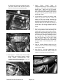
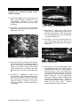
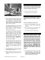
INSTRUCTIONS
Kit Number RJ10014-00
2000-2001 ROAD KING™ CRUISE CONTROL KIT
GENERAL
This cruise control kit is designed for installation
on 2000-2001 Road King Model Motorcycles.
See attached service parts list for kit contents.
WARNING
Failure to correctly install this kit may adversly
affect the function of your motorcycle. If you
are unsure of your capabilites to correctly
install this kit, or if you are lacking any of the
proper facilities, manuals, or tools you must
have this kit installed by a qualified service
technician. IMPROPER INSTALLATION
AND VEHICLE REASSEMBLY MAY
RESULT IN PROPERTY LOSS, BODILY
INJURY OR DEATH!
WARNING
It is imperative that the kill switch (on the right
hand control) operates properly.
After
installation, and before each vehicle operation,
the kill switch must be tested. In the event the
kill switch does not function correctly, do not
operate the vehicle until proper operation has
been restored. Never under any circumstance
remove right hand from controls. In the event
the cruise control or vehicle malfunctions,
immediately stop the engine with the kill
switch. Always use kill switch to shut off
motorcycle, so that you’re are familiar with it’s
position and operation. IMPROPER KILL
SWITCH OPERATION MAY RESULT IN
PROPERTY LOSS, BODILY INJURY OR
DEATH!
Service Manual Required
This instruction sheet refers the installer to the
appropriate Road King service manual for many
Document P/N: DL10714-00, rev 1.0
procedures. Therefore, you must not attempt to
install this kit without having a copy of the Road
King service manual applicable to your vehicle.
NOTE
If you do not have the correct service manual for
your motorcycle, please contact your HarleyDavidson dealer to obtain one.
Shop Supplies Required
• Materials for splicing wires (refer to
service manual for proper materials)
Specialty Tools Required
DO NOT ATTEMPT CRUISE CONTROL
INSTALLATION WITHOUT PROPER TOOLS
• Tools for splicing wires (refer to service
manual for proper tools)
• As per service manual, tools to remove
and install the following: fuel tank, hand
controls, headlight, battery, and seat.
INSTALLATION
1. Remove seat, battery, gas tank, headlight and
left-side access panel under seat (see service
manual),
and
air
cleaner
assembly.
Removing left-side bag (but not chrome
frame) will improve accessibility to install
cruise control module and route wiring
harness.
2. Replace right and left hand control with new
hand controls from kit (see service manual).
As part of replacing right hand control, install
the idle cable supplied with kit (with roll-off
switch). Use new wiring retainers included in
this kit. Make sure to adjust idle cable tension
according to the service manual.
3. See Figure 1 and Figure 2. Mount cruise
control module on outside of battery box using
the three grommets and nuts included in the
Page 1 of 4
kit (larger part of grommet towards the inside).
The Cruise Control Cable will be fed through
the hole in the frame crossmember plate.
Cruise
Control
Cable
to
5. Attach
carburetor/throttle body. Place stationary part
of cable in holder first, then snap clip onto
throttle boss. Make sure clip is secured.
Once cable is attached to carburetor/throttle
body, and cable flows smoothly (not touching
any part of cylinder), tighten barbed cable tie
and clip off excess.
6. In area above the frame and directly under
where the gas tank would be, locate the
section of the main wiring harness that
extends from the front left side of the battery,
along the top of the frame and comes to a “Y”.
Note that there are two cable ties securing it
to the frame. Cut the lower barbed cable tie
to free the main wiring harness from the
frame.
7. Feed cruise control wiring harness (CCWH)
from kit up between frame and battery box
(starting at the cruise control module location),
along main wiring harness (where you cut the
cable tie in step 6), and towards the front of
the motorcycle, entering the headlight cowl on
the rear right side. The single orange/violet
wire will be fed back over top the cruise
control module, along two other wiring
harnesses, and follow the route of the harness
that goes down to the fuse/relay block (see
Figure 2).
Figure 1. Mounting of Cruise Control Module
8. Plug the 10-place Packard connector of the
CCWH into the cruise control module making
sure it locks in place.
9. See Figure 4. Plug the orange/violet and
violet wires into the idle cable (it does not
matter which wire goes to which terminal).
Figure 2. Cruise Control Module Mounting
4. See Figure 3. Feed Cruise Control Cable
along frame and carefully between cylinder
heads towards carburetor/throttle body.
Install barbed end of barbed cable tie into hole
in frame. Do not secure cable yet.
Figure 4. Throttle Roll-off Switch
Figure 3. Cruise Control Cable Routing
Document P/N: DL10714-00, rev 1.0
Page 2 of 4
WARNING
Do not operate cruise control unless idle cable
equipped with functioning throttle roll-off
switch is installed.
10. Inside the headlight cowl, plug the gray and
black 4-place Deutsch connectors into the
corresponding connectors for the hand
controls making sure they are firmly seated
and locked.
Figure 6. Splice Wires into Main Harness.
11. See Figure 5. Secure the 1/4" ground eyelet
(black wire) under ground point in front of the
battery box (7/16" nut).
14. See Figure 6. Splice the 3 wires of the
CCWH into the corresponding colored wire of
the main wiring harness. There may be more
than one white/green wire in the main harness
- you may use either one.
15. See Figure 7. Secure 1” looming from kit over
main wiring harness with four cable ties so
that it covers and protects main wire harness
and splices.
Figure 5. Ground Terminal Location
12. Secure the CCWH to the main wiring harness
with included cable ties. Replace the cable tie
that you cut in step 4 with a barbed cable tie
(same as tie used to secure cruise control
cable) included in the kit. Replace any other
cable ties that you cut with ties included in the
kit.
13. See Figure 6. *CAREFULLY* make a 4" slit
in the protective vinyl tubing between the two
cable ties you located in step 6, near where
the 3 wires exit the CCWH, so that the wires
inside are exposed. DO NOT cut into any of
the wires themselves! You will be splicing into
3 wires here.
Document P/N: DL10714-00, rev 1.0
Figure 7. Protect Splices
16. See Figure 8. At the fuse/relay block, splice
the orange/violet wire of the CCWH into the
orange/violet wire that runs a short distance
from the back of a fuse to the brake relay.
You may need to cut the cable tie on the main
wire harness to expose this wire and make it
easier to splice into. Trim the orange/violet
wire on the CCWH as needed. Replace cable
ties with ties included in the kit. *NOTE: the
fuse/relay block detaches from the frame to
make this step much easier.
Reinstall
fuse/relay block onto frame if removed.
Page 3 of 4
WARNING
Always connect the positive battery cable first.
If the positive cable should contact ground
with the negative cable installed, the resulting
sparks may cause a battery explosion which
could result in death or serious injury.
20. Reconnect battery, positive cable first.
21. Install seat (refer to Service Manual).
Figure 7. Splice Orange/Violet Wire at Fuse Block
17. Before reassembling removed components, a
quick check can be made to confirm cruise
unit is operational. Connect ignition switch
panel/speedometer (if removed) and reinstall
battery. Make sure Run/Stop switch is in the
"Run" position, and Cruise Control On/Off
switch is in the "On" position.
Hold Set/Resume switch to the "Set" position
while turning ignition switch to "On". The
green light next to the Set/Resume switch
should illuminate.
Release Set/Resume
switch and turn ignition off.
If the light does not illuminate, check splices
and confirm that the 10-place connector is
securely plugged into the cruise control
module, and that the 4-place and 6-place
Deutsch connectors on each hand control is
securely plugged in and locked. You may
also want to verify that no pins/sockets in
these connectors is bent or pushed back –
they are fairly durable connectors, but
sometimes this can happen.
One other cause for failure of the test is that
the roll-off switch may be closed due to an
over-tight throttle/idle cable adjustment, or
binding. Remove one of the terminals and
repeat the above test. If the light illuminates,
the idle cable roll-off switch is at fault and
needs to be further investigated before you
continue.
18. If everything checks out okay, remove the
ground terminal from the battery before
reassembling the motorcycle.
WARNING
Make sure seat is properly installed according
to procedure in service manual. Failure to
install seat properly may result in injury or
death.
Cruise Cable Adjustment and Final Test
22. Perform cruise cable adjustment. See service
manual for “Cruise Control Cable Lash
Initialization”.
23. Refer to service manual or operator’s manual
for cruise control operating instructions.
24. Verify proper function of all hand controls.
WARNING
It is imperative that the kill switch (on the right
hand control) operates properly.
After
installation, and before each vehicle operation,
the kill switch must be tested. In the event the
kill switch does not function correctly, do not
operate the vehicle until proper operation has
been restored. Never under any circumstance
remove right hand from controls. In the event
the cruise control or vehicle malfunctions,
immediately stop the engine with the kill
switch. Always use kill switch to shut off
motorcycle, so that you’re are familiar with it’s
position and operation. IMPROPER KILL
SWITCH OPERATION MAY RESULT IN
PROPERTY LOSS, BODILY INJURY OR
DEATH!
25. Test ride motorcycle and verify cruise control
19. Reinstall headlight, gas tank, left access cover
under seat and left bag according to service
manual.
Document P/N: DL10714-00, rev 1.0
Page 4 of 4
is operating properly. If cruise control acts
inappropriately immediately stop engine with
kill switch. Do not operate the vehicle until
proper operation has been restored.