1
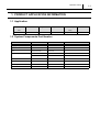
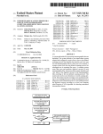
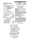
Diesel Injection Pump
SERVICE MANUAL
Common Rail System (HP3)
for MITSUBISHI L200/TRITON
4D56/4M41Engine
OPERATION
June, 2005
DENSO INTERNATIONAL THAILAND CO., LTD.
TG00400010E
© 2005 DENSO INTERNATIONAL THAILAND
All Rights Reserved. This book may not be reproduced
or copied, in whole or in part, without the written
permission of the publisher.
Table of Contents
Table of Contents
Operation Section
1. PRODUCT APPLICATION INFORMATION
1.1
Application . . . . . . . . . . . . . . . . . . . . . . . . . . . . . . . . . . . . . . . . . . . . . . . . . . . . . . . . . . . . . . . . . . . . . . . . . . . . . 1-1
1.2
System Components Part Number . . . . . . . . . . . . . . . . . . . . . . . . . . . . . . . . . . . . . . . . . . . . . . . . . . . . . . . . . . 1-1
2. OUTLINE OF SYSTEM
2.1
Common Rail System Characteristics . . . . . . . . . . . . . . . . . . . . . . . . . . . . . . . . . . . . . . . . . . . . . . . . . . . . . . . . 1-2
2.2
Features of Injection Control . . . . . . . . . . . . . . . . . . . . . . . . . . . . . . . . . . . . . . . . . . . . . . . . . . . . . . . . . . . . . . . 1-2
2.3
Comparison to the Conventional System . . . . . . . . . . . . . . . . . . . . . . . . . . . . . . . . . . . . . . . . . . . . . . . . . . . . . 1-3
2.4
Composition. . . . . . . . . . . . . . . . . . . . . . . . . . . . . . . . . . . . . . . . . . . . . . . . . . . . . . . . . . . . . . . . . . . . . . . . . . . . 1-3
2.5
Operation. . . . . . . . . . . . . . . . . . . . . . . . . . . . . . . . . . . . . . . . . . . . . . . . . . . . . . . . . . . . . . . . . . . . . . . . . . . . . . 1-4
2.6
Fuel System. . . . . . . . . . . . . . . . . . . . . . . . . . . . . . . . . . . . . . . . . . . . . . . . . . . . . . . . . . . . . . . . . . . . . . . . . . . . 1-4
2.7
Control System . . . . . . . . . . . . . . . . . . . . . . . . . . . . . . . . . . . . . . . . . . . . . . . . . . . . . . . . . . . . . . . . . . . . . . . . . 1-4
3. SUPPLY PUMP
3.1
Outline . . . . . . . . . . . . . . . . . . . . . . . . . . . . . . . . . . . . . . . . . . . . . . . . . . . . . . . . . . . . . . . . . . . . . . . . . . . . . . . . 1-6
3.2
Exterior View Diagram. . . . . . . . . . . . . . . . . . . . . . . . . . . . . . . . . . . . . . . . . . . . . . . . . . . . . . . . . . . . . . . . . . . . 1-7
3.3
Supply Pump Internal Fuel Flow . . . . . . . . . . . . . . . . . . . . . . . . . . . . . . . . . . . . . . . . . . . . . . . . . . . . . . . . . . . . 1-7
3.4
Construction of Supply Pump . . . . . . . . . . . . . . . . . . . . . . . . . . . . . . . . . . . . . . . . . . . . . . . . . . . . . . . . . . . . . . 1-8
3.5
Operation of the Supply Pump . . . . . . . . . . . . . . . . . . . . . . . . . . . . . . . . . . . . . . . . . . . . . . . . . . . . . . . . . . . . . 1-9
4. SUPPLY PUMP COMPONENT PARTS
4.1
Feed Pump . . . . . . . . . . . . . . . . . . . . . . . . . . . . . . . . . . . . . . . . . . . . . . . . . . . . . . . . . . . . . . . . . . . . . . . . . . . 1-11
4.2
SCV ( Suction Control Valve ) . . . . . . . . . . . . . . . . . . . . . . . . . . . . . . . . . . . . . . . . . . . . . . . . . . . . . . . . . . . . . 1-11
4.3
Fuel Temperature Sensor . . . . . . . . . . . . . . . . . . . . . . . . . . . . . . . . . . . . . . . . . . . . . . . . . . . . . . . . . . . . . . . . 1-13
5. RAIL
5.1
Outline . . . . . . . . . . . . . . . . . . . . . . . . . . . . . . . . . . . . . . . . . . . . . . . . . . . . . . . . . . . . . . . . . . . . . . . . . . . . . . . 1-14
6. RAIL COMPONENTS PARTS
6.1
Rail Pressure Sensor (Pc Sensor). . . . . . . . . . . . . . . . . . . . . . . . . . . . . . . . . . . . . . . . . . . . . . . . . . . . . . . . . . 1-15
6.2
Pressure limiter . . . . . . . . . . . . . . . . . . . . . . . . . . . . . . . . . . . . . . . . . . . . . . . . . . . . . . . . . . . . . . . . . . . . . . . . 1-15
7. INJECTOR (G2 TYPE)
7.1
Outline . . . . . . . . . . . . . . . . . . . . . . . . . . . . . . . . . . . . . . . . . . . . . . . . . . . . . . . . . . . . . . . . . . . . . . . . . . . . . . . 1-16
7.2
Characteristics. . . . . . . . . . . . . . . . . . . . . . . . . . . . . . . . . . . . . . . . . . . . . . . . . . . . . . . . . . . . . . . . . . . . . . . . . 1-16
7.3
Exterior View Diagram. . . . . . . . . . . . . . . . . . . . . . . . . . . . . . . . . . . . . . . . . . . . . . . . . . . . . . . . . . . . . . . . . . . 1-17
7.4
Construction . . . . . . . . . . . . . . . . . . . . . . . . . . . . . . . . . . . . . . . . . . . . . . . . . . . . . . . . . . . . . . . . . . . . . . . . . . 1-18
7.5
Operation. . . . . . . . . . . . . . . . . . . . . . . . . . . . . . . . . . . . . . . . . . . . . . . . . . . . . . . . . . . . . . . . . . . . . . . . . . . . . 1-18
7.6
QR Codes . . . . . . . . . . . . . . . . . . . . . . . . . . . . . . . . . . . . . . . . . . . . . . . . . . . . . . . . . . . . . . . . . . . . . . . . . . . . 1-19
7.7
Injector Actuation Circuit . . . . . . . . . . . . . . . . . . . . . . . . . . . . . . . . . . . . . . . . . . . . . . . . . . . . . . . . . . . . . . . . . 1-21
Table of Contents
8. OPERATION OF CONTROL SYSTEM COMPONENTS
8.1
Engine Control System Diagram . . . . . . . . . . . . . . . . . . . . . . . . . . . . . . . . . . . . . . . . . . . . . . . . . . . . . . . . . . . 1-22
8.2
Engine ECU (Electronic Control Unit) . . . . . . . . . . . . . . . . . . . . . . . . . . . . . . . . . . . . . . . . . . . . . . . . . . . . . . . 1-22
8.3
Cylinder Recognition Sensor (TDC) . . . . . . . . . . . . . . . . . . . . . . . . . . . . . . . . . . . . . . . . . . . . . . . . . . . . . . . . 1-23
8.4
Turbo Pressure Sensor . . . . . . . . . . . . . . . . . . . . . . . . . . . . . . . . . . . . . . . . . . . . . . . . . . . . . . . . . . . . . . . . . . 1-23
8.5
Mass Air Flow Sensor . . . . . . . . . . . . . . . . . . . . . . . . . . . . . . . . . . . . . . . . . . . . . . . . . . . . . . . . . . . . . . . . . . . 1-24
8.6
Electronic Control Throttle . . . . . . . . . . . . . . . . . . . . . . . . . . . . . . . . . . . . . . . . . . . . . . . . . . . . . . . . . . . . . . . . 1-25
9. VARIOUS TYPES OF CONTROL
9.1
Outline . . . . . . . . . . . . . . . . . . . . . . . . . . . . . . . . . . . . . . . . . . . . . . . . . . . . . . . . . . . . . . . . . . . . . . . . . . . . . . . 1-27
9.2
Fuel Injection Rate Control Function . . . . . . . . . . . . . . . . . . . . . . . . . . . . . . . . . . . . . . . . . . . . . . . . . . . . . . . . 1-27
9.3
Fuel Injection Quantity Control Function . . . . . . . . . . . . . . . . . . . . . . . . . . . . . . . . . . . . . . . . . . . . . . . . . . . . . 1-27
9.4
Fuel Injection Timing Control Function . . . . . . . . . . . . . . . . . . . . . . . . . . . . . . . . . . . . . . . . . . . . . . . . . . . . . . 1-27
9.5
Fuel Injection Pressure Control Function (Rail Pressure Control Function) . . . . . . . . . . . . . . . . . . . . . . . . . . 1-27
10. FUEL INJECTION QUANTITY CONTROL
10.1
Outline . . . . . . . . . . . . . . . . . . . . . . . . . . . . . . . . . . . . . . . . . . . . . . . . . . . . . . . . . . . . . . . . . . . . . . . . . . . . . . . 1-28
10.2
Injection Quantity Calculation Method . . . . . . . . . . . . . . . . . . . . . . . . . . . . . . . . . . . . . . . . . . . . . . . . . . . . . . . 1-28
10.3
Set Injection Quantities . . . . . . . . . . . . . . . . . . . . . . . . . . . . . . . . . . . . . . . . . . . . . . . . . . . . . . . . . . . . . . . . . . 1-28
11. FUEL INJECTION TIMING CONTROL
11.1
Ouline . . . . . . . . . . . . . . . . . . . . . . . . . . . . . . . . . . . . . . . . . . . . . . . . . . . . . . . . . . . . . . . . . . . . . . . . . . . . . . . 1-32
11.2
Main and Pilot Injection Timing Control . . . . . . . . . . . . . . . . . . . . . . . . . . . . . . . . . . . . . . . . . . . . . . . . . . . . . . 1-32
11.3
Microinjection Quantity Learning Control. . . . . . . . . . . . . . . . . . . . . . . . . . . . . . . . . . . . . . . . . . . . . . . . . . . . . 1-33
12. FUEL INJECTION RATE CONTROL
12.1
Outline . . . . . . . . . . . . . . . . . . . . . . . . . . . . . . . . . . . . . . . . . . . . . . . . . . . . . . . . . . . . . . . . . . . . . . . . . . . . . . . 1-35
13. FUEL INJECTION PRESSURE CONTROL
13.1
Fuel Injection Pressure . . . . . . . . . . . . . . . . . . . . . . . . . . . . . . . . . . . . . . . . . . . . . . . . . . . . . . . . . . . . . . . . . . 1-36
14. DIAGNOSTIC TROUBLE CODES (DTC)
14.1
About the Codes Shown in the Table . . . . . . . . . . . . . . . . . . . . . . . . . . . . . . . . . . . . . . . . . . . . . . . . . . . . . . . 1-37
14.2
Diagnostic Trouble Code Details . . . . . . . . . . . . . . . . . . . . . . . . . . . . . . . . . . . . . . . . . . . . . . . . . . . . . . . . . . . 1-37
15. EXTERNAL WIRING DIAGRAM
15.1
Engine ECU External Wiring Diagram. . . . . . . . . . . . . . . . . . . . . . . . . . . . . . . . . . . . . . . . . . . . . . . . . . . . . . . 1-43
15.2
Engine ECU Connector Diagram. . . . . . . . . . . . . . . . . . . . . . . . . . . . . . . . . . . . . . . . . . . . . . . . . . . . . . . . . . . 1-44
Operation Section
1. PRODUCT APPLICATION INFORMATION
1.1 Application
Vehicle Manufac-
Vehicle Name
Engine Model
Specification
ture
MITSUBISHI
Destination (Vol-
Line Off Period
ume)
L200
4D56
4WD (AT)
Europe
Dec, 2005
1.2 System Components Part Number
Parts Name
DENSO P/N
Manufacturer P/N
Remarks
Supply pump
SM294000-0331
1460A001
Injector
SM095000-5600
1465A041
Rail
SM095440-0640
1465A034
Engine ECU
MA275800-4364
1860A549
For 4WD, W/O PTC
MA275800-4374
1860A550
For 4WD W PTC
Turbo pressure sensor
079800-5960
MR577031
Electronic control throttle
197920-0020
1450A033
Fuel temperature sensor
179730-0020
MR547077
Mass air flow meter
VN197400-4030
1460A001
1– 1
1– 2
Operation Section
2. OUTLINE OF SYSTEM
2.1 Common Rail System Characteristics
The common rail system uses a type of accumulation chamber called a rail to store pressurized fuel, and injectors that contain electronically controlled solenoid valves to inject the pressurized fuel into the cylinders. Because the engine ECU controls the injection
system (injection pressure, injection rate, and injection timing), the injection system is independent, and thus unaffected by the engine
speed or load. This ensures a stable injection pressure at all times, particularly in the low engine speed range, and dramatically decreases the amount of black smoke ordinarily emitted by a diesel engine during start-up and acceleration. As a result, exhaust gas emissions are cleaner and reduced, and higher power output is achieved.
2.2 Features of Injection Control
(1) Injection Pressure Control
• Enables high-pressure injection even at low engine speeds.
• Optimizes control to minimize particulate matter and NOx emissions.
(2) Injection Timing Control
• Enables finely tuned optimized control in accordance with driving conditions.
(3) Injection Rate Control
• Pilot injection control injects a small amount of fuel before the main injection.
Operation Section
2.3 Comparison to the Conventional System
In-line, VE Pump
Common Rail System
System
Pump (Governor)
Engine ECU, Injector (TWV)*1
Pump (Timer)
Engine ECU, Injector (TWV)*1
Pump
Engine ECU, Supply Pump
Distributor
Pump
Engine ECU, Rail
Injection
Dependent upon Speed and Injection Quantity
Engine ECU, Supply Pump (SCV)*2
Injection
Quantity
Control
Injection
Timing
Control
Rising
Pressure
Pressure
Control
< NOTE >
*1 : TWV: Two Way Valve
*2 : SCV: Suction Control Valve
2.4 Composition
The common rail system consists primarily of a supply pump, rail, injectors, and engine ECU.
1– 3
1– 4
Operation Section
2.5 Operation
(1) Supply Pump (HP3)
• The supply pump draws fuel from the fuel tank, and pumps the high pressure fuel to the rail. The quantity of fuel discharged from the
supply pump controls the pressure in the rail. The SCV (Suction Control Valve) in the supply pump effects this control in accordance
with commands received from the engine ECU.
(2) Rail
• The rail is mounted between the supply pump and the injector, and stores the high-pressure fuel.
(3) Injector (G2 type)
• This injector replaces the conventional injection nozzle, and achieves optimal injection by effecting control in accordance with signals
from the engine ECU. Signals from the engine ECU determine the duration and timing in which current is applied the injector. This
in turn, determines the quantity, rate and timing of the fuel that is injected from the injector.
(4) Engine ECU
• The engine ECU calculates data received from the sensors to comprehensively control the injection quantity, timing and pressure, as
well as the EGR (exhaust gas recirculation).
2.6 Fuel System
This system comprises the route through which diesel fuel flows from the fuel tank via the rail to the supply pump, and is injected
through the injector, as well as the route through which the fuel returns to the tank via the overflow pipe.
2.7 Control System
In this system, the engine ECU controls the fuel injection system in accordance with signals received from various sensors. The components of this system can be broadly divided into the following three types: (1) sensors; (2) ECU; and (3) actuators.
Operation Section
1– 5
(1) Sensors
• Detect the engine and driving conditions, and convert them into electrical signals.
(2) Engine ECU
• Performs calculations based on the electrical signals received from the sensors, and sends them to the actuators in order to achieve
optimal conditions.
(3) Actuators
• Operate in accordance with electrical signals received from the ECU. Injection system control is undertaken by electronically controlling the actuators. The injection quantity and timing are determined by controlling the duration and timing in which current is applied
to the TWV (Two-Way Valve) in the injector. Injection pressure is determined by controlling the SCV (Suction Control Valve) in the
supply pump.
1– 6
Operation Section
3. SUPPLY PUMP
3.1 Outline
The supply pump consists primarily of the pump body (eccentric cam, ring cam, and plungers), SCV (Suction Control Valve), fuel
temperature sensor, and feed pump.
The two plungers are positioned vertically on the outer ring cam for compactness.
The engine drives the supply pump at a ratio of 1:1. The supply pump has a built-in feed pump (trochoid type), and draws the fuel
from the fuel tank, sending it to the plunger chamber.
The internal camshaft drives the two plungers, and they pressurize the fuel sent to the plunger chamber and send it to the rail. The
quantity of fuel supplied to the rail is controlled by the SCV, using signals from the engine ECU. The SCV is a normally open type
(the intake valve opened during de-energization).
Operation Section
3.2 Exterior View Diagram
4D56 Engine Model
4M41 Engine Model
3.3 Supply Pump Internal Fuel Flow
The fuel that is drawn from the fuel tank passes through the route in the supply pump as illustrated, and is fed into the rail.
1– 7
1– 8
Operation Section
3.4 Construction of Supply Pump
The eccentric cam is attached to the drive shaft. The eccentric cam is connected to the ring cam.
As the drive shaft rotates, the eccentric cam rotates eccentrically, and the ring cam moves up and down while rotating.
The plunger and the suction valve are attached to the ring cam. The feed pump is connected to the rear of the drive shaft.
Operation Section
1– 9
3.5 Operation of the Supply Pump
As shown in the illustration below, the rotation of the eccentric cam causes the ring cam to push Plunger A upwards. Due to the spring
force, Plunger B is pulled in the opposite direction to Plunger A. As a result, Plunger B draws in fuel, while Plunger A pumps it to the
rail.
1– 10
Operation Section
Operation Section
1– 11
4. SUPPLY PUMP COMPONENT PARTS
4.1 Feed Pump
The trochoid type feed pump, which is integrated in the supply pump, draws fuel from the fuel tank and feeds it to the two plungers
via the fuel filter and the SCV (Suction Control Valve). The feed pump is driven by the drive shaft. With the rotation of the inner rotor,
the feed pump draws fuel from its suction port and pumps it out through the discharge port. This is done in accordance with the space
that increases and decreases with the movement of the outer and inner rotors.
4.2 SCV ( Suction Control Valve )
A linear solenoid type valve has been adopted. The ECU controls the duty ratio (the duration in which current is applied to the SCV),
in order to control the quantity of fuel that is supplied to the high-pressure plunger.
Because only the quantity of fuel that is required for achieving the target rail pressure is drawn in, the actuating load of the supply
pump decreases.
When current flows to the SCV, variable electromotive force is created in accordance with the duty ratio, moving the cylinder (integrated with the armature) to the left side, and changing the opening of the fuel passage to regulate the fuel quantity.
With the SCV OFF, the return spring contracts, completely opening the fuel passage and supplying fuel to the plungers. (Full quantity
intake and full quantity discharge = normally open)
When the SCV is ON, the force of the return spring moves the cylinder to the left, closing the fuel passage (normally open).
By turning the SCV ON/OFF, fuel is supplied in an amount corresponding to the actuation duty ratio, and fuel is discharged by the
plungers.
1– 12
Operation Section
(1) SCV Opening Small (Duty ON time long - Refer to the "Relationship Between Actuation
Signal and Current" Diagram.)
• When the opening of the SCV is small, the fuel suction area is kept small, which decreases the transferable fuel volume.
(2) SCV Opening Large (Duty ON time short - Refer to the "Relationship Between Actuation
Signal and Current" Diagram.)
• When the opening of the SCV is large, the fuel suction area is kept large, which increases the transferable fuel volume.
Operation Section
1– 13
(3) Diagram of Relationship Between Actuation Signal and Current (Magneto motive Force)
4.3 Fuel Temperature Sensor
Detects the fuel temperature and sends a corresponding signal to the engine ECU. Based on this information, the engine ECU calculates the injection volume correction that is appropriate for the fuel temperature.
1– 14
Operation Section
5. RAIL
5.1 Outline
Stores pressurized fuel (25 to 180 MPa) that has been delivered from the supply pump and distributes the fuel to each cylinder injector.
A rail pressure sensor and a pressure limiter valve are adopted in the rail.
The rail pressure sensor (Pc sensor) detects fuel pressure in the rail and sends a signal to the engine ECU, and the pressure limiter
controls the excess pressure. This ensures optimum combustion and reduces combustion noise.
Operation Section
1– 15
6. RAIL COMPONENTS PARTS
6.1 Rail Pressure Sensor (Pc Sensor)
The pressure sensor detects the fuel pressure of the rail, and sends a signal to the engine ECU. The sensor is made from a semiconductor that uses the Piezo resistive effect to detect changes in electrical resistance based on the pressure applied to the elemental silicon. In comparison to the old model, this sensor is compatible with high pressure.
6.2 Pressure limiter
The pressure limiter releases pressure when the internal pressure of the rail becomes abnormally high. The pressure limiter opens when
internal pressure reaches 221MPa (2254 kg/cm2) and closes when rail pressure reaches a given set pressure. Fuel released from the
pressure limiter is returned to the fuel tank.
1– 16
Operation Section
7. INJECTOR (G2 TYPE)
7.1 Outline
The injectors inject the high-pressure fuel from the rail into the combustion chambers at the optimum injection timing, rate, and spray
condition, in accordance with commands received from the ECU.
7.2 Characteristics
A compact, energy-saving solenoid-control type TWV (Two-Way Valve) injector has been adopted.
QR codes displaying various injector characteristics and the ID codes showing these in numeric form (30 alphanumeric figures) are
engraved on the injector head. The common rail system optimizes injection volume control using this information. When an injector
is newly installed in a vehicle, it is necessary to enter the ID codes in the engine ECU using the MITSUBISHI diagnosis tool (MUT
III).
Operation Section
7.3 Exterior View Diagram
1– 17
1– 18
Operation Section
7.4 Construction
7.5 Operation
The TWV (Two-Way Valve) solenoid valve opens and closes the outlet orifice to control both the pressure in the control chamber, and
the start and end of injection.
(1) Non injection
• When no current is supplied to the solenoid, the spring force is stronger than the hydraulic pressure in the control chamber. Thus, the
Operation Section
1– 19
solenoid valve is pushed downward, effectively closing the outlet orifice. For this reason, the hydraulic pressure that is applied to the
command piston causes the nozzle spring to compress. This closes the nozzle needle, and as a result, fuel is not injected.
(2) Injection
• When current is initially applied to the solenoid, the attraction force of the solenoid pulls the solenoid valve up, effectively opening
the outlet orifice and allowing fuel to flow out of the control chamber. After the fuel flows out, the pressure in the control chamber
decreases, pulling the command piston up. This causes the nozzle needle to rise and the injection to start.
• The fuel that flows past the outlet orifice flows to the leak pipe and below the command piston. The fuel that flows below the piston
lifts the piston needle upward, which helps improve the nozzle's opening and closing response.
(3) End of Injection
• When current continues to be applied to the solenoid, the nozzle reaches its maximum lift, where the injection rate is also at the maximum level. When current to the solenoid is turned OFF, the solenoid valve falls, causing the nozzle needle to close immediately and
the injection to stop.
7.6 QR Codes
Conventionally the whole injector Assy was replaced during injector replacement, but QR (Quick Response) codes have been adopted
to improve injector quantity precision.
1– 20
Operation Section
4D56 Engine Model
4M41 Engine Model
QR codes have resulted in a substantial increase in the number of fuel injection quantity correction points, greatly improving precision.
The characteristics of the engine cylinders have been further unified, contributing to improvements in combustion efficiency, reductions in exhaust gas emissions and so on.
(1) Repair Procedure
• When replacing injectors with QR codes, or the engine ECU, it is necessary to record the ID codes in the ECU. (If the ID codes for
the installed injectors are not registered correctly, engine failure such as rough idling and noise will result). The ID codes will be registered in the ECU at a MITSUBISHI dealer using approved MITSUBISHI tools.
Operation Section
1– 21
Replacing the Injector
Replacing the Engine ECU
7.7 Injector Actuation Circuit
In order to improve injector responsiveness, the actuation voltage has been changed to high voltage, speeding up both solenoid magnetization and the response of the TWV. The EDU or the charge circuit in the ECU raises the respective battery voltage to approximately 85V, which is supplied to the injector by signal from the ECU to actuate the injector.
1– 22
Operation Section
8. OPERATION OF CONTROL SYSTEM COMPONENTS
8.1 Engine Control System Diagram
8.2 Engine ECU (Electronic Control Unit)
This is the command center that controls the fuel injection system and the engine operation in general.
Operation Section
1– 23
8.3 Cylinder Recognition Sensor (TDC)
Outputs a cylinder identification signal. The sensor outputs 5 pulses for every two revolutions (720°CA) of the engine.
8.4 Turbo Pressure Sensor
This is a type of semi-conductor pressure sensor. It utilizes the characteristics of the electrical resistance changes that occur when the
pressure applied to a silicon crystal changes. Because a single sensor is used to measure both turbo pressure and atmospheric pressure,
a VSV is used to alternate between atmospheric and turbo pressure measurement.
1– 24
Operation Section
(1) Atmospheric Pressure Measurement Conditions
• The VSV turns ON for 150msec to detect the atmospheric pressure when one of the conditions below is present:
• Engine speed = 0rpm
• Starter is ON
• Idle is stable
(2) Turbo Pressure Measurement Conditions
• The VSV turns OFF to detect the turbo pressure if the atmospheric pressure measurement conditions are absent.
8.5 Mass Air Flow Sensor
This air flow meter, which is a plug-in type, allows a portion of the intake air to flow through the detection area. By directly measuring
the mass and the flow rate of the intake air, the detection precision has been improved and the intake air resistance has been reduced.
This mass air flow meter has a built-in intake air temperature sensor.
Operation Section
1– 25
8.6 Electronic Control Throttle
(1) Outline
• The suctioning of air is stopped through interlocking the intake throttle with the key switch in order to reduce engine vibration when
the vehicle is turned off.
1– 26
Operation Section
(2) Operation
Operation Section
1– 27
9. VARIOUS TYPES OF CONTROL
9.1 Outline
This system effects fuel injection quantity and injection timing control more appropriately than the mechanical governor and timer
used in the conventional injection pump. The engine ECU performs the necessary calculations in accordance with the sensors installed
on the engine and the vehicle. It then controls the timing and duration of time in which current is applied to the injectors, in order to
realize both optimal injection and injection timing.
9.2 Fuel Injection Rate Control Function
Pilot injection control injects a small amount of fuel before the main injection.
9.3 Fuel Injection Quantity Control Function
The fuel injection quantity control function replaces the conventional governor function. It controls the fuel injection to an optimal
injection quantity based on the engine speed and accelerator position signals.
9.4 Fuel Injection Timing Control Function
The fuel injection timing control function replaces the conventional timer function. It controls the injection to an optimal timing based
on the engine speed and the injection quantity.
9.5 Fuel Injection Pressure Control Function (Rail Pressure Control Function)
The fuel injection pressure control function (rail pressure control function) controls the discharge volume of the pump by measuring
the fuel pressure at the rail pressure sensor and feeding it back to the ECU. It effects pressure feedback control so that the discharge
volume matches the optimal (command) value set in accordance with the engine speed and the injection quantity.
1– 28
Operation Section
10. FUEL INJECTION QUANTITY CONTROL
10.1 Outline
This control determines the fuel injection quantity by adding coolant temperature, fuel temperature, intake air temperature, and intake
air pressure corrections to the basic injection quantity. The engine ECU calculates the basic injection quantity based on the engine
operating conditions and driving conditions.
10.2 Injection Quantity Calculation Method
The calculation consists of a comparison of the following two values: 1. The basic injection quantity that is obtained from the governor
pattern, which is calculated from the accelerator position and the engine speed. 2. The injection quantity obtained by adding various
types of corrections to the maximum injection quantity obtained from the engine speed. The lesser of the two injection quantities is
used as the basis for the final injection quantity.
10.3 Set Injection Quantities
(1) Basic Injection Quantity
• This quantity is determined by the engine speed and the accelerator opening. With the engine speed constant, if the accelerator opening
increases, the injection quantity increases; with the accelerator opening constant, if the engine speed rises, the injection quantity decreases.
Operation Section
1– 29
(2) Maximum Injection Quantity
• This is determined based on the basic maximum injection quantity determined by the engine speed, and the added corrections for intake air pressure.
(3) Starting Injection Quantity
• When the starter switch is turned ON, the injection quantity is calculated in accordance with the starting base injection volume. The
base injection quantity and the inclination of the quantity increase/decrease change in accordance with the water temperature and the
engine speed.
Injection quantity
Water temperature
Base injection
quantity
Starter ON time
STA/ON
Start
QD0805E
(4) Idle Speed Control (ISC) System
• This system controls the idle speed by regulating the injection quantity in order to match the actual speed to the target speed calculated
by the engine ECU.
1– 30
Operation Section
• The target speed varies, depending on the ON/OFF state of the air conditioner and the coolant temperature.
(5) Idle Vibration Reduction Control
• In order to reduce vibration during idling, the angular (time difference between A and B [C and D]) speed of each cylinder is detected
using the speed pulse signal to control the injection quantity of each cylinder. As a result crank angle speed becomes more uniform
and smoother engine operation is achieved.
Operation Section
Speed Pulse
Control Diagram
1– 31
1– 32
Operation Section
11. FUEL INJECTION TIMING CONTROL
11.1 Ouline
Fuel injection timing is controlled by varying the timing in which current is applied to the injectors.
11.2 Main and Pilot Injection Timing Control
(1) Main Injection Timing
• The engine ECU calculates the basic injection timing based on the engine speed and the final injection quantity, and adds various types
of corrections in order to determine the optimal main injection timing.
(2) Pilot Injection Timing (Pilot Interval)
• Pilot injection timing is controlled by adding a pilot interval to the main injection timing. The pilot interval is calculated based on the
final injection quantity, engine speed, coolant temperature, ambient temperature, and atmospheric pressure (map correction). The pilot
interval at the time the engine is started is calculated from the coolant temperature and engine speed.
Operation Section
1– 33
(3) Injection Timing Calculation Method
11.3 Microinjection Quantity Learning Control
(1) Outline
• Quantity learning control is used in every vehicle engine (injector) to preserve the accuracy of quantity (specifically, pilot injection
quantity.)
This type of control is first performed when shipped from the factory (L/O), and later is automatically performed every time the vehicle
runs a set distance (for details, see item "A".) Because of quantity learning control, the accuracy of each injector can be preserved not
only initially, but also as deterioration in injection occurs over time. As a result of this learning, correction values are recorded in the
ECU. During normal driving operations, this correction value is used to make modifications to injection commands, resulting in accurate microinjection.
(2) Learning Operations
• For every two no load, idle instability conditions established (See chart "A" below) quantity learning takes place.
In addition, it is also possible to perform quantity learning control manually as a diagnostic tool.
1– 34
Operation Section
(3) Operational Outline
• Learning control sends ISC (target speed correction quantity) and FCCB (cylinder-to-cylinder correction quantity) feedback based on
engine speed to apply injection control. The correction quantity is added to each cylinder based on ISC and FCCB correction information. The corrected injection quantity is then calculated.
Through the use of quantity learning control, injection is divided into 5 injections. In this state, the value for ISC and FCCB corrected
injection quantity that has been divided into five injections is calculated as the "learning value".
Operation Section
1– 35
12. FUEL INJECTION RATE CONTROL
12.1 Outline
While the injection rate increases with the adoption of high-pressure fuel injection, the ignition lag, which is the delay from the time
fuel is injected to the beginning of combustion, cannot be shortened to less than a certain value. As a result, the quantity of fuel that
is injected until main ignition occurs increases, resulting in an explosive combustion at the time of main ignition. This increases both
NOx and noise. For this reason, pilot injection is provided to minimize the initial ignition rate, prevent the explosive first-stage combustion, and reduce noise and NOx.
1– 36
Operation Section
13. FUEL INJECTION PRESSURE CONTROL
13.1 Fuel Injection Pressure
The engine ECU determines the fuel injection pressure based on the final injection quantity and the engine speed. The fuel injection
pressure at the time the engine is started is calculated from the coolant temperature and engine speed.
Operation Section
1– 37
14. DIAGNOSTIC TROUBLE CODES (DTC)
14.1 About the Codes Shown in the Table
The "SAE" diagnostic trouble code indicates the code that is output through the use of the STT (WDS). (SAE: Society of Automotive
Engineers)
14.2 Diagnostic Trouble Code Details
The DTC chart below is common to the 4D56/4M41 model. However, DTC number "P1210" is only for use with the 4D56 2WD model engine.
DTC
Diagnostic Item
Diagnostic Classifica-
Number
Malfunctioning Part
tion
Light
ON
(SAE)
P0016
Speed-G
phase
gap Pulse system malfunc- Crankshaft position sen-
malfunction
tion
Yes
sor, cylinder recognition
sensor
P0072
Intake manifold tem- Open circuit detection Intake temperature sensor
perature sensor - low
(+B
short,
No
ground
short, open)
P0073
Intake manifold tem- Open circuit detection Intake temperature sensor
perature sensor - high
(+B
short,
No
ground
short, open)
P0088
P0089
Rail
high
pressure Fuel pressure control Injector
abnormality
system abnormality
SCV stuck diagnosis
Fuel pressure control Supply pump
Yes
Yes
system abnormality
P0093
Fuel leak
Fuel leak
P0102
Airflow sensor - low
Open circuit detection Air Flow Sensor
(+B
Fuel piping
short,
Yes
No
ground
short, open)
P0103
Airflow sensor - high
Open circuit detection Air Flow Sensor
(+B
short,
No
ground
short, open)
P0106
Turbo pressure sensor Sensor
characteristic
characteristic Turbo pressure sensor
Yes
abnor- abnormality
mality
P0107
Turbo pressure sensor - Open circuit detection Turbo pressure sensor
low
(+B
short,
Yes
ground
short, open)
P0108
Turbo pressure sensor - Open circuit detection
high
(+B
short,
short, open)
ground Turbo pressure sensor
Yes
Remarks
Operation Section
1– 38
DTC
Diagnostic Item
Diagnostic Classifica-
Number
Malfunctioning Part
tion
Light
ON
(SAE)
P0112
Intake
temperature Open circuit detection Intake temperature sen-
sensor - low
(+B
short,
Yes
ground sor (AFS)
short, open)
P0113
Intake
temperature Open circuit detection Intake temperature sen-
sensor - high
(+B
short,
Yes
ground sor (AFS)
short, open)
P0117
Coolant
temperature Open circuit detection Coolant temperature
sensor - low
(+B
short,
Yes
ground sensor
short, open)
P0118
Coolant
temperature Open circuit detection Coolant temperature
sensor - high
(+B
short,
Yes
ground sensor
short, open)
P0122
Electronic
throttle - low
control Open circuit detection Electronic control throttle
(+B
short,
Yes
ground
short, open)
P0123
Intake valve sensor - Open circuit detection Electronic control throttle
high
(+B
short,
Yes
ground
short, open)
P0182
Fuel temperature sen- Open circuit detection Supply Pump
sor - low
(+B
short,
Yes
ground
short, open)
P0183
Fuel temperature sen- Open circuit detection Supply Pump
sor - high
(+B
short,
Yes
ground
short, open)
P0191
Rail pressure sensor Sensor
characteristic
characteristic Rail
Yes
abnor- abnormality
mality
P0192
Rail pressure sensor Open circuit detection Rail
(time) low
(+B
short,
Yes
ground
short, open)
P0193
Rail pressure sensor Open circuit detection Rail
(time) high
(+B
short,
Yes
ground
short, open)
P0201
TWV 1 (No.1 cylin- Injector
actuation Injector
Yes
actuation Injector
Yes
actuation Injector
Yes
actuation Injector
Yes
der) actuation system abnormality
open circuit
P0202
TWV 4 (No.2 cylin- Injector
der) actuation system abnormality
open circui
P0203
TWV 2 (No.3 cylin- Injector
der) actuation system abnormality
open circuit
P0204
TWV 3 (No.4 cylin- Injector
der) actuation system abnormality
open circuit
Remarks
Operation Section
DTC
Diagnostic Item
Diagnostic Classifica-
Number
Malfunctioning Part
tion
Light
ON
(SAE)
P0219
Engine overrun abnor- Engine abnormality
Engine
Yes
Engine
Yes
Injector function (non - Injector actuation abnor Injector
Yes
mality
P0234
High boost abnormal- Engine abnormality
ity diagnosis
P0301
injection) 1
P0302
malily
Injector function (non - Injector actuation abnor Injector
injection) 2
P0303
Injector function (non - Injector actuation abnor Injector
injection) 3
P0304
Injector function (non - Injector actuation abnor Injector
P0340
No speed pulse input
Pulse system malfunc- Crankshaft position sen-
Abnormal speed pulse Pulse system malfunc- Crankshaft position sennumber
tio
No G pulse input
Pulse system malfunc- Cylinder recognition sen-
Yes
sor
Yes
sor
recognition Pulse system malfunc- Cylinder recognition sen-
Cylinder
Yes
sor
tion
P0341
Yes
malily
tion
P0336
Yes
malily
injection) 4
P0335
Yes
malily
sensor pulse number tion
Yes
sor
abnormality
P0405
EGR lift sensor - low
Open circuit detection EGR valve
(+B
short,
No
ground
short, open)
P0406
EGR lift sensor - high
Open circuit detection EGR valve
(+B
short,
No
ground
short, open)
P0502
P0513
Vehicle speed
Pulse system malfunc- Vehicle speed sensor
abnormality - low
tion
Immobilizer authenti- Network
Network
Yes
Yes
catuin error
P0551
P0603
Power Steering Switch Power Steering Switch Power Steering Switch
ON malfuncion
malfuncion
EEPROM abnormality
Engine ECU internal Engine ECU
Yes
Yes
circuit memory device
P0604
RAM abnormality
P0605
Engine
ECU
Engine ECU
Engine ECU
Engine ECU
Engine ECU
CPU Engine ECU
Engine ECU
Yes
Engine ECU
Yes
flash-
ROM abnormality
P0606
Engine
ECU
Yes
Yes
abnormality (main IC
abnormality)
P0607
Engine ECU abnor- Engine ECU
mality (monitoring IC
abnormality)
Remarks
1– 39
Operation Section
1– 40
DTC
Diagnostic Item
Diagnostic Classifica-
Number
Malfunctioning Part
tion
Light
Remarks
ON
(SAE)
P0628
P0629
SCV actuation system Fuel pressure control
abnormality
system abnormality
SCV +B short
Fuel pressure control
Supply pump
Yes
Supply pump
Yes
system abnormality
P0630
VIN not registered in Engine
Engine ECU
ECU
write Engine
defect
ECU
(VIN
Yes
rewrite)
VIN stands for “Vehicle Identification Number”. If this DTC code
is detected, rewrite the
VIN to the Engine
ECU. This does not
mean that engine ECU
is malfunctioning. Do
not replace the engine
ECU
P0638
Intake throttle valve Actuator malfunction
Electronic control throttle
Yes
stuck
P0642
Sensor - voltage 1 low
Engine ECU
Engine ECU
Yes
P0643
Sensor - voltage 1 high Engine ECU
Engine ECU
Yes
P0652
Sensor - voltage 2 low
Engine ECU
Engine ECU
Yes
P0653
Sensor - voltage 2 high Engine ECU
Engine ECU
Yes
P1203
Low charge
Engine ECU
Engine ECU
Yes
P1204
Over charge
Engine ECU
Engine ECU
Yes
P1272
P/L open valve abnor- Fuel pressure control
Rail
Yes
Supply pump
Yes
mality
P1273
system abnormality
Single pump abnor- Fuel pressure control
mality diagnosis
system abnormality
In the event that the
vehicle runs out of gas,
"P1273"
may
be
detected
when
the
vehicle is restarted.
When "P1273" is displayed, the user should
verify whether or not
there is gas in the vehicle.
Do not replace the
pump assy. if it has
been verified that the
vehicle has run out of
gas. Remove the air
from the fuel, and erase
the code using the
MITSUBISHI MUT III
diagnosis tool.
P1274
Pump protective fill Fuel pressure control
plug
system abnormality
Supply pump
Yes
Operation Section
DTC
Diagnostic Item
Diagnostic Classifica-
Number
Malfunctioning Part
tion
Light
ON
(SAE)
P1275
P1625
Pump
exchange
fill Fuel pressure control
Supply pump
Yes
Engine ECU
Engine ECU
Yes
QR data failure to Engine ECU
Engine ECU
Yes
Electronic control throttle
Yes
sensor-1 Open circuit detection Accelerator position sen-
Yes
plug
system abnormality
QR data
abnormality
P1626
write to disc malfunction
P2118
DC motor over current Actuator malfunction
abnormality
P2122
Accelerator
low
(+B
short,
ground sor
short, open)
P2123
sensor-1 Open circuit detection Accelerator position sen-
Accelerator
high final
(+B
short,
Yes
ground sor
short, open)
P2124
sensor-1 Open circuit detection Accelerator position sen-
Accelerator
high
(+B
short,
No
ground sor
short, open)
P2127
sensor-2 Open circuit detection Accelerator position sen-
Accelerator
low
(+B
short,
Yes
ground sor
short, open)
P2138
Accelerator sensor - Open circuit detection Accelerator position senduplicate malfunction (+B
short,
ground sor
short, open)
high
Accelerator sensor - Open circuit detection Accelerator Position Senduplicate malfunction (+B
ACCP
characteristic Sensor
abnormality
Common
characteristic Accelerator Position Sen-
1
system Injector
system
Yes
sor
actuation Injector , Wire harness or
abnormality
COM1 TWV actua- Injector
tion
Yes
ground sor
abnormality
open circuit
P2147
short,
short, open)
low
P2146
Yes
Yes
Engine ECU
actuation Injector, Wire harness or
ground abnormality
Yes
Engine ECU
short
P2148
COM1 TWV actua- Injector
tion system +B short
P2149
Common
2
open circuit
P2228
actuation Injector, Wire harness or
abnormality
system Injector
Engine ECU
actuation
Yes
abnormality
Atmospheric pressure Open circuit detection Engine ECU
sensor - low
Yes
(+B
short,
Yes
ground
short, open)
P2229
Atmospheric pressure Open circuit detection Engine ECU
sensor - high
(+B
short,
short, open)
ground
Yes
Remarks
1– 41
Operation Section
1– 42
DTC
Diagnostic Item
Diagnostic Classifica-
Number
Malfunctioning Part
tion
Light
ON
(SAE)
P2413
EGR feedback abnor- Actuator malfunction
EGR valve
No
mality
UD073
CAN bus OFF error
Network
Network
No
UD101
CAN time out flag Network
Network
No
Network
No
Network
No
Network
No
Network
No
(trans)
UD102
CAN time out flag Network
(ESP)
UD109
CAN time out flag Network
(ETACS)
UD117
CAN time out flag Network
(immobilizer)
UD190
CAN communication
Network
Remarks
Operation Section
15. EXTERNAL WIRING DIAGRAM
15.1 Engine ECU External Wiring Diagram
The wiring diagram below is common to the 4D56/4M41 model.
1– 43
Operation Section
1– 44
15.2 Engine ECU Connector Diagram
The connector diagram and terminal below are common to the 4D56/4M41 model.
Terminal Connections (1)
No.
Pin Symbol
Signal Name
No.
Pin Symbol
Signal Name
A01
P-GND
Power Ground
A11
—
—
A02
—
—
A12
A/C1 SW
Air Condition 1 Switch
A03
P-GND
Power Ground
A13
—
—
A04
COMMON 1
INJ#1/#4 BATT.
A14
—
—
A05
COMMON 1
INJ#2/#3 BATT.
A15
—
—
A06
—
—
A16
W
Engine Warning Light
A07
EGR-
EGR-DC Motor (-)
A17
—
—
A08
EGR+
EGR-DC Motor (+)
A18
—
—
A09
—
—
A19
—
—
A10
SCV+
Suction Control Valve
A20
—
—
Operation Section
1– 45
Terminal Connections (2)
No.
Pin Symbol
Signal Name
No.
Pin Symbol
Signal Name
A56
—
—
A57
—
—
A58
—
—
A59
—
—
A60
—
—
A21
TW4
Injection 4 Drive (# 2 Cylinder)
A22
A23
TWV2
Injection 2 Drive (#3 Cylinder)
A24
A25
—
—
A61
—
—
A26
A/C R
Air Conditioning Relay
A62
—
—
A27
C FAN R
FAN Relay
A63
A-VCC5
Rail Pressure Sensor Source
A28
—
—
A64
A-VCC6
Turbo Pressure Sensor Source (5V)
A29
SCV-
Suction Control Valve
A65
NE-
Crankshaft Position Sensor Ground
A30
—
—
A66
G-
Cylinder Recognition Sensor Ground
A31
—
—
A67
—
—
A32
—
—
A68
PFUEL RTN
Rail Pressure Sensor Earth
A33
—
—
A69
THF RTN
Air Temperature Sensor, Fuel Temperature Sensor Earth
A34
—
—
A70
THW RTN
Coolant Temperature Sensor Earth
A35
—
—
A71
BOOST RTN
Turbo Pressure Sensor
A36
—
—
A72
EGR Lift RTN
EGR Position Sensor Earth
A37
Glow R
Glow Plug Relay
A73
AMF-RTN
Airflow Sensor Earth
A38
Glow L
Glow Light
A74
EXT-A-RTN
Air Temperature Sensor Earth
(W/FAS)
A39
—
—
A75
—
—
A40
TWV3
Injection 3 Drive (#4 Cylinder)
A76
—
—
A41
TWV3
Injection 3 Drive (#4 Cylinder)
A77
—
—
A42
TWV1
Injection 1 Drive (#1 Cylinder)
A78
—
—
A43
TWV1
Injection 1 Drive (#1 Cylinder)
A79
THA
Air Temperature Sensor
A44
A-VCC3
Crankshaft Position Sensor BATT
A80
—
—
A45
A-VCC4
Cylinder Recognition Sensor BATT
A81
—
—
A46
NE+
Crankshaft Position Sensor
B01
A-VCC 1
Accelerator Position Sensor (Main)
Source
A47
G+
Cylinder Recognition Sensor
B02
APS 1
Accelerator Position Sensor (Main)
A48
PFUEL 1
Rail Pressure Sensor (Pc Sensor)
B03
APS 1 GND
Accelerator Position Sensor (Main)
Earth
A49
—
—
B04
—
—
A50
THF
Fuel Temperature Sensor
B05
ETCP-M
Electronic Throttle Control (Main)
A51
THW
Coolant Temperature Sensor
B06
CAN1-L
CAN L (W/Resister)
A52
BOOST
Turbo Pressure Sensor
B07
—
—
A53
EGR LIFT
EGR Position Sensor
B08
—
—
A54
AMF
Airflow Sensor
B09
A-VCC 2
Accelerator Position Sensor (Sub)
Source
A55
EXT-A-TMP
Air Temperature Sensor (W/AFS)
B10
APS 2
Accelerator Position Sensor (Sub)
Operation Section
1– 46
Terminal Connections (3)
No.
B11
Pin Symbol
APS 2 GND
Signal Name
No.
Accelerator Position Sensor (Sub) B26
Pin Symbol
Signal Name
IG-SW
Ignition Switch
Earth
B12
—
—
B27
—
—
B13
—
—
B28
—
—
B14
CAN1-H
CAN H (W/Resister)
B29
—
—
B15
—
—
B30
PS-SW
Power Steering Switch
B16
SPD
Vehicle Speed Sensor
B31
—
—
B17
—
—
B32
—
—
B18
STA-SW
Starter Switch
B33
C-GND
SIG Ground
B19
MT 1ST SW
1st Shift Switch
B34
—
—
B20
MT REV SW
Reverse Shift Switch
B35
ETC+
Electronic Throttle Control Motor (+)
B21
—
—
B36
—
—
B22
—
—
B37
ETC-
Electronic Throttle Control Motor (-)
B23
—
—
B38
+BP
Battery
B24
M-REL
—
—
BATT.
Battery (Back-up, W/Monitor)
Control
(ECCS)
Relay
(W/ B39
DIODE)
B25
TACHO
Tacho meter
B40
Published
: June, 2005
Edited and published by:
DENSO INTERNATIONAL THAILAND
Field Technical Service Department
369 Moo 3 Teparak Rd. Muang Samutprakarn
Thailand