1
Service Manual
FILE No.
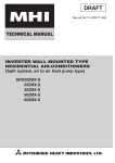
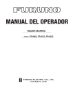
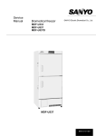
Ultra-Low Temperature Freezer
MDF-U33V
MDF-U32V(N)
SANYO Electric Co., Ltd.
Biomedical Business Division
RoHS
This product does not contain any hazardous substances prohibited by the RoHS Directive.
(You will find ‘RSF’ mark near the rating plate on the RoHS compliant product.)
WARNING
* You are requested to use RoHS compliant parts for maintenance or repair.
* You are requested to use lead-free solder.
Effective models
This service manual is effective following models.
Model name
MDF-U33V
MDF-U32V(N)
Product code
823 003 51
823 003 52
823 003 53
823 003 54
823 003 55
Voltage and Frequency
115V
60Hz
220V
50Hz
220V
60Hz
230/240V
50Hz
220V
50Hz
Contents
㩷㩷㩷㩷㩷㩷㩷㩷㩷㩷㩷㩷㩷㩷㩷㩷㩷㩷㩷㩷㩷㩷㩷㩷㩷㩷㩷㩷㩷㩷㩷㩷㩷㩷㩷㩷㩷㩷㩷㩷㩷㩷㩷㩷㩷㩷㩷㩷㩷㩷㩷㩷㩷
Page
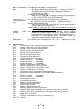
Warming up operation at low ambient temperature
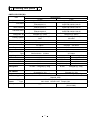
Specifications
-----------------------
1
--------------------------------------------------------------------------
2
- Structural specifications
- Control specifications
- Performance specifications
Dimensions
--------------------------------------------------------------------------
5
-------------------------------------------------------------------------------
6
Cooling unit parts
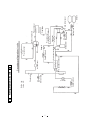
Refrigeration circuits
-----------------------------------------------------------------
7
Components on PCB
-----------------------------------------------------------------
8
--------------------------------------------------------------------------
9
Electrical parts
Specifications of sensor
-------------------------------------------------------------
10
Connections on PCB
-----------------------------------------------------------------
11
Wiring diagram
-----------------------------------------------------------------
12
Circuit diagram
-----------------------------------------------------------------
14
Control specifications
------------------------------------------------------------------------
15
Parts layout
--------------------------------------------------------------------------------
31
Test data
------------------------------------------------------------------------
34
- Pull-down and Pull-up data
- Pull-down pressure
- Current and power consumption
- H/L EVA OUT temperature
- 17points temperature uniformity
- Power consumption and Maximum heat emission
- Sample load test
Instruction manual
----------------------------------------------------------------------
48
Warming up operation at low ambient temperature
* Note: The descriptions are effective for the units in the area of 110 ~ 115V/60Hz only.
When the unit starts running in the low ambient temperature, it occasionally causes the Low side
compressor being inoperative. Warming-up operation is needed to start the Low side compressor
without fail. The unit should be cycle operated to stop both low side compressor and high side
compressor running.
1. Warming-up operation
Warming-up operation activates when the unit starts at low ambient temperature
(e.g. 25℃ or lower).
<Operation sequence>
(1) Turn the power switch ‘ON’.
(2) The High side compressor starts running after 3 minutes elapses.
(3) The High side compressor keeps running for 3 minutes and stops when the cascade temperature is
reached to -34℃.
(4) After 10 seconds elapse, the Low side compressor should be turned on.
(5) The Low side compressor is energized for 20 seconds and stops for 3 minutes.
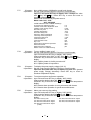
Frequency to repeat ‘20 seconds ON and 3 minutes OFF‘ is depend on the ambient temperature.
AT (AT sensor temperature in F15)
Frequency to repeat ‘20 seconds ON
and 3 minutes OFF’
14
Lower than +5℃
9
+5℃ ~ +14℃
6
+15℃ ~ +24℃
None
Higher than +25℃
AT sensor open or short circuited
9
(6) When the unit completes ‘ON and OFF’ action, High side compressor starts after 3 minutes elapse
since the Low side compressor stops, and the Low side compressor starts again when the cascade
sensor temperature is reached to -34℃.
2. Compressor operation once the chamber temperature is reached to set temperature
(1) The chamber temperature should be controlled by turning both the Low and High side compressor
ON/OFF.
(2) When the chamber temperature is set temperature -1.6℃, both the Low and High side compressor
should be turned OFF.
(3) When the chamber temperature is set temperature -0.4℃ after 3 minutes elapse since the Low
and High side compressor turns OFF, the High side compressor should be solely turned ON.
(4) When the cascade sensor temperature is -34℃ after 1 minute elapse since the High side
compressor turns ON, the Low side compressor should be turned ON.
3. Compressor operation retrieves from momentary power failure or power switch turned off
(1) In the momentary power failure or power switch turned off or set temperature is changed from
-80℃ to -70℃ with battery switch is ON;
<a> When the Low side compressor OFF time is equal or more than 120 minutes, the Low side
compressor should start with warming-up operation.
<b> When the Low side compressor OFF time is less than 120 minutes, the Low side compressor
should start with normal operation in any ambient temperature.
(2) In momentary power failure within 3 seconds, the unit should start operation according with chapter
1. when display temperature is equal or more than set temperature + 10℃.
zThe unit should start operation according with the chapter 1. when the battery switch is OFF.
4. Reactor and breaker
(1) Adjust frequency switch to your adequate frequency to use the reactor which restricts starting
voltage in compressor. Make sure frequency switch should be adjusted correctly with power supply
frequency to start compressor operation correctly.
Frequency switch is located at the rear on the bottom.
(2) Arrange the outlet breaker (refer to Recommended breaker), because compressor should be
energized with 30A for 20 seconds continuously during warming-up operation.
<Recommended breaker>
Motor protection: More than 15A Line protection: More than 30A
1
㩷
Specifications
ŶStructural specifications
Item
Name
External dimensions
Internal dimensions
Effective capacity
Outer door
Inner door
Insulation
Exterior
Interior
Shelf
Outer door latch
Outer door lock
Access port
Refrigeration circuit
Compressor
Evaporator
Condenser
Refrigerant
Refrigerant oil
Power supply
Battery
Weight
Accessories
Optional component
㩷
MDF-U33V / MDF-U32V(N)
Ultra-low Temperature Freezer
W670 × D867 × H1860 (mm)
W490 × D600 × H1140 (mm)
333 L
1 door, painted steel
2 doors, ABS resin panel with stainless frame
Vacuum insulation panel + rigid polyurethane foamed-in place
Painted steel
Painted steel
3 shelves (adjustable), stainless steel
W464 x D535 (mm) Load; 50kg/shelf
1 pc
1 pc
2 places (back, bottom left corner)
inner diameter; ij17mm
Secondary cooling system
High stage side; Hermetic type, Output; 450W
Low stage side; Hermetic type, Output; 750W
Tube on sheet type
High stage side; Fin and tube type
Low stage side; Shell and tube type
High stage side; R-404A
Low stage side; R-508
Ze-NIUS32SA or Ze-NIUSL22SA
Local voltage
Nickel-metal-hydride battery, DC 6V, 1100mAh, Auto recharge
255 Kg
1 set of key, 1 scraper
Automatic temperature recorder (MTR-G85,
MTR-85H+MDF-S3085(Mounting kit))
Back-up system (CVK-UB2); LCO2
Inventory rack (IR-216U, IR-220U)
3 drawers for lower compartment (MDF-30R)
Interface board (MTR-480)
2
ŶControl specifications
Item
Temp. controller
Thermal sensor
Temperature display
Temperature
Door
Alarms
Filter check
Power failure
Remote alarm
Battery check
Fan motor check
Freezer status monitor
Control panel
Key lock function
Self diagnosis
Compressor protection
MDF-U33V / MDF-U32V(N)
Microcomputer control system
Temperature setting range: -50℃∼-90℃ (Unit: 1℃)
Non-volatile memory
Pt.1000ȍ
LED digital display
+5℃~+20℃ for High temperature alarm (Initial; +10℃)
-5℃~-20℃ for Low temperature alarm (Initial; -10℃)
ALARM lamp blinks and buzzer sounds intermittently with 15min. delay
Remote alarm contact; Normal Open, Normal Close
Allowable contact capacity; Max. 30VDC, 2A
DOOR lamp is lit with 2min. delay (Initial; 2min.)
Buzzer delay time is changeable within 2 ~ 15min.
FILTER lamp blinks and buzzer sounds intermittently
ALARM lamp blinks, buzzer sounds intermittently and remote alarm is
output.
Remote alarm terminal 3P; DC30V、2A
NC-COM, NO-COM
BATTERY lamp is lit when battery accumulation time is approx. 3 years
Battery lamp blinks when fan motor accumulation time is approx. 6 years
Status 1: Abnormal ambient temperature (When the ambient temperature
is over than 35℃ or lower than 0℃)
Status 2: Abnormal low voltage (When the power supply voltage is 15%
less than the rated voltage)
Status 3: Overloaded run(When the running rate of compressor (L) is
over than 95%)
Lamps: ALARM, BATTERY, STATUS, DOOR, FILTER
Buzzer key: BUZZER
Alarm test key: ALARM TEST
Status key: STATUS
Set key: SET
Digit shift key:
Numerical value shift key:
Press key for 5 seconds to display;
L0: Key lock OFF L1: Key lock ON
When any failure is occurred in sensor among temp. sensor, filter sensor,
cascade sensor and AT sensor;
zError code and chamber temperature are displayed alternately
zALARM lamp blinks
zRemote alarm activates
zBuzzer sounds intermittently
When the cascade sensor temperature is lower than -34℃, Low side
compressor is turned on.
When the cascade sensor temperature is higher than -18℃, Low side
compressor is turned off.
When the filter sensor is higher than +60℃, High side compressor is
turned off.
Overload relay for Low side compressor, Internal thermometer for High
side compressor
3
㩷
ŶPerformance specifications
Cooling performance
-86℃ at the center of the chamber (AT30℃, no load)
-50℃∼-86℃(AT30℃, no load)
Temperature control range
Power source
Rated power consumption
Noise level
115V, 60Hz
220V, 50Hz
220V, 60Hz
230V, 50Hz
240V, 50Hz
775 W
640 W
710 W
610 W
650 W
49 dB {A} (background noise 20dB)
Maximum pressure
Usable conditions
1.9 MPa
AT; +5℃~+30℃
Humidity: Less than 80%RH
* Design or specifications will be subject to change without notice.
4
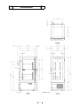
Dimensions
Ceiling
Power cord
Side
5
Front
Cooling unit parts
<MDF-U33V/U32V(N)>
Specifications
Item
H side
L side
Type:C-1RN45L1A
Code:802 021 11
Type:C-1RN45L5A
Code:812 022 15
Type:C-1RN45L5A
Code:812 022 15
Ze-NIUS22SA or Ze-NIUS32SA
Charged q’ty: 230cc
Forced air cooling(partially)
DSH
Type:CS200J1NS-1A
Code:7FB-0-M101-002-02
Type:KS200J1NS-4A
Code:7FB-0-M101-002-04
Type:KS200J1NS-4A1
Code:7FB-0-M101-002-05
Ze-NIUS22SA or Ze-NIUS32SA
Charged q’ty: 850cc
Forced air cooling(partially)
Oil cooler
Fin and tube
12 columns x 3 lines P6.35mm
Fin 38pcs.
W 250mm
φ4.76mm
Cascade condenser
Shell and tube φ80mm
Cascade condenser
Compressor
115V,60Hz
220V,50/60Hz
230/240V,50Hz
Refrigerant oil
Cooling system
Condenser
Type
Condenser
Pre-condenser
Frame pipe
Evaporator
Type
Capillary tube
Resistance
Length
Outer diameter
Inner diameter
Refrigerant
Oil additive
Dryer
Condensing fan
Condensing fan
motor
Type
Oil separator
0.363Mpa
3000mm
φ2.0mm
φ0.9mm
R-404A
Charged q’ty: 509g
Coil pipe
φ6.35mm
ʊ
ʊ
Tube on sheet
φ7.94mm
Ex.tank capillary
0.363Mpa
34 PSI
3000mm
500mm
φ2.0mm
φ2.4mm
(φ0.9mm)
φ1.2mm
R-508
Charged q’ty: 195g
n-Pentane
n-Pentane
Charged-q’ty: 21g
Charged q’ty: 28g
Dry core Type: D-SM032T
4A-XH-6
Charged q’ty: 58g
φ230 mm、4 blades
Material: ABS
115V SE4-E11L1P Output::10W
220∼240V SE4-E11L5P Output:10W
SPK-0S02S2
ʊ
(810-4-2008)
6
7
H side
L side
Service valve
Capillary tube L
Evaporator
Check valve
Refrigeration Circuits
Dryer L
Dryer H
Condenser
Pre-condenser
Capillary tube (EX)
EX tank
L side compressor
Framepipe
Pre-condenser
H side compressor
Oil separator Service valve
Suction heat exchanger
Capillary tube H
Cascade condenser
Accumulator
Pre-condenser
Secondary refrigeration circuits
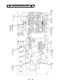
Components on PCB
CNB
To Battery
To Transformer
CN1
To Switching
power supply
CN11
To Temp. sensor
CN2
To Network interface
MTR-480(option)
CN7
To Door switch
To AT sensor
To Filter sensor
To cascade sensor
CN9
To H comp. relay
CN4
To Temp Control relay
To Heater relay
CN6
To Dicplay PCB
CN3
To Remote alarm
terminal
CN5
To Switch PCB
To Buzzer
8
Electrical Parts
MDF-U33V/U32V(N)
Compressor (H)
Starting relay (H)
Starting capacitor (H)
Running capacitor (H)
Condensing fan motor
Compressor (L)
Starting relay (L)
Overload relay (L)
Starting capacitor (L)
Running capacitor (L)
Cap.tube heater
Temp. control relay
H. comp. relay
Heater relay
Temperature sensor
Cascade sensor
Filter sensor
AT sensor
Power transformer
Battery
Battery switch
Power switch
Breaker switch
Switching power supply
Door switch
Noise filter
Type
Code
Rated voltage (50/60Hz)
Winding resistance C-S(Aux)
C-R(Main)
Type
Pick up voltage
Drop out voltage
Rating
Rating
Type
Rating
Thermal fuse
Type
Code
Rated voltage (50/60Hz)
Winding resistance C-S(Aux)
C-R(Main)
Type
Pick up voltage
Drop out voltage
Type
Action to the temp. (No current)
OFF
ON
Action to the current (AT25℃)
Operation time
Non-Action to the temp. (80㷄䋩
Non-Action
Action
Rating
Rating
Rating
Resistance (AT25℃)
Type
Contact capacity
Coil
Type
Contact capacity
Coil
Type
Contact capacity
Coil
Type
Rating
Type
Rating
Type
Rating
Type
Rating
Type
Primary
Secondary
Type
Rating
Type
Rating
Type
Rating
Type
Rating
Type
Input
Output
Type
Rating
Type
Rating
AC115V,60Hz
AC220V,50Hz
AC230/240V,50Hz
AC220V,60Hz
C-1RN45L1A
802 0 2111
115V, 60Hz
2.739ȍ
1.330ȍ
AMVL-165
C-1RN45L5A
812 0 2215
220-240V, 50Hz
14.76ȍ
5.95ȍ
AMVL-300A
C-1RN45L5A
812 0 2215
220-240V, 50Hz
14.76ȍ
5.95ȍ
AMVL-300A
C-1RN45L5A
812 0 2215
220-240V, 50Hz
14.76ȍ
5.95ȍ
AMVL-300A
100㱘F, 160V
40㱘F, 260V
SE4-E11L1P
115VAC, 10W
40㱘F, 300V
12㱘F, 300V
SE4-E11L5P
220-240VAC
40㱘F, 300V
12㱘F, 370V
SE4-E11L5P
220-240VAC
40㱘F, 300V
12㱘F, 370V
SE4-E11L5P
220-240VAC
CS200J1NS-1A
7FB-0-M101-002-02
115V, 60Hz
3.18ȍ
0.64ȍ
AMVL-155BF
KS200J1NS-4A
7FB-0-M101-002-04
220/230V, 50Hz
4.6ȍ
2.1ȍ
AMVL-300TA
KS200J1NS-4A1
7FB-0-M101-002-05
230/240V, 50Hz
4.7ȍ
2.7ȍ
AMVL-300TA
KS200J1NS-7A
7FB-0-M101-002-06
220/230V, 60Hz
4.3ȍ
1.7ȍ
AMVL-300TA
MRA999579200
MRA99954-9201
MRA99960-9201
MRA99954-9201
165+/-5㷄
69+/-11㷄
40.0A
6~16sec
135+/-5㷄
69+/-11㷄
29.5A
6~16sec
120+/-5㷄
61+/-11㷄
20.5A
6~16sec
135+/-5㷄
69+/-11㷄
29.5A
6~16sec
160㱘F, 250V
40㱘F, 260V
115VAC 12W
1102㱅
G4F-11123T
20A, 250VAC
DC12V
G4F-11123T
20A, 250VAC
DC12V
G2R-1A-T
10A, 250V
DC12V
1000㱅
THC-663
502AT-1
5K㱅, 25㷄
502AT-1
5K㱅, 25㷄
502AT-1
5K㱅, 25㷄
S41-RN97PV
115V
9V
5HR-AAC
6V, 1100MAH
SLE6A2-5
4A, 250VAC
A8A-202-1
16A, 250V
160㱘F, 250V
15㱘F, 400V
230VAC 12W
4.7K㱅
G4F-11123T
20A, 250VAC
DC12V
G4F-11123T
20A, 250VAC
DC12V
G2R-1A-T
10A, 250V
DC12V
1000㱅
THC-663
502AT-1
5K㱅, 25㷄
502AT-1
5K㱅, 25㷄
502AT-1
5K㱅, 25㷄
S41-RN97PV
230V
9V
5HR-AAC
6V, 1100MAH
SLE6A2-5
4A, 250VAC
160㱘F, 250V
15㱘F, 400V
230VAC 12W
4.7K㱅
G4F-11123T
20A, 250VAC
DC12V
G4F-11123T
20A, 250VAC
DC12V
G2R-1A-T
10A, 250V
DC12V
1000㱅
THC-663
502AT-1
5K㱅, 25㷄
502AT-1
5K㱅, 25㷄
502AT-1
5K㱅, 25㷄
S41-RN97PV
230V
9V
5HR-AAC
6V, 1100MAH
SLE6A2-5
4A, 250VAC
160㱘F, 250V
15㱘F, 400V
230VAC 12W
4.7K㱅
G4F-11123T
20A, 250VAC
DC12V
G4F-11123T
20A, 250VAC
DC12V
G2R-1A-T
10A, 250V
DC12V
1000㱅
THC-663
502AT-1
5K㱅, 25㷄
502AT-1
5K㱅, 25㷄
502AT-1
5K㱅, 25㷄
S41-RN97PV
230V
9V
5HR-AAC
6V, 1100MAH
SLE6A2-5
4A, 250VAC
BAM215131
15A, 250V
ZWS10-12/J
100-240VAC
DC12V, 0.85A
SPKNA20700
5V, 5MA
ZAC2220-11
AC250V, 20A
BAM215131
15A, 250V
ZWS10-12/J
100-240VAC
DC12V, 0.85A
SPKNA20700
5V, 5MA
ZAC2220-11
AC250V, 20A
BAM215131
15A, 250V
ZWS10-12/J
100-240VAC
DC12V, 0.85A
SPKNA20700
5V, 5MA
ZAC2220-11
AC250V, 20A
ZWS10-12/J
100-240VAC
DC12V, 0.85A
SPKNA20700
5V, 5MA
ZAC2220-11
AC250V, 20A
9
9
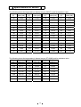
Specifications of sensor
The following shows the temperature in thermal sensor (502AT-1) and its resistance value.
Temp.
Resistance
Temp.
Resistance
Temp.
Resistance
Temp.
Resistance
(℃)
Value (kΩ)
(℃)
Value (kΩ)
(℃)
Value (kΩ)
(℃)
Value (kΩ)
−50
154.5
−36
71.80
−22
35.65
0
13.29
−49
145.9
−35
68.15
−21
33.99
5
10.80
−48
137.8
−34
64.71
−20
32.43
10
8.84
−47
130.2
−33
61.48
−19
30.92
15
7.20
−46
123.1
−32
58.43
−18
29.50
20
6.01
−45
116.5
−31
55.55
−17
28.14
25
5.00
−44
110.2
−30
52.84
−16
26.87
30
4.17
−43
104.4
−29
50.23
−15
25.65
35
3.50
−42
98.87
−28
47.77
−14
24.51
40
2.96
−41
93.70
−27
45.45
−13
23.42
45
2.51
−40
88.85
−26
43.26
−12
22.39
50
2.13
−39
84.18
−25
41.19
−11
21.41
55
1.82
−38
79.80
−24
39.24
−10
20.48
60
1.56
−37
75.67
−23
37.39
−5
16.43
65
1.35
The following shows the temperature in thermal sensor (PT1000ȍ) and its resistance value.
Temp.
Resistance
Temp.
Resistance
Temp.
Resistance
(℃)
Value (Ω)
(℃)
Value (Ω)
(℃)
Value (Ω)
−140
450.83
−70
729.99
0
1000.0
−130
491.47
−60
769.02
10
1038.0
−120
531.83
−50
807.87
20
1076.0
−110
571.92
−40
846.58
30
1113.8
−100
611.76
−30
885.13
40
1151.4
−90
651.38
−20
923.55
50
1189.0
−80
690.78
−10
961.84
60
1226.4
10
Connections on PCB
The following shows the connections of connectors on the Temp. controller PCB.
Connector
Connects to
Usage
CN1
Switching power supply
To supply the power to PCB. (12VDC)
CN2
Network interface
To connect to MTR-480(option)
Remote alarm terminal
CN3
Remote alarm contact outputs.
#1: COM.
In normal condition, open for #1-#2 and
#2: N.O.
closed for #1-#3.
#3: N.C.
CN4
CN5
CN6
To control internal temperature (12VDC)
#1-#2:Temp. control relay
To supply the power to Cap. tube heater
#3-#4:Heater relay
(12VDC)
#1-#5: Switch PCB
To connect to each switch
#6-#7: Buzzer
Display PCB
To connect to each LED
#1-#2: Door switch
To control the door switch
#5-#6: AT sensor
To detect the ambient temperature
#7-#8: Filter sensor
To detect the temperature in condenser outlet pipe.
#9-#10: Cascade sensor
To detect the temperature in cascade.
#1-#2: Battery(#1:6V #2:GND)
To supply the power during power failure
#3-#4: Transformer
To supply the power to PCB. (9VAC)
CN9
#1-#2: H. Comp. relay
To control compressor H ON/OFF (12VDC)
CN10
Unused
CN11
#1-#3: Temp. sensor
CN7
CN8
To detect the internal temperature.
11
Wiring Diagram
<115V,60Hz>
12
12
Wiring Diagram
<220䌾240V,50/60Hz>
13
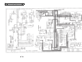
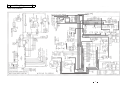
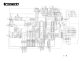
㪚㫀㫉㪺㫌㫀㫋㩷㪛㫀㪸㪾㫉㪸㫄㩷
14
㩷
1.
Control specification
Key and Switch
BUZZER
:
In alarm condition, buzzer stops sounding with this key pressed.
Remote alarm output and alarm message would not be off.
During the power failure (battery back-up), press the key to show the
chamber temperature for 5 seconds.
ALARM TEST
:
With this key pressed to activate alarm test mode to be forcibly step into
alarm condition (ALARM lamp blinks, intermittent buzzer beeps, digital LED
goes off and remote alarm activates).
After approx. 90seconds then, unit retrieves normal condition by Auto
Return.
With the battery switch turns off, “E09” blinks on the display.
SET
:
Press this key once to activate set mode (2nd digit in LED blinks), press the
key again to store the value to be changed.
With Key Lock setting mode (“L 0” or “L 1” is displayed), press the key to
store the value to be changed.
STATUS
:
During STATUS lamp is lit, press this key to display status code among ‘- 1’, ‘- - 2’ and ‘- - 3’.
During setting mode, the blinking digit shifts among the 1st digit or the 2nd
digit or 3rd digit.
In chamber temperature display, press this key over 5 seconds to shift to
Key Lock screen with ‘L_0’ displayed.
During setting mode, count the blinking digit up. In chamber temperature
display, press the key over 5 seconds to enter the function mode. (“F00” is
displayed)
2.
Temperature control
Setting range
: -50㷄~-90㷄
Display range
: -180㷄~+50㷄
Setting procedure : Press SET key and set the required value with
key and
key.
Press SET key to store the set value.
Unacceptable setting If you try to set the value which deviates from setting range, the buzzer
range :
beeps for 1 second to inform the value unacceptable.
3.
Key Lock mode and Function mode
Setting range
: 0, 1
Setting procedure: In chamber temperature display, keep pressing
key over 5 seconds
to enter into Key Lock mode. (“L_0” or “L_1” is displayed. initial: L_0) with
“0” or “1” blinks.
Change the value with
key and press SET key to store the value in
the non-volatile memory.
0: Key Lock inoperative
1: Key Lock operative
15
4.
Function mode
Setting range
Display range
: 00~32
: 00~39
00, 16 and 33~39 are unavailable.
Setting procedure :
In chamber temperature display, keep pressing
key over 5 seconds
to enter function mode (F00 is displayed). Change the blinking 1st digit to
desired function code with
key and
key. Press SET key to be
function code available.
If you input 00 and 16 then press SET key, automatically revert to
chamber temperature display.
Unacceptable setting If you try to input the value among F33~F39, the buzzer beeps to inform
range :
the value unacceptable.
5.
Error codes
E01:
E02:
E03:
E04:
E05:
E06:
E07:
E08:
E09:
E10:
Temp. sensor is open circuited
Temp. sensor is short circuited
Cascade sensor is open circuited
Cascade sensor is short circuited
Filter sensor is open circuited
Filter sensor is short circuited
AT sensor is open circuited
At sensor is short circuited
Battery switch is off position
Compressor temperature is abnormal
(1) Temp. sensor
Open circuit (E01): When temperature in PT sensor is equal or higher than 50㷄, E01 and
50㷄 are displayed alternately and the buzzer beeps intermittently and
remote alarm contact activates.
Compressor keeps forcibly running.
Press BUZZER key to stop the buzzer beeping.
Short circuit (E02): When temperature in PT sensor is equal or lower than -170㷄, E02 and
-170 㷄 ~ -180 㷄 are displayed alternately and the buzzer beeps
intermittently and remote alarm contact activates.
Compressor keeps forcibly running.
Press BUZZER key to stop the buzzer beeping.
(2) Cascade sensor
Open circuit (E03): When temperature in cascade sensor is equal or higher than 60㷄, E03
and chamber temperature are displayed alternately, the buzzer beeps
intermittently and remote alarm contact activates.
High side compressor is forcibly turned on and low side compressor is
turned off.
Press BUZZER key to stop the buzzer beeping.
Short circuit (E04): When temperature in cascade sensor is equal or lower than -65㷄, E04
and chamber temperature are displayed alternately, the buzzer beeps
intermittently and remote alarm contact activates.
High side compressor is forcibly turned on and low side compressor is
not controlled in any cascade temperature.
Press BUZZER key to stop the buzzer beeping.
16
(3) Filter sensor
Open circuit (E05): When the temperature in filter sensor is equal or higher than 130㷄, E05
and chamber temperature are displayed alternately, the buzzer beeps
intermittently and remote alarm contact activates.
High side compressor is forcibly turned off.
Press BUZZER key to stop the buzzer beeping.
Short circuit (E06): When the temperature in filter sensor is equal or lower than -60㷄, E06
and chamber temperature are displayed alternately, the buzzer beeps
intermittently and remote alarm contact activates.
Press BUZZER key to stop the buzzer beeping.
(4) AT sensor
Open circuit (E07): When the temperature in AT sensor is equal or higher than 60㷄, E07
and chamber temperature are displayed alternately, the buzzer beeps
intermittently and remote alarm contact activates.
Unit should have warming-up operation when low side compressor is
turned on.
Press BUZZER key to stop the buzzer beeping.
Short circuit(E08): When the temperature in AT sensor is equal or lower than -60㷄, E08
and chamber temperature are displayed alternately, the buzzer beeps
intermittently and remote alarm contact activates.
Unit should have warming-up operation when low side compressor is
turned on.
Press BUZZER key to stop the buzzer beeping.
(5) Battery SW is off If you press ALARM TEST key when battery switch is off position or
position (E09):
battery is unconnected, E09 is displayed.
(6)Compressor
abnormal
temperature (E10):
When the temperature in filter sensor is equal or higher than 60㷄, E10
and chamber temperature are displayed alternately and high side
compressor is forcibly turned off to inform compressor temperature is
abnormal or fan motor locked.
Press BUZZER key to stop the buzzer beeping.
When the temperature in filter sensor – AT is equal or lower than 10㷄,
compressor is turned on.
(7) Error code priority
No.1:
No.2:
No.3:
No.4:
No.5:
6.
Alarms
High temp. alarm
:
Cascade sensor (E03, E04) … High side compressor is forcibly turned on
Filter sensor (E05, E06) … Compressor protection is uncontrollable
Abnormal compressor temp.(E10) … Compressor temporary turns off
Temp. sensor (E01, E02) … Compressor keeps forcibly running
AT sensor (E07, E08) … Warming-up operation in any AT
When chamber temperature is equal or higher than set temperature +
high temp. alarm set temperature +1.0, ALARM lamp and LED display
blinks, intermittent buzzer beeps with approx. 10 minutes of delay and
remote alarm activates.
When chamber temperature is equal or lower than set temperature,
ALARM lamp and LED display go off, buzzer stops beeping and remote
alarm turns off.
If you press BUZZER key, the buzzer stops beeping instead remote
alarm does not turn off.
17
Low temp. alarm
:
Door alarm
:
Power failure alarm :
7䋮
When chamber temperature is equal or lower than set temperature - low
temp. alarm set temperature -1.0, ALARM lamp and LED display blinks,
intermittent buzzer beeps with approx. 10 minutes of delay and remote
alarm activates.
When chamber temperature is equal or higher than set temperature –
low temp. alarm set temperature, ALARM lamp and LED display go off,
buzzer stops beeping and remote alarm output turns off.
If you press BUZZER key, the buzzer stops beeping instead remote
alarm does not turn off.
Leave the outer door open and DP54 (red lamp) is lit. Buzzer beeps
intermittently after 1~15 min. (Door alarm setting time) has elapsed.
Initial setting time is 2 min. Buzzer does not activate simultaneously with
remote alarm. Once you press BUZZER key, buzzer does not beep again
With the battery switch is on position and power switch is turned off or
the power is interrupted for 3 seconds, ALARM lamp blinks and
intermittent buzzer beeps and remote alarm activates.
When the power retrieves within 3 seconds after the power failed, micro
computer is initialized and remote alarm turns off.
Press BUZZER key to stop buzzer beeping instead remote alarm does
not turn off.
Remote alarm activates until chamber temperature is stabilized.
You can check chamber temperature for 5 seconds if you press BUZZER
key during power failure.
Running rate
Calculation
Running rate = (ON time / (ON time + OFF time)) X 100%
Measuring condition
After 2hrs has elapsed since chamber temperature was equal or less
than set temperature
ON time (min) = The period which P3.1 in IC5 first switches from
Low to HIGH
OFF time (min) = The period which P3.1 in IC5 switches from HIGH
to LOW
Measuring period
Measuring should be started from 2hrs has passed since chamber
temperature is equal or less than set temperature and completed after
8hrs has passed then.
Condition
(a) When ON time and OFF time is higher than 0, you can calculate
running rate. (range 0~100%)
(b) When ON time and OFF time is 0, you cannot calculate running rate.
(c) When ON time is higher than 0 while OFF time is 0, you cannot
calculate running rate.
(d) When ON time is 0 while OFF time is higher than 0, you cannot
calculate running rate.
Reset of calculation
When chamber temperature is higher than set temperature +4C, you
should reset calculation and restart it after chamber temperature would
be stabilized.
18
Diagnosed running rate
=(-(Set temp.)X0.9)+((ATX0.9-4.5㷄))-((Set temp.+85㷄) / 10))
8.
DP52 (orange lamp) is lit in the following status;
Status 1; When AT is equal or higher than 35.0C or AT is equal or
lower than 0C, press STATUS key to display ‘- - 1’.
Status 2; When the value in F23 is equal or less than 85% running
rate, press STATUS key to display ‘- - 2’,
Status 3; When running rate is over than 95%, press STATUS key to
display ‘ - - 3’.
Monitor of status
Diagnosis
(Ex.) Set temperature; -80㷄㩷 AT; 30㷄
Diagnosed running rate; 95% (Fixed)
Running rate; 75% (8Hrs running and 6Hrs compressor ON time)
Running rate (75%) - Diagnosed running rate (95%) < 0
… ‘Normal’ (DP52 is gone off)
Running rate – Diagnosed running rate ≧0
… Overloaded run (DP52 is lit)
Impossible to calculate running rate = 222
… Impossible to diagnose (DP52 is gone off)
Diagnosis should be done in every 8 hours.
㪚㪿㪸㫄㪹㪼㫉㩷
㪚㫆㫄㫇㫉㪼㫊㫊㫆㫉㩷㫋㫌㫉㫅㫊㩷㪦㪥㩷㩿㪈㫊㫋㩷㫋㫀㫄㪼㪀㩷
㪪㫋㪸㫉㫋㩷㫋㫆㩷㪺㫐㪺㫃㪼㩷㫉㫌㫅㩷㪸㫅㪻㩷㪻㫀㪸㪾㫅㫆㫊㫀㫊㩷
㫋㪼㫄㫇㪅
㪪㫋㪸㫉㫋㩷 㫋㫆㩷 㪺㪸㫃㪺㫌㫃㪸㫋㪼
㫉㫌㫅㫅㫀㫅㪾㩷㫉㪸㫋㫀㫆㩷
㪪㫋㪸㫉㫋㩷㫋㫆㩷㪻㫀㪸㪾㫅㫆㫊㪼㩷㫉㫌㫅㫅㫀㫅㪾㩷㫉㪸㫋㪼㩷
䌓㪼㫋㩷㫋㪼㫄㫇㪅
㪚㫆㫄㫇㫉㪼㫊㫊㫆㫉㩷㫋㫌㫉㫅㫊㩷㪦㪝㪝㩷
㩷 㩿㪈㫊㫋㩷㫋㫀㫄㪼㪀㩷
㪩㪼㪸㪺㪿㩷㫋㫆㩷㪪㪭㩷
9.
Other functions
Auto Return
㪏㩷㪟㫉㫊㩷
㪪㫋㪸㪹㫀㫃㫀㫑㪼㪻㩷㫎㫀㫋㪿㩷㪺㫐㪺㫃㪼㩷㫉㫌㫅
㪉㩷㪟㫉㫊㩷
:
Alarm resume time :
Sensor temperature :
㪛㫀㪸㪾㫅㫆㫊㫀㫊㩷㫊㪿㫆㫌㫃㪻㩷㪹㪼㩷㪻㫆㫅㪼㩷㫎㫀㫋㪿㩷㪼㫍㪼㫉㫐㩷
㪏㪿㫆㫌㫉㫊㩷㫌㫅㫋㫀㫃㩷㪺㪿㪸㫄㪹㪼㫉㩷㫋㪼㫄㫇㩷㫀㫊㩷㪿㫀㪾㪿㪼㫉
㫋㪿㪸㫅㩷㪪㪼㫋㩷㫋㪼㫄㫇㪅㪂㪋㪅㪇㩷
If there is not any key operation for 90 seconds in each setting mode,
Key Lock mode and Function mode, automatically reverts to chamber
temperature mode.
Note) Auto Return is not worked in F09 and F10.
This is the function to prevent someone pressing BUZZER key to stop
buzzer beeping when the unit is into alarming condition.
Press BUZZER key to stop buzzer beeping. Buzzer beeps again after a
certain alarm resume time elapses.
Alarm resume time is settable in F25. (See Function mode for details)
F12: Temperature of temp. sensor is displayed
(Ex. -80.2㷄㩷 㸢㩷 displayed as ‘80.2’)
F13: Temperature of cascade sensor is displayed.
(Ex. -34㷄㩷 㸢㩷 displayed as ‘-34㷄’)
F14: Temperature of filter sensor is displayed.
(Ex. 67㷄㩷 㸢㩷 displayed as ‘067’)
F15: Temperature of AT sensor is displayed.
(Ex. 30㷄㩷 㸢㩷 displayed as ‘030’)
19
Battery accumulation F03: Battery accumulation time is displayed.
time
:
(Ex. 2years and 6months accumulated 㸢㩷 displayed as ‘02.5’)
The display shows ’02.8’ to inform the battery exhaustion.
Replace with new battery.
<Reset of accumulation time>
Step into F06. Input ‘409’ and press SET key to turn the display
to ’00.0’ with BATTERY lamp (DP55) goes off.
Condensing fan
F32: Condensing fan motor accumulation time is displayed.
motor accumulation
(Ex. 5years and 6months consumed 㸢 displayed as ’05.5’)
time
: <Reset of accumulation time>
Step into F06. Input ‘419’ and press SET key to turn the display
to ’00.0’ with DP55 lamp goes off.
Note) Notice of condensing fan motor accumulation time is prior to
notice of battery accumulation time.
Capillary
heater F18: Input ‘000’ to stop compressor operation and to conduct
operation
:
electricity in capillary heater. Input ‘000’ again to stop capillary
heater operation when capillary heater is conducted electricity.
Input ‘001’ to have capillary heater inoperative, while the
compressor stops operation in every 18 hours.
ROM version
: F30: ROM version is displayed (Ex. Ver. 1.00 㸢㩷 displayed as “1.00”)
10.
Function mode
F00
Automatically revert to chamber temperature display
F01
Setting of High temp. alarm set temperature
F02
Setting of Low temp. alarm set temperature
F03
Display of battery accumulation time
F04
Setting of Door alarm delay time
F05
Setting of High side compressor delay time
F06
Service code input (code: 384)
F07 *
Temperature Zero Adjustment
F08 *
Cascade sensor Zero Adjustment
F09
Factory test mode …… Unavailable
F10
Factory test mode …… Unavailable
F11
Factory test mode …… Unavailable
F12 *
Display of temperature in temp. sensor
F13 *
Display of temperature in cascade sensor
F14 *
Display of temperature in compressor sensor
F15 *
Display of temperature in AT sensor
F16*
Automatically revert to chamber temperature display
F17 *
Model code setting (Initialization of non-volatile ROM and memory)
F18 *
Capillary heater is forcibly turned on/off
F19
Factory test mode …… Unavailable
F20
Factory test mode ... ... Unavailable
F21
Communication ID set
F22
Communication mode set
F23 *
Display of power supply voltage
F24
Remote alarm terminal output
F25
Alarm resume time set
F26 *
Display of actual operation rate
F27 *
Display of diagnosis value for running rate
F28 *
Display of delay time of permission for measuring running rate (2 hrs timer)
F29 *
Display of delay time of permission for measuring running rate (8 hrs timer)
F30 *
ROM version is displayed
F31 *
Filter alarm
F32 *
Display of condensing fan motor accumulating time
F33~F39 Unused
20
Setting
procedure:
In chamber temperature display, keep pressing
key over 5seconds to display
“F00”.
Input the desired function code with
key and
key.
Press SET key to be function mode available.
* … You should input service code in F06 beforehand.
To cancel service code, input “000” in F06 or turn the power off.
F00:
<Purpose> Simply passing through if entered by mistake.
<Operation> Press SET key in “F00” displayed to revert to chamber temperature
display.
F01:
<Purpose> To set high temp. alarm set temperature
<Operation> Input F01 and press SET key to display “010” (initial value).
Set the value in the range “005”~“020” with
key and
key.
Press SET key to store the value and revert to chamber temperature
display.
F02:
<Purpose> To set low temp. alarm set temperature
<Operation> Input F02 and press SET key to display “-10” (initial value).
Set the value in the range “-05”~“-20” with
key and
key.
Press SET key to store the value and revert to chamber temperature
display.
F03:
<Purpose> Battery accumulation time is displayed
<Operation> Input F03 and press SET key to display alternately F03 with “00.0”
(in case battery used for a month or less). Press SET key to revert
to chamber temperature display.
<Reset> Input ‘409’ and press SET key to initialize battery accumulation time.
(’00.0’ is displayed)
F04:
<Purpose> Door alarm delay time is set
<Operation> Press SET key in “F04” displayed to display ‘002’ (initial setting).
Change your desired value among ‘001’~’015’ with
key and
key and press SET key to store the value and revert to chamber
temperature display.
F05:
<Purpose> To have High side compressor operation being delayed when the
power is supplied or the power retrieves from the power failure.
(Unit: Minute)
<Operation> Input “F05” and press SET key to display “002” (initial).
Change the value in the range “002”~”015” with
key and
key.
Press SET key to store the value and revert to chamber temperature
display.
F06:
<Purpose> Dividing F-code for customer used from service
<Operation> Input F06 and press SET key to display “000” (initial value).
Set to “384” with
key and
key. Press SET key to store the
value and revert to chamber temperature display.
<Reset of battery accumulation time>
Input service code, ‘384’ then ‘409’ to reset battery accumulation
time. Unit automatically reverts to chamber temperature display.
<Reset of fan motor accumulation time>
Input service code, ‘384’ then ‘419’ to reset fan motor accmulation
time. Unit automatically reverts to chamber temperature display.
21
<Cancel> Input F06 and press SET key to display “384”.
Change to “000” with
key and
key. Press SET key to store
the value and revert to chamber temperature display.
Service code ‘384’ is not effective after the reset of battery or fan
motor accumulation time.
Power the unit on and off to initialize (‘000’) service code which is
not memorized in non-volatile memory.
Note) ‘384’ is storied in non-volatile memory during battery back-up.
(battery SW is ON)
F07:
<Purpose> To match temperature of temp. sensor with temperature of center at
the chamber.
<Operation> Input service code in F06 prior to use this mode.
Input F07 and press SET key to display “00.0” (initial value).
Change to the desired value in the range “-4.9”~”04.9” with
key
and
key.
Press SET key to store the value and revert to chamber temperature
display.
F08:
<Purpose> To calibrate temperature of cascade sensor
<Operation> Input service code in F06 prior to use this mode.
Input F08 and press SET key to display “00.0” (initial value).
Change to the desire value in the range “-9.9”~”09.9” with
key
and
key.
Press SET key to store the value and revert to chamber temperature
display.
F12:
<Purpose> To display the temperature of temp. sensor
<Operation> Input service code in F06 prior to use this mode.
Input F12 and press SET key to display alternately F12 and “XX.X”
(present internal temperature). Press SET key to revert to chamber
temperature display. 3 digits indication. Minus “-“ is not indicated.
Ex) “-79.5㷄” 㸢㩷 indicated as “79.5”
F13:
<Purpose> To display the temperature of cascade sensor
<Operation> Input service code in F06 prior to use this mode.
Input F13 and press SET key to display alternately F13 and “XX.X”
(present temperature of cascade sensor). Press SET key to revert to
chamber temperature display.
F14:
<Purpose> To display the temperature of filter sensor
<Operation> Input service code in F06 prior to use this mode.
Input F14 and press SET key to display alternately F14 and “XX.X”
(present temperature of filter sensor). Press SET key to revert to
chamber temperature display.
F15:
<Purpose> To display the temperature of AT sensor
<Operation> Input service code in F06 prior to use this mode.
Input F15 and press SET key to display alternately F15 and “XX.X”
(present temperature of AT sensor). Press SET key to revert to
chamber temperature display.
F16:
<Purpose> Simply passing through if entered by mistake.
<Operation> Press SET key in “F16” displayed to revert to chamber temperature
display.
22
F17:
<Purpose> Non-volatile memory initialization, model code change
<Operation> Service code should be input in F06 prior to use this mode.
Input F17 and press SET key to display “001”. Change the value
with
key and
key. Press SET key to store and revert to
chamber temperature display.
Model code is identified by its power source.
Model code ‘002’: 115V
‘003’: 220-240V
<Initial values in Non-volatile memory>
PT sensor Zero Adjustment value
Cascade sensor Zero Adjustment value
Capillary heater turning on time
Auto Recovery time
Chamber temperature
Door alarm delay time
High temp. alarm temperature
Low temp. alarm temperature
Compressor delay time
Communication ID
Communication mode
Key Lock
Remote alarm and buzzer operation
Filter alarm buzzer
Diagnosed value of Status 3
Data to check non-volatile memory
:0C
:0C
: 8 min.
: 30 min.
: -80 C
: 2 min.
: +10 C
: - 10 C
: 3 min.
: 000
: 000
: OFF
: OFF
: OFF
: ON
:
F18:
<Purpose> To turn capillary heater on/off
<Operation> Service code should be input in F06 prior to use this mode.
Input F18 and Press SET key to display “000” (initial).
Change to desire value “000” or “001” with
key and
key.
Press SET key to store the value and revert to chamber temperature
display.
000: Capillary heater is forcibly turned on/off
001: Capillary heater is inoperative
F23:
<Purpose> To display the power supply voltage (Unit: %)
<Operation> Service code should be input in F06 prior to use this mode.
Input F23 and press SET key to display F23 and ‘xxx’ (present
power supply voltage) alternately. Press SET key to revert to
chamber temperature display.
F24:
<Purpose> To set remote alarm and buzzer operation
<Operation> Input F24 and Press SET key to display “000” (initial).
Change to the desired value with
key and
key.
Press SET key to store the value and revert to chamber temperature
display.
000: Remote alarm operation is not synchronous with buzzer
001: Remote alarm operation is synchronous with buzzer
F25:
<Purpose> Alarm auto recovery time setting
<Operation> Input F25 and press SET key to display “030” (initial).
Change to the desired value with
key and
key.
Press SET key to store the value and revert to chamber temperature
display.
000: Auto recovery OFF
010: Recovers after 10min. elapse
020: Recovers after 20min. elapse
030: Recovers after 30min. elapse
(initial)
23
040: Recovers after 40min. elapse
050: Recovers after 50min. elapse
060: Recovers after 60min. elapse
11.
F26:
<Purpose> Running rate is displayed (unit: %)
<Operation> Service code should be input in F06 prior to use this mode.
Input F26 and press SET key to display alternately F26 with “XXX”
(present running rate).
Press SET key to revert to chamber temperature display.
F27:
<Purpose> Diagnosed value of overloaded running rate is displayed
<Operation> Service code should be input in F06 prior to use this mode.
Input F27 and press SET key to display alternately F27 with “095”
(initial value, present diagnosed value of overloaded running rate).
However ‘000’ is displayed if it does not accumulate 480 min by 8H
timer.
Press SET key to revert to chamber temperature display.
F28:
<Purpose> To display delay time of permission of measuring running rate
(2hrs timer; 000~120 min)
<Operation> Service code should be input in F06 prior to use this mode.
Input F28 and press SET key to display F28 and ‘xxx’ (present count
value) alternately. Press SET key to revert to chamber temperature.
F29:
<Purpose> To display delay time of permission of measuring running rate
(8hrs timer; 000~480 min)
<Operation> Service code should be input in F06 prior to use this mode.
Input F29 and press SET key to display F29 and ‘xxx’ (present count
value) alternately. Press SET key to revert to chamber temperature.
F30:
<Purpose> ROM version is displayed
<Operation> Service code should be input in F06 prior to use this mode.
Input F30 and press SET key to display alternately F30 with “1.00”
(Version 1.00).
Press SET key to revert to chamber temperature display.
F31:
<Purpose> Buzzer setting during filter alarm
<Operation> Input F31 and press SET key to display “001” (initial).
Change to the desired value with
key and
key.
Press SET key to revert to chamber temperature display.
000: Buzzer off
001: Buzzer on
F32:
<Purpose> To display condensing fan motor accumulation time
<Operation> Input F32 and press SET key to display F32 and ’00.0’ (e.g.
Accumulation period should be within 36days) alternately. Press
SET key to revert to chamber temperature display.
<Reset> Input ‘419’ in F06 and press SET key to initialize fan motor
accumulation time. (’00.0’ is displayed)
Low side compressor warming-up operation (for 115V/60Hz model only)
Condition:
When the unit starts running with ambient air is lower than 25㷄, occasionally it
causes the Low side compressor being inoperative. The Low side compressor would
have warming-up operation by added the voltage with specified frequency to start it
without fail.
Timing of the voltage added:
20 seconds with 3 minutes intervals
(*Note) Frequency to add the voltage is depend on the ambient temperature.
24
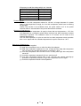
<Frequency to add the voltage with 3 min. interval>
Ambient temp. display
Frequency
14
Equal or lower than 5㷄
9
5~14㷄
6
15 ~ 24㷄
None
Equal or higher than 25㷄
Sensor open or short circuit
9
Re-warming up:
When the Low side compressor seizes for 120 min. or longer because of a power
failure or set temperature change, the Low side compressor would have re-warming
up operation.
(*Note) This function is not available when the power switch is off or the power
retrieves within 3 seconds before the power failure alarm activates.
Abeyance of warming-up:
When the chamber temperature is equal or lower than set temperature + 10㷄, the
unit diagnoses as a temporary power failure and the Low side compressor ceases
warming-up operation. The resistance value in PT sensor can be used as the
chamber temperature.
The unit shifts operation to cycle run and the Low side compressor starts operation
after 1 min. elapse with the cascade temperature is equal or lower than -34㷄.
Sequence of Warming-up:
(1) The power is supplied
(2) High side compressor turns on after the delay time elapses.
(3) High side compressor operates for 3 min. at least and the High side compressor
turns off when the cascade temperature is reached to -34㷄.
(4) Low side compressor turns on with 10 sec. of delay after High side compressor
turned off.
(5) Low side compressor operates for 20 sec. and turns off.
(6) Low side compressor restarts with 3 min. intervals and repeats warming-up
operations as specified frequency. High side compressor turns on again.
(7) Low side compressor follows normal operation.
25
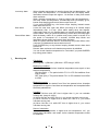
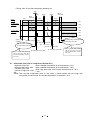
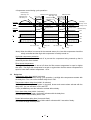
<Timing chart of Low side compressor warming-up>
10sec
20sec
Power
supply
ti
H side comp.
operation
(DP6 is lit)
3min
More
than3min
20sec
3min
More
than1min
20sec
3min
䌏䌎
䌏䌆䌆
䌏䌎
䌏䌆䌆
L side comp.
operation
(DP2 is lit)
䌏䌎
䌏䌆䌆
㽲The power is 㽳H side comp. turns ON
supplied
㽵L side comp. turns ON
㽴H side comp. turns OFF
㽶L side comp. turns
㽵L side comp. turns ON
㽵L side comp. turns ON
㽶L side comp. turns OFF
㽶L side comp. turns OFF
When it elapses 3min at least
after H side comp. turns ON
and the cascade temp. is lower
than -34㷄
12.
㽷L side comp. normal operation
㽷H side comp. turns ON
When it elapses 3min at least
after H side comp. turns ON
and the cascade temp. is lower
than -34㷄
Differential (The point of compressor ON and OFF )
High side comp. ON:
When chamber temperature is set temperature -0.4㷄
High/Low side comp. OFF: When chamber temperature is set temperature -1.6㷄
Low side comp. ON:
When High side comp. turns on and cascade temp. is -34㷄
Interval of High/Low comp. 1 min.
ON:
*Note) The Low side compressor turns on only when 1 minute elapse since the High side
compressor turned on and the cascade temperature is reached to -34㷄.
26
<Compressor control during cycle operation>
Chamber temp.
=Set temp. -0.4
Chamber temp
.=䌓et temp.-1.4
More than1min Chamber temp.
More than1min
=Set temp. -0.䋴
More than 3min
More than 3min
䋨Comp. delay䋩
䋨Comp. delay䋩
Chamber temp
.=䌓et temp.-1.4
Set temp.
Chamber
Temp.
Set temp -0.4㷄
Cascade
temp.=-34㷄
Cascade
temp.=-34㷄
Cascade
temp.
䌓et temp.-1.4㷄
Cascade temp
.=-34㷄
ON
䌈
OFF
ON
䌌
OFF
H/L Comp. OFF
H
ON
L Comp. ON
Comp.
H/L Comp. OFF
H
ON
L Comp. ON
Comp.
*Note) When the failure is occurred in the cascade sensor, the Low side compressor should be
solely controlled and the High side compressor is forcibly turned on.
High side compressor protection:
The High side compressor is turned off to prevent the compressor being warmed up that is
caused by the fan motor locked.
Filter sensor temperature:
The High side compressor is turned off when the filter sensor temperature is equal or higher
than 60㷄. The High side compressor is turned on again when the filter sensor temperature is
equal or lower than ambient temperature +10㷄.
13.
Delay time
Compressor delay time (Initial: 3 minutes)
When the compressor seizes during cycle operation, Low/High side compressors restarts with
the delay time. You can set the desired delay time in F05.
Temperature alarm delay time (Initial: 10 minutes)
When high or low temperature alarm is triggered, buzzer and remote alarm activate with the
delay time. You can set them in F01 and F02.
* Note) ALARM lamp and the indication activate without delay.
Door alarm delay time (Initial: 2 minutes)
When the outer door is open, the buzzer activates with the delay time.
You can set the desired delay time in F04.
Power failure alarm delay time (3 seconds fixed)
When the power is failed, the power failure alarm activates with 3 seconds of delay.
You cannot change the delay time.
27
14.
Prevention for oil logged in the capillary
Purpose:
Capillary heater is conducted electricity by regularly turning both the High and Low side
compressor off to prevent oil logged in the capillary.
Operation:
Both the High and Low side compressor are turned off, while the capillary heater relay (CN4:
3-4) is turned on. DP3 (red lamp) is lit.
Frequency:
8 minutes in every 18 hours (Minutes are changeable in F19)
Timing of operation:
(1) 9 seconds after both the High and Low side compressor are turned off during cycle
operation.
(2) Both the High and Low side compressor are forcibly turned off if they keep running for 60
minutes or more after they were ordered to turn off.
Operation of capillary heater:
Capillary heater is forcibly ON/OFF controlled in F18.
15.
Sensor offset
Sensor offset value:
(1) Temperature sensor: +1.3㷄 (Changeable in F07)
(2) Cascade sensor: +/-0.0㷄 (Changeable in F08)
(3) Filter sensor: +/-0.0㷄
(4) AT sensor: +/-0.0㷄
16.
Remote alarm terminal
Operation:
Once the alarm is triggered, the remote alarm contact (RLY2) switches the position.
Normal
In alarm
17.
CN3
1 – 2 (N.O.) 1 – 3 (N.C.)
Open
Close
Close
Open
Power reset
Setting values after the power is reset:
Alarms: OFF
Compressors: OFF㩷 㩷 㩷 㩷 㩷 㩷 㩷 㩷 㩷 㩷 㩷 㩷
Remote alarm: OFF㩷 㩷 㩷 㩷 㩷 㩷 㩷 㩷 㩷 㩷 㩷 㩷
Alarm resume time: 30 minutes㩷 㩷 㩷 㩷 㩷 㩷 㩷
Door alarm delay time: 2 minutes㩷 㩷 㩷
Timers: Reset
2H timer, 8H timer: 0 (Reset)
Warming-up operation: ON
Counting for Low side compressor OFF period: Reset
Setting data: Referred to non-volatile memory
Momentary power failure:
Status of the unit should be diagnosed by comparing the chamber temperature with the
set temperature. When the chamber temperature is equal or lower than the set
temperature +10㷄, it diagnoses as ‘Momentary power failure’. The Low side compressor
warming-up operation should be cancelled.
28
Setting values after power retrieves from power failure:
Alarms: OFF
Compressors: OFF㩷 㩷 㩷 㩷 㩷 㩷 㩷 㩷 㩷 㩷 㩷 㩷
Remote alarm: ON㩷 㩷 㩷 㩷 㩷 㩷 㩷 㩷 㩷 㩷 㩷 㩷
Door alarm delay time: 2 minutes 㩷 㩷
Setting data: Refer to non-volatile memory
Timers: Reset
2H timer, 8H timer: 0 (Reset)
Warming-up operation: OFF
Counting of period Low side compressor turns off: Reset
18.
Other specifications
Lamp operation:
<Control PCB>
DP1:
DP2:
DP3:
DP4:
DP6:
Orange lamp
Goes off: High/low temp. alarm (15min. delay), sensor error,
power failure
Lit
: Not in alarm condition
Green lamp
Goes off: Low side compressor turns off. (normal condition)
Lit
: Low side compressor turns on.
Red lamp
Goes off: Capillary heater turns off. (normal condition)
Lit
: Capillary heater turns on.
Yellow lamp (Unused)
Green lamp
Goes off: High side compressor turns off. (normal condition)
Lit
: High side compressor turns on.
<Display PCB>
DP51:
DP52:
DP53:
DP54:
DP55:
DP56:
Red lamp
Goes off: Not in alarm condition (normal condition)
Blinks : High/low temp. alarm (without delay), or sensor failure,
or power failure
Green lamp
Goes off: Inoperative
Lit
: In STATUS
Orange lamp
Goes off: Not in filter alarm (normal condition)
Lit
: In filter alarm
Red lamp
Goes off: Inoperative
Lit
: Door ajar
Orange lamp
Lit
: Battery accumulation time is reached to 3 years
Blinks : Fan motor accumulation time is reached to 6 years
Unused
29
Examples of display:
Chamber temp.
Set temp.
Function㩷 㩷 㩷
Decimal point of chamber temp. -80.0
-79.5㷄
Sensor offset㩷 㩷 㩷
-80.0㷄
-5.0
Operation monitoring㩷 㩷 LCP
F03
㩷㩷㩷㩷
Service code㩷 㩷 㩷 384
Error
Set value㩷 㩷 㩷
004
Accumulation time㩷 㩷 8H timer 135
Key Lock㩷 㩷 㩷
L_0
Buzzer tone:
Alarms (except door alarm)
Key operation
Set value memory
Out of settable range
Door alarm
E01
Intermittent tone
Click tone
Click tone
1 second continuous tone
Intermittent tone with shorter intervals than any other
alarms
30
Parts layout
<Temp.controller P.C.B.>
CN5 To display P.C.B.
CN3 To remote alarm terminal
CN6 To display P.C.B.
CN4
To heater relay
and
temp.control
relay
CN9
To H comp. relay
CN7
To cascade sensor,
filter sensor,
AT sensor and
door switch
CN2
To MTR-480
(option)
CN1
To switching
power supply
CN11 To temp. sensor
CN8
To transformer
and battery
<Switching power supply>
CN2 To Temp. controller P.C.B.
CN1 To 12P terminal
31
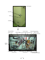
Control panel
Door latch
Handle
PCB BOX
<Electric BOX>
Starting relay L
Comp. H relay
Remote alarm terminal
12P terminal
Battery switch
Temp. control relay Power switch
Power transformer
Starting
relay H
Starting cap. L
Running cap. L
Running cap. H
Heater relay
Starting cap. H
Temp. control PCB
Switching power supply
32
<Lower front>
Filter
AT sensor
<Lower right side>
Filter sensor
Condensing
fan motor
<Lower back side>
33
Compressor L
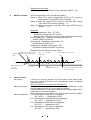
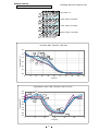
Test data
㶎All the data are the reference only.
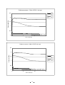
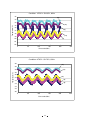
Pull-down and Pull-up data
AT30㷄, No load
㪋㪇
㪉㪇
㪧㫌㫃㫃㪄㫌㫇
㫋㪼㫄㫇㪅䋨㷄䋩
㪇
㪄㪉㪇
㪄㪋㪇
㪄㪍㪇
㪧㫌㫃㫃㪄㪻㫆㫎㫅
㪄㪏㪇
㪄㪈㪇㪇
㪇
㪉
㪋
㪍
㪏
㪈㪇
㪫㫀㫄㪼㩷㫊㪺㪸㫃㪼䋨㪟㫉䋩
34
㪈㪉
㪈㪋
Pulldown pressure 䇭50Hz, AT35㷄, No load
2.5
㪟㪧㪻
㪟㪧㫊
㪣㪧㪻
㪣㪧㫊
Pressure䋨MPa䋩
2
1.5
1
0.5
0
㪇
㪌
㪈㪇
㪈㪌
㪫㫀㫄㪼㩷㫊㪺㪸㫃㪼䋨㪟㫉䋩
㪧㫌㫃㫃㪻㫆㫎㫅㩷㫇㫉㪼㫊㫊㫌㫉㪼䇭㪍㪇㪟㫑㪃㩷㪘㪫㪊㪌㷄㪃㩷㪥㫆㩷㫃㫆㪸㪻
㪉㪅㪌
Pressure䋨MPa䋩
㪉
㪟㪧㪻
㪟㪧㫊
㪣㪧㪻
㪣㪧㫊
㪈㪅㪌
㪈
㪇㪅㪌
㪇
㪇
㪌
㪈㪇
㪫㫀㫄㪼㩷㫊㪺㪸㫃㪼䋨㪟㫉䋩
35
㪈㪌
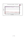
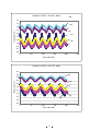
Current and power consumption䇭 115V, 60Hz
Current䋨A䋩/Power consumption䋨kW䋩
㪈㪇
A
kW
㪐
㪏
㪎
㪍
㪌
㪋
㪊
㪉
㪈
㪇
㪇
㪉
㪋
㪍
㪏
㪈㪇
㪈㪉
㪈㪋
㪈㪍
Time scale䋨Hr䋩
220V, 60Hz
A
kW
6
3
5
2.5
4
2
3
1.5
2
1
1
0.5
0
0
0
3
6
9
Time scale(Hr)
36
12
㪧㫆㫎㪼㫉㩷㪺㫆㫅㫊㫌㫄㫇㫋㫀㫆㫅㩷㩿㫂㪮㪀
Current(A)
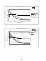
Current and power consumtion
Current and power consumption
230V, 50Hz
A
kW
㪊
4.5
4
㪉㪅㪌
3.5
㪉
Current(A)
3
2.5
㪈㪅㪌
2
㪈
1.5
1
㪇㪅㪌
0.5
㪇
0
㪇
㪊
㪍
Time scale(Hr)
37
㪐
㪈㪉
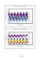
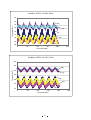
㪟㪆㪣㩷㪜㪭㪘㩷㪦㪬㪫㩷㫋㪼㫄㫇㪼㫉㪸㫋㫌㫉㪼
㪌㪇㪟㫑
㪋㪇
㪚㪿㪸㫄㪹㪼㫉㩷㫋㪼㫄㫇㪅䋨㷄䋩
㪉㪇
㪇
㪟㪜㪭㪘㪦㪬㪫
㪣㪜㪭㪘㪦㪬㪫
㪈㪆㪉㪿
㪘㪫
㪄㪉㪇
㪄㪋㪇
㪄㪍㪇
㪄㪏㪇
㪄㪈㪇㪇
㪇
㪌
㪈㪇
㪈㪌
㪫㫀㫄㪼㩷㫊㪺㪸㫃㪼䋨㪟㫉䋩
㪟㪆㪣㩷㪜㪭㪘㩷㪦㪬㪫㩷㫋㪼㫄㫇㪼㫉㪸㫋㫌㫉㪼
㪍㪇㪟㫑
㪟㪜㪭㪘㪦㪬㪫
㪣㪜㪭㪘㪦㪬㪫
㪈㪆㪉㪿䌡䌩䌲
㪘㪫
㪋㪇
㪚㪿㪸㫄㪹㪼㫉㩷㫋㪼㫄㫇㪅䋨㷄䋩
㪉㪇
㪇
㪄㪉㪇
㪄㪋㪇
㪄㪍㪇
㪄㪏㪇
㪄㪈㪇㪇
㪇
㪌
㪈㪇
㪫㫀㫄㪼㩷㫊㪺㪸㫃㪼䋨㪟㫉䋩
38
㪈㪌
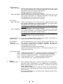
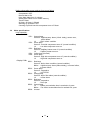
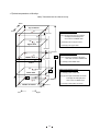
<17points temperature uniformity>
Note) These data are the reference only.
Back
Top of interior
(2)
Front
(4)
(5)
Upper are measuring points
57mm᳂
(1)
(1)~(4): 57mm(H) from the top of interior
27mm(D) and 23mm(W) from
each corners on Middle shelf
(3)
(6)
10mmH
(5): 57mm(H) from the top of interior
Upper shelf
(6): 10mm(H) from Upper shelf
23mmW
(8)
(7)
27mmD
(10)
(11
)
Middle shelf
(9)
Middle area mesuring points
᳂
10mmH
(11): 10mm(H) from Middle shelf
Mullion
(12)
10mmH
Ჾ
Lower shelf
Bottom area measuring points
(12): 10mm(H) from Lower shelf
(16)
᳑
(14)
(7)~(10): 10mm(H), 27mm(D), 23mm(W)
from each corners on Middle shelf
(17)
(13)
Bottom of interior (15)
Left
Right
57mm᳂
39
(13)~(16): 57mm(H) from Bottom of interior
27mm(D) and 23mm(W) from
each corner on Middle shelf
(17): 57mm(H) from Bottom of interior
Condition: SV -80㷄, AT30㷄, 50Hz
Bottom area
-73.9
-74.7
-74.1
-74.6
-73.1
-76.8
-73.9
-76.9
-76.7
-74.4
-76.7
-74.3
-73.0
-73.0
-72.7
-73.0
-73.4
-72.7
㪤㪸㫏
-78.8
-81.1
-78.8
-80.7
-78.4
-78.6
-76.4
-81.2
-80.8
-77.5
-79.3
-75.8
-75.5
-76.3
-75.5
-75.2
-76.7
-81.2
㪤㫀㫅
Upper area
MIN
Middle area
Middle area
Upper area
(1) Left front
(2) Left back
(3) Right front
(4) Right back
(5) Center
(6) Center on uppper shelf
(7) Left front
(8) Left back
(9) Right front
(10) Right back
(11) Center on Middle shelf
(12) Center on lower shelf
(13) Left front
(14) Left back
(15) Right front
(16) Right back
(17) Center
17points measured
MAX
Bottom area
Measured points
Condition: SV -70㷄, AT30㷄, 50Hz
Middle of
Differential
Measured points
cycle
-76.35
±2.45
(1) Left front
-77.90
±3.20
(2) Left back
-76.45
±2.35
(3) Right front
-77.65
±3.05
(4) Right back
-75.75
±2.65
(5) Center
-77.70
±0.90
(6) Center on uppper shelf
-75.15
±1.25
(7) Left front
-79.05
±2.15
(8) Left back
-78.75
±2.05
(9) Right front
-75.95
±1.55
(10) Right back
-78.00
±1.30
(11) Center on Middle shelf
-75.05
±0.75
(12) Center on lower shelf
-74.25
±1.25
(13) Left front
-74.65
±1.65
(14) Left back
-74.10
±1.40
(15) Right front
-74.10
±1.10
(16) Right back
-75.05
±1.65
(17) Center
17points measured
-76.23
㪘㫍㪼
Condition: SV -80㷄, AT20㷄, 50Hz
Bottom area
MIN
-75.7
-76.6
-75.7
-76.3
-75.2
-77.9
-74.5
-77.9
-77.8
-75.3
-77.0
-74.0
-72.7
-73.1
-72.6
-72.6
-72.1
-72.1
㪤㪸㫏
-79.6
-82.0
-80.2
-81.9
-79.3
-79.4
-76.9
-82.0
-81.5
-78.1
-79.7
-75.0
-74.6
-75.7
-74.7
-74.8
-75.7
-82.0
㪤㫀㫅
Upper area
MAX
Middle area
Middle area
Upper area
(1) Left front
(2) Left back
(3) Right front
(4) Right back
(5) Center
(6) Center on uppper shelf
(7) Left front
(8) Left back
(9) Right front
(10) Right back
(11) Center on Middle shelf
(12) Center on lower shelf
(13) Left front
(14) Left back
(15) Right front
(16) Right back
(17) Center
17points measured
MIN
-66.5
-67.9
-66.5
-67.4
-66.0
-68.6
-64.3
-68.4
-68.2
-65.1
-67.4
-62.7
-61.7
-62.8
-61.8
-61.7
-62.4
-61.7
㪤㪸㫏
-71.6
-75.0
-72.3
-74.4
-71.2
-70.9
-66.9
-73.0
-72.4
-68.0
-70.5
-64.1
-63.8
-65.6
-63.6
-64.0
-65.4
-75.0
㪤㫀㫅
Middle of
Differential
cycle
-69.10
±2.55
-71.50
±3.55
-69.40
±2.90
-70.90
±3.50
-68.60
±2.60
-69.80
±1.15
-65.60
±1.30
-70.70
±2.30
-70.30
±2.10
-66.60
±1.45
-69.00
±1.55
-63.40
±0.70
-62.80
±1.05
-64.20
±1.40
-62.70
±0.90
-62.90
±1.15
-63.90
±1.50
-67.14
㪘㫍㪼
Condition: SV -70㷄, AT20㷄, 50Hz
Middle of
Differential
Measured points
cycle
-77.65
±1.95
(1) Left front
-79.30
±2.70
(2) Left back
-77.95
±2.25
(3) Right front
-79.10
±2.80
(4) Right back
-77.25
±2.05
(5) Center
-78.65
±0.75
(6) Center on uppper shelf
-75.70
±1.20
(7) Left front
-79.95
±2.05
(8) Left back
-79.65
±1.85
(9) Right front
-76.70
±1.40
(10) Right back
-78.35
±1.35
(11) Center on Middle shelf
-74.50
±0.50
(12) Center on lower shelf
-73.65
±0.95
(13) Left front
-74.10
±1.30
(14) Left back
-73.65
±1.05
(15) Right front
-73.70
±1.10
(16) Right back
-74.20
±1.50
(17) Center
17points measured
-76.71
㪘㫍㪼
Bottom area
Measured points
MAX
40
MAX
MIN
-66.7
-68.4
-67.1
-68.0
-66.5
-68.7
-64.6
-68.5
-68.2
-65.3
-67.4
-62.7
-61.7
-62.9
-61.6
-61.7
-62.3
-61.6
㪤㪸㫏
-71.9
-75.3
-72.8
-74.8
-71.5
-70.8
-67.0
-73.0
-72.3
-68.2
-70.0
-63.7
-63.3
-65.2
-63.4
-63.6
-64.5
-75.3
㪤㫀㫅
Middle of
Differential
cycle
-69.30
±2.60
-71.85
±3.45
-69.95
±2.85
-71.40
±3.40
-69.00
±2.50
-69.75
±1.05
-65.80
±1.20
-70.75
±2.25
-70.25
±2.05
-66.75
±1.45
-68.70
±1.30
-63.20
±0.50
-62.50
±0.80
-64.05
±1.15
-62.50
±0.90
-62.65
±0.95
-63.40
±1.10
-67.16
㪘㫍㪼
-78.7
-80.4
-79.1
-80.9
-79.8
-79.4
-77.7
-81.9
-78.0
-81.6
-79.1
-75.0
-76.0
-76.2
-75.5
-76.4
-76.1
-81.9
㪤㫀㫅
Measured points
Bottom area
Middle area
Upper area
(1) Left front
(2) Left back
(3) Right front
(4) Right back
(5) Center
(6) Center on uppper shelf
(7) Left front
(8) Left back
(9) Right front
(10) Right back
(11) Center on Middle shelf
(12) Center on lower shelf
(13) Left front
(14) Left back
(15) Right front
(16) Right back
(17) Center
17points measured
MAX
MIN
-66.4
-67.7
-66.9
-67.8
-67.1
-69.5
-65.9
-69.3
-65.8
-69.2
-67.8
-62.3
-64.0
-63.3
-62.6
-62.8
-63.1
-62.3
㪤㪸㫏
-73.0
-75.7
-73.5
-75.9
-74.7
-73.2
-70.0
-75.5
-69.9
-75.3
-71.8
-65.0
-66.0
-66.9
-65.4
-66.5
-66.4
-75.9
㪤㫀㫅
Middle of
Differential
cycle
-69.70
±3.30
-71.70
±4.00
-70.20
±3.30
-71.85
±4.05
-70.90
±3.80
-71.35
±1.85
-69.75
±2.05
-72.40
±3.10
-67.85
±2.05
-72.25
±3.05
-69.80
±2.00
-63.65
±1.35
-65.00
±1.00
-65.10
±1.80
-64.00
±1.40
-64.65
±1.85
-64.75
±1.65
-68.52
㪘㫍㪼
Condition: SV -70㷄, AT20㷄, 60Hz
MAX
MIN
-75.3
-76.6
-75.7
-76.5
-75.8
-78.4
-75.7
-78.5
-75.6
-78.4
-77.3
-73.1
-74.7
-73.6
-73.1
-73.3
-73.9
-73.1
㪤㪸㫏
-79.5
-81.5
-80.0
-81.8
-80.8
-80.1
-78.3
-82.4
-78.2
-82.3
-79.5
-75.1
-76.0
-76.2
-75.4
-76.4
-75.9
-82.4
㪤㫀㫅
Middle of
Differential
cycle
-77.40
±2.10
-79.05
±2.45
-77.85
±2.15
-79.15
±2.65
-78.30
±2.50
-79.25
±0.85
-77.00
±1.30
-80.45
±1.95
-76.90
±1.30
-80.35
±1.95
-78.40
±1.10
-74.10
±1.00
-75.35
±0.65
-74.90
±1.30
-74.25
±1.15
-74.85
±1.55
-74.90
±1.00
-77.20
㪘㫍㪼
Measured points
(1) Left front
(2) Left back
(3) Right front
(4) Right back
(5) Center
(6) Center on uppper shelf
(7) Left front
(8) Left back
(9) Right front
(10) Right back
(11) Center on Middle shelf
(12) Center on lower shelf
(13) Left front
(14) Left back
(15) Right front
(16) Right back
(17) Center
17points measured
Upper area
Condition: SV -80㷄, AT20㷄, 60Hz
(1) Left front
(2) Left back
(3) Right front
(4) Right back
(5) Center
(6) Center on uppper shelf
(7) Left front
(8) Left back
(9) Right front
(10) Right back
(11) Center on Middle shelf
(12) Center on lower shelf
(13) Left front
(14) Left back
(15) Right front
(16) Right back
(17) Center
17points measured
Upper area
-74.3
-75.5
-74.7
-75.6
-75.0
-77.7
-75.3
-78.0
-75.2
-77.9
-76.9
-72.8
-74.6
-73.3
-72.9
-73.2
-73.8
-72.8
㪤㪸㫏
Measured points
Middle area
MIN
Middle area
Bottom area
Middle area
Upper area
(1) Left front
(2) Left back
(3) Right front
(4) Right back
(5) Center
(6) Center on uppper shelf
(7) Left front
(8) Left back
(9) Right front
(10) Right back
(11) Center on Middle shelf
(12) Center on lower shelf
(13) Left front
(14) Left back
(15) Right front
(16) Right back
(17) Center
17points measured
MAX
Bottom area
Measured points
Condition: SV -70㷄, AT30㷄, 60Hz
Middle of
Differential
cycle
-76.50
±2.20
-77.95
±2.45
-76.90
±2.20
-78.25
±2.65
-77.40
±2.40
-78.55
±0.85
-76.50
±1.20
-79.95
±1.95
-76.60
±1.40
-79.75
±1.85
-78.00
±1.10
-73.90
±1.10
-75.30
±0.70
-74.75
±1.45
-74.20
±1.30
-74.80
±1.60
-74.95
±1.15
-76.72
㪘㫍㪼
Bottom area
Condition: SV -80㷄, AT30㷄, 60Hz
41
MAX
MIN
-66.8
-68.1
-67.3
-68.2
-67.6
-69.5
-66.2
-69.2
-65.9
-69.3
-67.9
-62.7
-64.4
-63.7
-62.8
-63.1
-63.5
-62.7
㪤㪸㫏
-73.3
-75.8
-73.8
-76.3
-75.2
-73.2
-69.8
-75.5
-69.7
-75.1
-71.7
-65.2
-66.2
-67.1
-65.4
-66.7
-66.6
-76.3
㪤㫀㫅
Middle of
Differential
cycle
-70.05
±3.25
-71.95
±3.85
-70.55
±3.25
-72.25
±4.05
-71.40
±3.80
-71.35
±1.85
-68.00
±1.80
-72.35
±3.15
-67.80
±1.90
-72.20
±2.90
-69.80
±1.90
-63.95
±1.25
-65.30
±0.90
-65.40
±1.70
-64.10
±1.30
-64.90
±1.80
-65.05
±1.55
-68.61
㪘㫍㪼
Condition: AT30㷄 SV-80㷄, 50Hz
㪄㪎㪉
㪄㪎㪊
Temperature䋨㷄䋩
㪄㪎㪋
(12)
㪄㪎㪌
(17)
㪄㪎㪍
(5)
㪄㪎㪎
(6)
㪄㪎㪏
(11)
㪄㪎㪐
㪄㪏㪇
㪇
㪌㪇
㪈㪇㪇
㪈㪌㪇
㪉㪇㪇
㪉㪌㪇
Time scale䋨Min䋩
Condition: AT30㷄 SV-70㷄, 50Hz
-60
(12)
Temperature䋨㷄䋩
-62
-64
(17)
-66
(5)
-68
(11)
-70
(6)
-72
0
50
100
150
Time scale䋨Min䋩
42
200
250
Condition: AT20㷄 SV-80㷄, 50Hz
-72
-73
(17)
Temperature䋨㷄䋩
-74
-75
(12)
-76
(5)
-77
(11)
-78
-79
(6)
-80
㪇
㪌㪇
㪈㪇㪇
㪈㪌㪇
㪉㪇㪇
㪉㪌㪇
Time scale䋨Min䋩
Condition: AT20㷄, SV-70㷄, 50Hz
-60
Temperature䋨㷄䋩
-62
(12)
-64
(17)
-66
(5)
-68
(11)
-70
(6)
-72
0
50
100
150
Time scale䋨Min䋩
43
200
250
Condition: AT30㷄 SV-80㷄, 60Hz
㪄㪎㪉
(12)
㪄㪎㪊
Temperature䋨㷄䋩
㪄㪎㪋
(17)
㪄㪎㪌
㪄㪎㪍
(5)
㪄㪎㪎
㪄㪎㪏
(11)
㪄㪎㪐
(6)
㪄㪏㪇
㪄㪏㪈
㪄㪏㪉
㪇
㪌㪇
㪈㪇㪇
㪈㪌㪇
㪉㪇㪇
㪉㪌㪇
Time scale䋨Min䋩
Condition: AT30㷄 SV-70㷄, 60Hz
㪄㪍㪇
(12)
㪄㪍㪉
Temperature䋨㷄䋩
㪄㪍㪋
(17)
㪄㪍㪍
㪄㪍㪏
(11)
㪄㪎㪇
(6)
㪄㪎㪉
(5)
㪄㪎㪋
㪄㪎㪍
㪄㪎㪏
㪄㪏㪇
0
50
100
150
Time scale䋨Min䋩
44
200
250
Condition: AT20㷄 SV-80㷄, 60Hz
(12)
㪄㪎㪉
㪄㪎㪊
(17)
Temperature䋨㷄䋩
㪄㪎㪋
㪄㪎㪌
(5)
㪄㪎㪍
(11)
㪄㪎㪎
㪄㪎㪏
(6)
㪄㪎㪐
㪄㪏㪇
㪄㪏㪈
㪄㪏㪉
0
50
100
150
200
250
Time scale䋨Min䋩
Condition: AT20㷄, SV-70㷄, 60Hz
㪄㪍㪇
㪄㪍㪉
(12)
Temperature䋨㷄䋩
㪄㪍㪋
㪄㪍㪍
(17)
㪄㪍㪏
(11)
㪄㪎㪇
㪄㪎㪉
㪄㪎㪋
(6)
㪄㪎㪍
(5)
㪄㪎㪏
㪄㪏㪇
㪇
㪌㪇
㪈㪇㪇
㪈㪌㪇
Time scale䋨Min䋩
45
㪉㪇㪇
㪉㪌㪇
<Power consumption data>
Power source
㩷㩷㩷㩷㩷㩷㩷㩷㩷㩷㩷㩷㩷㩷㩷㩷㩷㩷㩷㪘㪫
㪪㪭
-70㷄
-80㷄
115V60Hz
230V50Hz
(Unit: KWh/day)
220V60Hz
20㷄
30㷄
20㷄
30㷄
20㷄
30㷄
10.7
12.5
8.4
9.8
9.8
11.3
12.0
14.3
9.2
11.0
10.9
13.1
<Maximum heat emission data>
(Unit: kJ)
Power source
115V60Hz 220V50Hz 230V50Hz 240V50Hz 220V60Hz
3420
3024
2664
2808
3204
* These data are the reference only.
46
Sample load test
* Following data is the reference only
Load: Bottle of water (500ml) x 110 䋨 55L in total 䋩
䌡
Top: 500ml x 27
䌢
䌥
Upper: 500ml x 28 bottles
㪺
䌤
Lower: 500ml x 27 bottles
䌦
䌧
Bottom: 500ml x 28 bottles
䌩
䌨
Pull down data䇭(SV-85㷄䋩 with load
30
Temperature䋨㷄䋩
i
d
10
h
f
g
-10
e
b
-30
a
c
-50
-70
-90
0
12
24
36
48
60
72
84
96
108
120
Time䋨Hr䋩
Temperature control䇭data 䋨SV-50㷄㹢-80㷄㹢-50㷄䋩
-40
e
䌢
-45
f
Temperature䋨㷄䋩
-50
g
-55
a
-60
-65
-70
i
h
-75
-80
䌤
䌣
-85
0
12
24
36
Time(Hr)
47
48
60
72