1
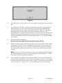
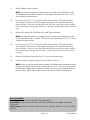
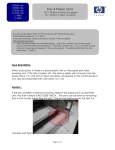
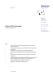
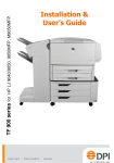
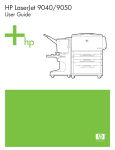
LJ 9000mfp, LJ9040/50mfp, M9040/50mfp, CLJ9500mfp - 30.1.12 and/or 30.1.13 Issue Security Level: HP and Channel Partner Internal use Date: August 11, 2008 rev N Document Summary Communication problem between the SCB, analog boards and CPB MUST follow troubleshooting procedure for SCB Flash and values. Please read entire document prior to and while performing repair. Issue Description: When powering on unit, after the engine has initialized, the engine will establish communication with the copy module. After it has established communication, the copy module will then start to initialize. The SCB will communicate with the ASICS on the analog boards for both the front and backside optical units. If this communication does not occur properly the printer will post a SCAN ERROR, 30.1.12 ADF (backside) or 30.1.13 Scanner (front side). It may also post both errors simultaneously, these control panel messages flash and change very quickly so be very careful when determining the exact error messages being displayed. Print and review the Event Log to verify the particular error condition the MFP is experiencing. After the initial failure and a part has been replaced, there may or may not at this time be a firmware mismatch between the SCB (scanner control board) and the analog boards. If there is a mismatch, it will be necessary to enter service mode to have the SCB Flash Upgrade performed so that the SCB may “talk” to the analog boards. Should this fail, there are Clock/Density values that may need to be input as well. NOTE: It is imperative that you follow the instructions, step by step from #1 to #20, exactly as they are written to resolve the issue. When replacing parts you should only use NEW parts Agents: It is imperative that you follow the instructions exactly as they are written in this document in order to resolve the issue. If this issue is confirmed, consult with an SSOE before dispatching a technician and parts to bring visibility to the number of cases being seen for this specific issue. Dispatch all the parts listed below. Document Summary Difficult issue to document - must read entire document Need to follow troubleshooting procedure for SCB Flash and values. Communication problem between the SCB, analog boards and CPB Page 1 of 7 HP Confidential Parts that should be dispatched with each service call: Part Description Flatbed Optical Assembly ADF Optical Assembly Flatbed Intermediate PCB Scanner Control Board ADF Analog PCB LJ9000mfp RG5-6263-070CN RG5-6307-020CN RH5-3073-030CN RH5-3075-090CN RH5-3082-000CN LJ9040/50mfp RG5-6263-070CN RG5-6307-020CN RH5-3073-030CN RH5-3075-090CN NA CLJ9500mfp RG5-7374-040CN RG5-7380-020CN RH5-3073-030CN RH5-3122-030CN RH5-3082-000CN Note: We recommend sending all the associated parts with the field service engineer so they have a better opportunity to achieve a first time resolution. ONLY install the parts that are found to be defective as you move through the troubleshooting steps. Return unused parts to the parts organization for credit. Troubleshooting Instructions The Control Panel message flashes and changes rapidly so you need to VERIFY your particular error condition by reviewing the Event Log before proceeding. After the initial failure AND a part has been replaced, you may or may not have a firmware mismatch between the SCB (scanner control board) and the analog boards. If there is a mismatch, you will need to enter Service Mode to have the SCB Flash Upgrade performed so that the SCB may “talk” to the analog boards. Should this fail, there are Clock/Density values that may need to be input, as well. The following is a troubleshooting flow with actions for resolution: 1. If both errors (30.1.12 and 30.1.13) are occurring and NO parts have been replaced, please go to Step 2. If either of these errors is showing independently and parts HAVE been replaced, please continue with Step 2. If both errors (30.1.12 and 30.1.13) are occurring and SCB has been replaced with a NEW PART, continue with Step 2. (You should only replace SCB again if no resolve) If Event Log shows only 30.01.12 or 30.01.13 events AND NO PARTS HAVE BEEN REPLACED YET, follow the service manual for troubleshooting, parts recommended and replacement procedures. 2. Power the printer off; verify all calibration white strips are present, clean and in good condition. If platen has been removed reinstall, wait about 30 seconds and power the MFP on again. If the error persists, continue with next step. DO NOT perform power on test with Platen glass removed. Perform Scanner Lamp tests. Check both Lower and Upper lamps to eliminate HW related issues. From the Diagnostics menu, Scanner Tests, check the Lower Lamp and the Upper Lamp. If either Lamp is not functioning follow the instructions in the service manual for repair. If lamps are functional continue to next step. 3. NOTE: When testing upper lamp do not lift the ADF > 30 and you MUST defeat the ADF open/closed sensor under the front left corner of the ADF 4. Enter Service Mode via the front control panel of the MFP. 00900001 for LJ9000MFP 11904004 for LJ9040MFP 11905004 for LJ9050MFP Page 2 of 7 HP Confidential 04904008 For M9040MFP 04905008 For M9050MFP 11950004 for CLJ9500MF 5. Check and Validate CLOCK/DENSITY settings against the values on the label under the control panel or if not available with defaults listed in this document. Enter or change values as needed and select SET for each value even if it already correct. Values of 000 or 255 have been seen these must be corrected for the unit to operate correctly. 6. Save the scanner Settings to the hard drive. Enter Service Mode, Scanner Settings, Save Settings. Without saving the settings they may revert back after power cycle or SCB Flash. 7. Cycle Power – If error is gone you are done, if not continue with next step. 8. Select Scanner Settings, SCB Flash Firmware. NOTE: The following minimum firmware levels are required for the SCB flash Firmware: LJ9000/9000L MFP – 03.779.0 LJ9040/9050MFP - 08.021.7 CLJ9500MFP – 08.021.7 Select OK to start the download when directed to do so as shown in figure 1. Figure 1 9. Once the upgrade finishes, you will be instructed to power the MFP off as shown in figure 2. It is important that you wait until this message posts prior to turning the unit off. Generally this only takes 2 to 10 minutes but it has been seen to take up to 2 hours to complete the flash. When the message appears power the unit off and on again waiting about 30 seconds between turning power off and on. Allow the unit to boot fully, then power the unit off and on again, waiting 30 seconds between turning power off and on. NOTE: You may see the screen change from Performing Upgrade back to the error message; this DOES NOT indicate a failure or completion. DO NOT CYCLE POWER UNTIL YOU SEE THE SCREEN BELOW!!! Page 3 of 7 HP Confidential Figure 2 10. Verify that the 30.1.12 and/or 30.1.13 error has cleared. If error persists, continue with next step. 11. Power off the unit. Verify that all cables and connections on the Scanner control Board and ADF Analog PCB are not loose, improperly seated, broken or damaged. Check that the Scanner Control Board seats properly with the Intermediate PCB. Check FFC’s under platen glass metal covers and reseat. Make sure the brown latches that hold the FFC to the Intermediate PCB are not broken and fully latched. If you have found one of the above to be in question and have performed appropriate service, Power the unit back on and perform the SCB Flash Upgrade in Service Mode as outlined in steps 8 and 9. If error still persists continue with next step. 12. Replace the Scanner Control Board. (IF you have previously replaced the SCB with a NEW part skip to STEP 13) 13. Restore the Scanner Settings to Scanner Control Board. Enter Service Mode, Scanner Settings, Restore Settings. Check to see if the Clock/Density values are valid. If not you will need to reenter them. Again, make sure you select SET for each clock/density value. Power the MFP off, wait about 30 seconds and power the unit on. If the errors are still present, proceed to next step. NOTE: A 30.01.16 error may now also be present. This may be cleared by performing the ADF Width calibration in Service menu/Scanner settings prior to performing step 11. Follow the onscreen instructions to perform the calibration. 14. Perform the SCB Flash Upgrade in Service Mode as outlined in steps 8 and 9. Power the unit off and on again waiting about 30 seconds between turning power off and on. Allow the unit to boot fully, then power the unit off and on again, waiting 30 seconds between turning power off and on. If the 30.1.12 and/or 30.1.13 errors are still present, continue with next step. Page 4 of 7 HP Confidential 15. Re-enter Clock/Density Values and Scanner Calibration values. The scanner calibration values are located on a label inside the front upper control panel cover. Older LJ9000 MFP units did not have the Clock/Density Values on the label inside the front upper control panel cover. Determine whether or not the Clock/Density settings are on the label on the front upper cover beneath the control panel. If the Clock/Density values are present on the label, they should be re-entered. The photo below shows where the clock and density settings are located on the label beneath the control panel. Clock and Density Settings Page 5 of 7 HP Confidential The table below shows how the values on the label correspond with the values in the Service Menu. Value on Label Φ1 Φ2B CP RS Density Corresponding Service Menu Setting H XP1 Clock Set Up 1 L XP1 Clock Set Up 2 H XP2 Clock Set Up 1 L XP2 Clock Set Up 2 H XCP Clock Set Up 1 L XCP Clock Set Up 2 H XRS Clock Set Up 1 L XRS Clock Set Up 2 Gain Density Set Up 1 Offset Density Set Up 2 If the values are not present on the label, then use the Clock/Density values below. NOTE: Please be aware that after each value for the Clock/Density settings are input, the menu returns to the top of the list. Please verify when selecting which value to input next that it is the correct one. For example XP1 Clock Set UP 1 is at the top of the list. After inputting XCP Clock Set UP 1 the menu will return to XP1 Clock Set Up 1. XP1 Clock Set Up 1 = XP1 Clock Set Up 2 = XP2 Clock Set Up 1 = XP2 Clock Set Up 2 = XCP Clock Set Up 1 = XCP Clock Set Up 2 = XRS Clock Set Up 1 = XRS Clock Set Up 2 = 36 27 24 24 105 19 84 9 Density Set Up 1 = 102 Density Set Up 2 = 10 NOTE: You must first SET the Values in the Clock/Density menu then make sure you go back into Scanner Settings and select SAVE SETTINGS. Without saving the settings they may revert back after power cycle or SCB Flash. 16. Once the values are entered, Power the unit off and on again waiting about 30 seconds between turning power off and on. Allow the unit to boot fully, then power the unit off and on again, waiting 30 seconds between turning power off and on. If the errors are still present, proceed with next step. Page 6 of 7 HP Confidential 17. Replace Flatbed Optical Assembly. NOTE: The adjustment values for the image scanner may need to be re-calibrated once the new Flatbed optical assembly is installed. This should be performed after the 30.01.12/13 error condition has been resolved. 18. Power the unit on (30.1.12/13 errors will still be present). Perform SCB Flash Upgrade in Service Mode; Power the unit off and on again waiting about 30 seconds between turning power off and on. Allow the unit to boot fully, then power the unit off and on again, waiting 30 seconds between turning power off and on. If the errors are still present continue with next step. 19. Replace ADF Analog PCB (LJ9000mfp only) or ADF Optical Assembly. NOTE: The adjustment values for the image scanner may need to be re-calibrated once the new ADF optical assembly is installed. This should be performed after the 30.01.12/13 error condition has been resolved. 20. Power the unit on (30.1.12/13 errors will still be present). Perform SCB Flash Upgrade in Service Mode; Power the unit off and on again waiting about 30 seconds between turning power off and on. Allow the unit to boot fully, then power the unit off and on again, waiting 30 seconds between turning power off and on. If the errors are still present continue with next step. 21. Re-enter Clock/Density Values from Step 12. Power unit off and on again. 22. If the errors persist, contact the support center for further instructions. NOTE: If either or both the analog optical assembly or the flatbed optical assembly have been replaced in the MFP during the course of resolving the 30.01.12/13 errors, you must perform the ADF and/or Flatbed scanner calibration procedure to ensure proper image placement on the copied jobs. Follow the procedure in the service manual to perform the calibrations. Document Attributes Author: Jeff D’Andrea Current Product MFP Technical Marketing Product Models: LJ 9000 MFP, LJ9000l MFP, LJ9040MFP, LJ9050MFP, M9040MFP, M9050MFP CLJ9500MFP Product Numbers: C8523A, Q2458A, Q2622A, Q2623A, Q3726A, Q3728A, CC394A, CC395A, C8549A Page 7 of 7 HP Confidential