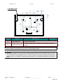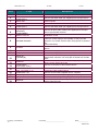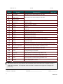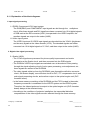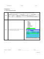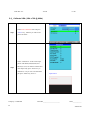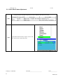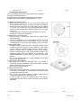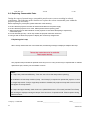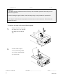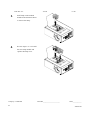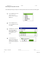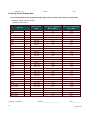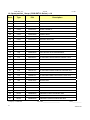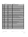
1
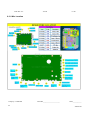
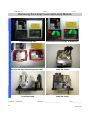
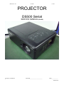
Delta Elec. Inc. Vivitek rev.00 PROJECTOR D5500 Serial SERVICE MANUAL (Rev.00) Company Confidential 1 VIVITEK_______________________ Delta____________ 2008/07/28 Delta Elec. Inc. Vivitek rev.00 DLP DIGITAL PROJECTOR Rev.00 Model Name: D5500 Serial Revision 00 Preliminary Company Confidential 2 Description VIVITEK_______________________ Date 07/28/2008 Delta____________ 2008/07/28 Delta Elec. Inc. Vivitek rev.00 CONTENTS 1. COMPLIANCE OF SAFE REPAIR .........................................................………………………………..…….……5 1-1. Caution during disassembling and assembling ..................……………………………………..…….……5 1-2. Lamp .......... ..............................................................……………………………………………….……….….5 1-3. Lens ............................................................…………………………………………………….…………….….5 2. SPECIFICATIONS .........................................................…………………………………………………………..…6 2-1. Optical Specifications ……………………………………………………………………………………..………6 2-2. Electrical Specifications ……………………………………………………………………………..……………7 2-3. Mechanical Specifications …………………………………………………………………………………...….8 2-4.Environmental considerations…………………………………………………………….………….……...….8 2-5. Views of projector parts……………………………………………………………………………………………9 2-6. Top features…………………………………………………………………………………………………….…..11 2-7. Terminal panel features.………………………………………………………………………………….………14 2-8. Remote control parts…………………………………………………………………………………………..…16 2-9. Inserting the remote control batteries……………………………………………………………………..….18 2-10. Block Diagram ……………………………………………………………..……………………………..…..…19 2-11. Explanation of the block diagrams …………………………………………...………..……………………20 2-12. Wire Location ……………………………………………………………..….……………………………...…..22 3. TROUBLE SHOOTING ……………………………………………………………………………….……………..…23 3-1. Operation check ………………………………………………………..…………………………………………23 3-2. Main Board check ……………………………………………………………………………………………..….24 3-3. LED State Indications ………………………………………………………….………………………………...26 4. DISASSEMBLY AND ASSEMBLY ………………………………………….…………………………………..…….27 5. ADJUSTMENT………………………………………………………………………………………………………..….57 5-1. Step of Into Service mode………………………………………….…………………………..………………..57 5-2. Calibrate VGA (1024 x 768 @ 60Hz)………….....................................................................……………....58 5-3. Calibrate YUV…………………………………………………………………………………….…………..…….59 5-4. Calibrate Video……………………………………………………………………………………………………..60 5-5. Color Wheel Index Adjustment……………………………………………………………….………….……..63 5-6. Focus Adjustment…………………………………………………………………………………………………65 6. SECURITY NOTICE………………………………………………………………………………………………..…...72 6-1. Preventing the Unauthorized Use of the Projector……………………………..………………………..….72 6-2. Unlocking the Projector…………………………………………………………………………………..……...74 6-3. Security function notice………………………………………………………………………………………….74 7. Circuit Protections ………………………………………………………………………………………………….....75 Company Confidential 3 VIVITEK_______________________ Delta____________ 2008/07/28 Delta Elec. Inc. Vivitek rev.00 7-1. Fuse ………………………………………………………………………………………………………………..75 7-2 Thermostat ………………………………………………………………………………………………………...76 7-3 Bimetal ……………………………………………………………………………………………………………..77 7-4 Lamp Interlock Switch …………………………………………………………………………………………..78 8. Maintenance …………………………………………………………………………………………………………...79 8-1 Cleaning the projector …………………………………………………………………………………………..79 8-2 Replacing Consumable Parts ………………………………………………………………………………….83 9. Factory Preset Display Modes ……………………………………………………………………………………..87 10. Spare part list ………….…………….…..……………………………………………………….……………….…91 11. Required adjustments when the parts replaced ………………………………..……….….…………………96 Company Confidential 4 VIVITEK_______________________ Delta____________ 2008/07/28 Delta Elec. Inc. Vivitek rev.00 1. COMPLIANCE OF SAFE REPAIR Be sure to read this Service Manual before providing services. In the projector, full consideration is taken to ensure the safety for a fire, electric shock, injury, harmful radiation, and substance. Therefore, observe the notice described in this Service Manual so that the safety is kept when providing services. Moreover, be sure to observe the notice described in the Instruction Manual. Pay attention to the following during service inspection. 1-1. Cautions during disassembling and assembling 1.This equipment contains parts under high voltage. When making repairs, etc. Be sure to pull out the power plug beforehand to insure safety. 2. Parts may be very hot immediately after use. Make sure the equipment has cooled off sufficiently before carrying out repairs. 3. Make sure that parts and screws and wiring, etc. are returned to their original positions. Tube, tape and other insulation materials have been used for safety reasons. The internal wiring has been designed to avoid direct contact with hot parts or parts under high voltage when using clamps or other tools. 4. The parts used in this device have special safety features such as flame-resistance and anti-voltage properties. When replacing parts, always use parts supplied from the factory. 5. After finishing operations make sure that all parts and wires have been returned to their original position and that there has been no deterioration of the area around the location that was worked on. 6. Be sure to use an earth band (wrist band) during repair and inspection. 1-2. Lamp During current conduction, the lamp is in the high-temperature state. In this case, pay careful attention because a high voltage is used. When replacing a lamp, replace it after confirming that the lamp has gotten cold sufficiently. 1-3. Lens Do not look through a lens during projection. This damages your eyes. Company Confidential 5 VIVITEK_______________________ Delta____________ 2008/07/28 Delta Elec. Inc. Vivitek rev.00 2. SPECIFICATIONS This section provides technical information about the projector's performance. 2-1. Optical Specifications Item Description Projection system Single DLP® chip, 5 segment color wheel Resolution 1024 x 768 pixels* (up to UXGA @ 60 Hz, up to SXGA+ @ 60 Hz on DVI-D) Lamp 260 W AC (230 W in Eco mode), Dual lamp system Image size (diagonal) 50" - 200" / 1.27m - 5.08m (GC805G) 40" - 500" / 1.02m – 12.7m (GB942G, GB940G, GB949G, GB957G) Lens options GC805G: Power focus, throw ratio 0.77:1, F2.0, f=11.4 mm GB942G: Power zoom and focus, throw ratio 1.33-1.79:1, F1.8-2.3, f=19.3-25.8 mm GB940G: Power zoom and focus, throw ratio 1.78-2.35:1, F1.7-1.9, f=26-34 mm GB949G: Power zoom and focus, throw ratio 2.22-4.43:1, F2.1-2.9, f=32-63 mm GB957G: Power zoom and focus, throw ratio 4.43-8.3:1, F2.2-3.1, f=63.5-117.4 mm Lens shift Vertical + 0.5V, Horizontal +/- 0.1H (GB942G, GB940G, GB949G, GC805G) *Effective pixels are more than 99.99% Company Confidential 6 VIVITEK_______________________ Delta____________ 2008/07/28 Delta Elec. Inc. Vivitek rev.00 2-2. Electrical Specifications Item Description Inputs 1 Analog RGB (Mini D-Sub 15P), 1 Analog RGB R/Cr, G/Y, B/Cb, H, V (BNC x 5), 1 Digital RGB (DVI-D 24P), 1 Component Y, Cb/Pb, Cr/Pr (RCA x 3), 1 Component (Mini D-Sub 15P) shared with COMPUTER 1 IN, 1 S-Video (Mini DIN 4P), 1 Video, 3 Stereo Mini Audio, 2 (L/R) RCA Audio. Outputs 1 RGB (Mini D-Sub 15P), 1 Stereo Mini Audio, 1 Screen Trigger Control 1 PC Control Port (D-Sub 9P) USB Port 1 B Type (for Service) LAN Port RJ-45 Video Compatibility NTSC, NTSC4.43, PAL, PAL-60/N/M/B/G/H/I), SECAM, HDTV: 1080i, 720p, SDTV: 576p, 576i, 480p, 480i Scan Rate Horizontal: 15 kHz, 31 to 90 kHz (RGB: 31 kHz or over) Vertical: 50 Hz to 85 Hz Video Bandwidth RGB: 100 MHz (-3dB) Color Reproduction 16.7 million colors simultaneously, Full color Horizontal Resolution NTSC / NTSC4.43 / PAL / PAL-M / PAL-N / PAL60: 540 TV lines SECAM: 300 TV lines RGB: 1024 dots (H) x 768 dots (V) External Control RS232, IR, LAN Sync Compatibility Separate Sync / Composite Sync / Sync on G Built-in Speakers 3W x 2 Power Requirement 100 - 240V AC, 50/60Hz Input Current 7.7A Power Consumption 655W in Dual Lamp Normal mode / 580W in Dual Lamp Eco mode 350W in Single Lamp Normal mode / 315W in Single Lamp Eco mode < 30W in Standby mode Normal < 5W in Standby mode Power saving Company Confidential 7 VIVITEK_______________________ Delta____________ 2008/07/28 Delta Elec. Inc. Vivitek rev.00 2-3. Mechanical Specifications Item Description 19.9" (W) x 7.6" (H) x 15.2" (D) 505 mm (W) x 192 mm (H) x 385 mm (D) (not including protrusions) 45.1 lbs/20.5 kg Dimensions Weight 2-4. Environmental Considerations Item Description Operational Temperatures 41° to 104°F / 5° to 40°C, 10% to 90% humidity (non-condensing) Storage Temperatures 14° to 140°F (-10° to 60°C), 5% to 90% humidity (non-condensing) Optional Parts The parts listed below are optionally available. When ordering those parts, specify the item name and Model No. to the sales dealer Standard Zoom Lens : GB940G Long Zoom Lens : GB949G Ultra Long Zoom Lens : GB957G Short Zoom Lens : GB942G Fixed Short Zoom Lens : GC805G Company Confidential 8 VIVITEK_______________________ Delta____________ 2008/07/28 Delta Elec. Inc. Vivitek rev.00 2-5. Views of projector parts 1. Top view ITEM LABEL DESCRIPTION 1. Lens control panel See Lens Controls 2. Right-hand speaker Right-hand speaker 3. Lamp cover Remove cover to replace lamp or color wheel 4. Exhaust vent Exhaust vent – do not obstruct 5. Rear intake vent Rear cooling intake – do not obstruct 6. OSD control panel See OSD Controls and Status LEDs 7. Left intake vent Left-hand cooling intake – do not obstruct 8. Left-hand speaker Left-hand speaker Company Confidential 9 VIVITEK_______________________ SEE PAGE: Delta____________ 2008/07/28 Delta Elec. Inc. Vivitek rev.00 2. Bottom view ITEM LABEL DESCRIPTION SEE PAGE: 1. Height adjusters Adjust projection height 2. Ceiling support holes Contact your dealer for information on mounting the projector on a ceiling Note: When installing, ensure that you use only UL Listed ceiling mounts. Caution: With ceiling installation, use approved mounting hardware & M4 screws; maximum depth of screw: 12 mm; distance from ceiling/ wall: 20 cm (0.7 feet) for proper ventilation; distance from fluorescent lamps: at least 1 m (3 feet) front and back of the projector. For permanent installations, follow local codes. Company Confidential 10 VIVITEK_______________________ Delta____________ 2008/07/28 Delta Elec. Inc. Vivitek rev.00 2-6. Top Features 1. Lens Controls ITEM LABEL 1. ZOOM 2. UP CURSOR 3. RIGHT CURSOR 4. DOWN CURSOR 5. LEFT CURSOR 6. FOCUS Company Confidential 11 DESCRIPTION Increase/decrease projected image size Move image left, right, up, or down Focus the projected image VIVITEK_______________________ Delta____________ 2008/07/28 Delta Elec. Inc. Vivitek rev.00 2. OSD Controls and Status LEDs ITEM LABEL DESCRIPTION SEE PAGE: 1. MENU Open / Close the OSD 2. UP/ DOWN/ LEFT/ RIGHT BUTTONS Navigate and change settings in the OSD 3. RIGHT CURSOR/ VOLUME INCREASE Increase volume 4. CANCEL Exit the On-Screen Display (OSD) 5. SOURCE Detects the input device 6. POWER Turn the projector on or off (main power switch must be turned on first). Press to place the projector in standby mode. 7. LAMP 2 (LED) 8. LAMP 1 (LED) Green Flashing Green Flashing See Indicator Messages See Indicator Messages Green 9. WARNING (LED) Red Orange See Indicator Messages Flashing Company Confidential 12 VIVITEK_______________________ Delta____________ 2008/07/28 Delta Elec. Inc. ITEM Vivitek LABEL DESCRIPTION rev.00 SEE PAGE: Green 10. POWER (LED) Orange See Indicator Messages Flashing 11. AUTO Select or change settings in the OSD 12. 13. Optimize image size, position, and resolution LEFT CURSOR/VOLUME DECREASE Company Confidential 13 Decrease volume VIVITEK_______________________ Delta____________ 2008/07/28 Delta Elec. Inc. Vivitek rev.00 2-7. Terminal Panel Features Company Confidential 14 VIVITEK_______________________ Delta____________ 2008/07/28 Delta Elec. Inc. ITEM 1. 2. 3. 4. Vivitek LABEL COMPUTER 3 IN AUDIO IN COMPUTER 3 AUDIO OUT 7. MONITOR OUT AUDIO IN COMPUTER 2 AUDIO IN [L (MONO)/R] (COMPONENT) SERIAL PORT IN 8. SCREEN TRIGGER 9. S-VIDEO 5. 6. 10. 11. 12. 13. 14. 15. 16. 17. 18. 19. POWER SWITCH AC IN AUDIO IN [L(MONO)/R] VIDEO IN COMPONENT IN (Y,Pb/Cb, Pr/Cr) COMPUTER 2 IN (R/Cr, G/Y, B/Cb, H, V) COMPUTER 1 IN rev.00 DESCRIPTION Connect the DVI-D cable (not supplied) from a computer Connect the audio cable (not supplied) from the input device Audio loop-thru Connect to a monitor Connect the audio cable (not supplied) from the input device Connect an RCA audio cables (not supplied) from the input device right and left channels Installation control When connected to the screen through a comercially available cable, the screen deploys automatically on start up of the projector. The screen retracts when the projector is powered off (see notes below) Connect a commercially available S-video cable from a video device Turn on/off the projector Connect the supplied power cable Connect RCA audio cables (not supplied) from the input device right and left channels. This audio jack is shared with S-Video input. Connect a composite video cable (not supplied) from a video device to the yellow RCA jack Connect a component video enabled device Connect RGBHV or Component signal from com- puter or component video enabled device Connect a VGA cable (supplied) from a computer AUDIO IN(COMPUTER 1) Connect the audio cable (not supplied) from the input device LAN Connect a LAN cable (not supplied) from a computer Connect the USB cable (not supplied) from a computer. For service personnel only. SERVICE Company Confidential 15 VIVITEK_______________________ Delta____________ 2008/07/28 Delta Elec. Inc. Vivitek rev.00 2-8. Remote Control Parts Important: 1. Avoid using the projector with bright fluorescent lighting turned on. Certain high-frequency fluorescent lights can disrupt remote control operation. 2. Be sure nothing obstructs the path between the remote control and the projector. If the path between the remote control and the projector is obstructed, you can bounce the signal off certain reflective surfaces such as projector screens. 3. The buttons and keys on the projector have the same functions as the corresponding buttons on the remote control. This user’s manual describes the functions based on the remote control. ITEM LABEL DESCRIPTION SEE PAGE: 1. Status LED Lights when the remote control is used 2. Laser Use as on screen pointer. DO NOT POINT IN EYES. 3. Up Up arrow when connected through USB to a PC 4. Right Right arrow when connected through USB to a PC 5. Down Down arrow when connected through USB to a PC 6. Page Down Page down when connected through USB to a PC Company Confidential 16 VIVITEK_______________________ Delta____________ 2008/07/28 Delta Elec. Inc. ITEM Vivitek LABEL rev.00 DESCRIPTION 7. Up cursor Navigates and changes settings in the OSD 8. Right cursor Navigates and changes settings in the OSD 9. Down cursor 10. Volume +/- Adjusts volume 11. Mute Mutes the built-in speaker 12. Zoom+ Zoom in 13. Zoom- Zoom out 14. Freeze Freeze/unfreezes the on-screen picture 15. Blank Makes the screen blank 16. Source Detects the input device 17. Auto Auto adjustment for phase, tracking, size, position 18. Menu Opens the OSD 19. Status 20. Keystone top/bottom Corrects image-trapezoid (wider top/bottom) effect 21. Left cursor Navigates and changes settings in the OSD 22. Enter Changes settings in the OSD 23. Page Up Page up when connected through USB to a PC 24. Left Left arrow when connected through USB to a PC 25. Enter Enter key when connected through USB to a PC 26. Power Turns the projector on or off SEE PAGE: Opens the OSD Status menu (the menu only opens when an input Note: The remote control can only interface with a computer when connected to the computer through a USB cable connection. The computer cable connects a computer to the projector for display purposes only. Company Confidential VIVITEK_______________________ Delta____________ 17 2008/07/28 Delta Elec. Inc. Vivitek rev.00 2.9. Inserting the Remote Control Batteries 1. Remove the battery compartment cover by sliding the cover in the direction of the arrow. 2. Insert the supplied batteries taking note of the polarity (+/-) as shown here. 3. Replace the cover. Caution: 1. Only use AAA batteries. (Alkaline is better). 2. Dispose of used batteries according to local ordinance regulations. 3. Remove the battery when not using the projector for prolonged periods. Company Confidential VIVITEK_______________________ Delta____________ 18 2008/07/28 Delta Elec. Inc. Vivitek rev.00 2-10. Block Diagram Company Confidential VIVITEK_______________________ Delta____________ 19 2008/07/28 Delta Elec. Inc. Vivitek rev.00 2-11. Explanation of the block diagrams 1. Input signal processing 1-1.RGB & Component & DVI input system The RGB(5BNC) and COMPONENT input signals are led through the multiplexer circuit. After these signals and DVI signal have been converted into 10-bit digital signals of RGB each at the A/D converter (U201) incorporated in the VIDEO amplifier, the resultant signals are output to the scaler (U400). 1-2.Video input system The VIDEO input and S-VIDEO input signals are decoded into the Y/CbCr (brightness and chroma) signals at the video decoder (U702). The decoded signals are further converted into 10-bit digital signals of Y/ CbCr, and then output to the scaler (U400). 2. Digital video signal processing 2-1.Scaler (U400) • The Y/CbCr signals are processed for picture quality improvement and matrix processing at the Scaler circuit, and then converted into the RGB signals. • The RGB and VIDEO input signals are switched over at the selector. After passing through the signal adjusting circuit of color space processing, auto-adjustment, etc., these signals are written in the RLDRAM. • The video signals called up from the RLDRAM, pass through the definition converter circuit, ON-screen display, error diffusion circuit for DLP, V-T compensator circuit, and such signal processing circuits, and are then output to the optical engine unit (DLP formatter board). • In the frame memory consisting of the RLDRAM and the FIFO located in the scaler, frequency conversion is conducted for the WRITE system and the READ system. Therefore, the video signals can be output to the optical engine unit (DLP formatter board) always at the constant timing. • According to the conditions of projector installation, the trapezoidal distortion compensation of the video signals are also effected through the frame memory. Company Confidential VIVITEK_______________________ Delta____________ 20 2008/07/28 Delta Elec. Inc. Vivitek rev.00 3. Audio signal processing • The audio output is generated from the speakers via the amplifier (U900) provided with a volume control. • The volume control is conducted by the DC output from the D/A converter (U900). 4. System control The scaler (U400) controls all of this system. 5. Power circuit 1. Main power supply • In the state of standby, the power is supplied 5V to the scaler, scaler peripheral ICs, and FLASHROM. • After the power is ON, the power at 2.5V, 3.3V, 5.7Vand 13V is fed to the analog circuit, fan, formatter board, etc. 2. Lamp power supply • The lamp is lit with POWER ON. • Unlighting detection is performed. 6. Safety design • Fan circuit detection • Lamp cover detection • Lamp house temperature detection • Thermal protector for the lamp power supply • Lamp replacing time Company Confidential VIVITEK_______________________ Delta____________ 21 2008/07/28 Delta Elec. Inc. Vivitek rev.00 2-12. Wire Location Company Confidential VIVITEK_______________________ Delta____________ 22 2008/07/28 Delta Elec. Inc. Vivitek rev.00 3. TROUBLE SHOOTING 3-1. Operation check By making operation checks under normally operating conditions, a certain degree of judgment is possible on errors. Prior to the removal of the top cover, check the POWER indicator and the STATUS indicator. Company Confidential VIVITEK_______________________ Delta____________ 23 2008/07/28 Delta Elec. Inc. Vivitek rev.00 3-2. Main Board check Company Confidential VIVITEK_______________________ Delta____________ 24 2008/07/28 Delta Elec. Inc. Vivitek rev.00 CN110 CN109 Company Confidential VIVITEK_______________________ Delta____________ 25 2008/07/28 Delta Elec. Inc. Vivitek rev.00 3-3. LED State Indications Power LED Projector Status LED Condition LED Sequence Projector Condition AC Off OFF OFF OFF Cooling ORANGE BLINK 0.5sON > 0.5sOFF After Power OFF Power up sequence GREEN BLINK 0.5sON > 0.5sOFF Start up Standby / Idle ORANGE ON ON Standby Power ON GREEN ON ON ON Projector Status LED Condition LED Sequence Projector Condition Normal Condition OFF OFF Power ON Cover ERROR RED 1 time BLINK (repeatedly) 0.5sON > 2.5sOFF ERROR Temperature ERROR RED 2 times BLINK (repeatedly) (0.5sON > 0.5sOFF) * 2 > 2.0sOFF ERROR Power ERROR RED 3 times BLINK (0.5sON > 0.5sOFF) * 3 > 2.0sOFF ERROR FAN ERROR RED 4 times BLINK (repeatedly) (0.5sON > 0.5sOFF) * 4 > 2.0sOFF ERROR Keylocked (when push key) ORANGE light up ON Keylock function enable Standby (Power-saving) OFF OFF Standby (Power-saving) Standby (Normal) GREEN LIGNT ON Standby (Normal) Projector Status LED Condition LED Sequence Projector Condition Lamp Off OFF OFF Lamp Off End of the Lamp life RED BLINK 0.5sON > 0.5sOFF Replace Lamp NO LAMP RED 1 time BLINK (repeatedly) 0.5sON > 2.5sOFF ERROR Lamp ERROR RED 6 times BLINK (repeatedly) (0.5sON > 0.5sOFF) * 6 > 2.0sOFF ERROR Cooling Lamp ORANGE BLINK 0.5sON > 0.5sOFF Switching Lamp 1 & 2 Re-Light up sequence GREEN BLINK 0.5sON > 0.5sOFF Start up Lamp life Over RED ON ON Replace Lamp Eco mode ORANGE ON ON Power ON Normal mode GREEN ON ON Power ON WARNING LED Lamp LED Company Confidential VIVITEK_______________________ Delta____________ 26 2008/07/28 Delta Elec. Inc. Vivitek rev.00 4. DISASSEMBLY AND ASSEMBLY Removing the Lamp Cover and Lamp Module D I S Look the full set projector. Look at the IO side. Look at the keypad of top side. Look at the keypad of top side. Loose these four screws. Remove and take out the lamp cover. A S S E M B L Y Company Confidential VIVITEK_______________________ Delta____________ 27 2008/07/28 Delta Elec. Inc. Vivitek rev.00 Removing the Lamp Cover and Lamp Module D I S Look at the top side. Loose these four screws and take out. A S S E M Remove the lamp modules (upward view). Look the Lamp. B L Y Look the Lamp. Company Confidential Look the Lamp. VIVITEK_______________________ Delta____________ 28 2008/07/28 Delta Elec. Inc. Vivitek rev.00 Removing the Lamp Module and Front cover D I Look the Lamp. Look the Lamp. Remove the ten screws. Look the screws. Remove the front cover. Front side views. S A S S E M B L Y Company Confidential VIVITEK_______________________ Delta____________ 29 2008/07/28 Delta Elec. Inc. Vivitek rev.00 Removing the Back & Top cover D I S Back cover view. Remove the ten screws. Remove the back cover. Back side view. A S S E M B L PULL Y Pull the top cove in this direction. Company Confidential Then remove the Top cover. VIVITEK_______________________ Delta____________ 30 2008/07/28 Delta Elec. Inc. Vivitek rev.00 Removing the Top cover & Keypad board D I S Remove the FCC Cable from the keypad side. Look the top cover & keypad BD. Remove the 7 screws. Then remove the keypad BD. Remove the 7 screws. Remove the shield. A S S E M B L Y Company Confidential VIVITEK_______________________ Delta____________ 31 2008/07/28 Delta Elec. Inc. Vivitek rev.00 Removing the Top cover Shield D I S Remove the twelve screws, and careful and check this place when you assembled. Check this hook-buckle when you assemble that. Disconnect. Careful this area and check this place when you assemble this plate. Then remove the top cover shield. Top cover shield & screws. A S S E M B L Y Company Confidential VIVITEK_______________________ Delta____________ 32 2008/07/28 Delta Elec. Inc. Vivitek rev.00 Replace the color wheel D I S Remove the four screws and take away. Review the color wheel. Review the color wheel. Remove the three screws. Remove the three screws and take this case away. Color wheel module off. A S S E M B L Y Company Confidential VIVITEK_______________________ Delta____________ 33 2008/07/28 Delta Elec. Inc. Vivitek rev.00 Replace the color wheel and Removing the Lens D I S Review the color wheel. Review the color wheel. Color wheel module off. Look at the Lens release button. A S S E M B L Y Push the Lens release button, Turn antiClockwise and pulled the lens away. Company Confidential The Optical Lens review. VIVITEK_______________________ Delta____________ 34 2008/07/28 Delta Elec. Inc. Vivitek rev.00 Removing the Lens cap & lens ring D I S Remove the screw. Remove the Lens cap & front IR assy. Disassemble the Lens cap & IR assy. Front IR BD views. Remove this screw. Take off the lens ring. A S S E M B L Y Company Confidential VIVITEK_______________________ Delta____________ 35 2008/07/28 Delta Elec. Inc. Vivitek rev.00 Removing the Main Board D I S Remove the five screws. Then take off the shield. Remove the screw & disconnect the wire. Disassemble the back IR assy. Remove these two screws. Remove the two hexagonal bolts then take off the main BD. A S S E M B L Y Company Confidential VIVITEK_______________________ Delta____________ 36 2008/07/28 Delta Elec. Inc. Vivitek rev.00 Review the Main Board D I S A S S Review the Main Board Top side. E M B L Y Review the Main Board Bottom side. Company Confidential VIVITEK_______________________ Delta____________ 37 2008/07/28 Delta Elec. Inc. Vivitek rev.00 Removing the Lamp cover D I S Unplug these two hook-buckles, then disconnect. Remove these four screws. Review the screws. Arrange the wires as picture when you assemble it. Unplug these four hook-buckles and careful the assembly. Careful and check this place when you assembled. A S S E M B L Y Company Confidential VIVITEK_______________________ Delta____________ 38 2008/07/28 Delta Elec. Inc. Vivitek rev.00 Removing the Lamp cover & Lamp module D I this place when you Careful and check this place when you S Careful and check assembled. assembled. A S S E M Unplug and check this hook-buckle. Review the Lamp cover. The Lamp cover off. View the Fan module area. B L Y Company Confidential VIVITEK_______________________ Delta____________ 39 2008/07/28 Delta Elec. Inc. Vivitek rev.00 Removing the FAN module D I S Take these two sets away. Take these two fans away. Care the fan wire assembly. See the connector location. A S S E M B L Y Be careful the two side of arrow mark direction. Company Confidential Be careful the two side of arrow mark direction. VIVITEK_______________________ Delta____________ 40 2008/07/28 Delta Elec. Inc. Vivitek rev.00 Removing the Fan module & Optical module D I S Take these two sets away. Be careful the hook-buckles. Remove these six screws. Remove the screw. Then Remove the Optical engine module. Review the screws. A S S E M B L Y Company Confidential VIVITEK_______________________ Delta____________ 41 2008/07/28 Delta Elec. Inc. Vivitek rev.00 Removing the Optical module & Lens Shift / motor module D I S Careful and check this place when you assembled. Careful and check this place when you assembled. The Optical module off. Remove these six screws. Review the screws. Remove the Lens Shift / motor module. A S S E M B L Y Company Confidential VIVITEK_______________________ Delta____________ 42 2008/07/28 Delta Elec. Inc. Vivitek rev.00 Remove the Lens Shift / motor module and Power shield D I S The Lens Shift / motor module off. Careful and check this place when you assembled. Careful and check this place when you Careful and check this place when you assembled. assembled. Remove these 8 screws Review the screws. A S S E M B L Y Company Confidential VIVITEK_______________________ Delta____________ 43 2008/07/28 Delta Elec. Inc. Vivitek rev.00 Removing the Power shield & Lamp holder D I S Arrange the wires as picture when you assemble it. Careful and check this place when you assembled. Careful and check this place when you assembled. Review the Power Shield. Remove these five screws. Review the screws. A S S E M B L Y Company Confidential VIVITEK_______________________ Delta____________ 44 2008/07/28 Delta Elec. Inc. Vivitek rev.00 Removing the Lamp holder and Take care the assembly D I S Arrange the wires as picture when you assemble it. Arrange the wires as picture when you assemble it. Disassemble this connector. Disconnect the connectors. Then remove the Lamp holder module. Careful and check this place when you assembled. A S S E M B L Y Company Confidential VIVITEK_______________________ Delta____________ 45 2008/07/28 Delta Elec. Inc. Vivitek rev.00 Removing the blown Fan & Power Fan D I S Remove the two screws. Review the screws. Review the Fan. See the connector location. Arrange the wires as picture when you assemble it. Remove the Power Fan. A S S E M B L Y Company Confidential VIVITEK_______________________ Delta____________ 46 2008/07/28 Delta Elec. Inc. Vivitek rev.00 Removing the power fan & ballast shield D I S View the Fan off. Remove the five screws,then take off the shield. Review the screws. Remove the two screws. Remove the two screws. Review the screws. A S S E M B L Y Company Confidential VIVITEK_______________________ Delta____________ 47 2008/07/28 Delta Elec. Inc. Vivitek rev.00 Removing the power Assy & ballast Assy D I S Disconnect the connectors. Then take off the power Assy. Remove the screw. Remove the screw Careful and check this place when you assembled. Careful and check this place when you assembled. A S S E M B L Y Company Confidential VIVITEK_______________________ Delta____________ 48 2008/07/28 Delta Elec. Inc. Vivitek rev.00 Remove Audio Board and Module D I S Review the Audio module. Careful and check this wire when you assembled. Arrange the wires as picture when you assemble it. Arrange the wires as picture when you assemble it. A S S E M B L Y Arrange the wires as picture when you assemble it. Company Confidential VIVITEK_______________________ Delta____________ 49 2008/07/28 Delta Elec. Inc. Vivitek rev.00 Remove Audio Board and Module D I S Careful and check this place when you assembled. Arrange the wires as picture when you assemble it. Remove the all hook-buckle. Disconnect the connector. Arrange the wires as picture when you assemble it. Remove these two screws. A S S E M B L Y Company Confidential VIVITEK_______________________ Delta____________ 50 2008/07/28 Delta Elec. Inc. Vivitek rev.00 Remove Audio Board / Module and IO Board D I S Remove these two screws. Review the screws. Disconnect the connector. Remove the Audio module. A S S E M B L Y Remove th two screws & hexagonal bolts. Company Confidential VIVITEK_______________________ Delta____________ 51 2008/07/28 Delta Elec. Inc. Vivitek rev.00 Remove IO Board D I S Remove these three screws. Review the screws. Then remove the IO BD Assy. Remove the seven screws. Remove the eight hexagonal bolts. Remove the IO BD. A S S E M B L Y Company Confidential VIVITEK_______________________ Delta____________ 52 2008/07/28 Delta Elec. Inc. Vivitek rev.00 Remove the protection BD & the speaker D I S Remove these 8 screws and the Transformer & Power saving Board take away. Remove the Fan. A S S E M Remove the two screws and take away Remove the three screws and take away the L speaker. the shield. B L Y Remove the two screws and take away the R speaker. Company Confidential VIVITEK_______________________ Delta____________ 53 2008/07/28 Delta Elec. Inc. Vivitek rev.00 Remove BD ADJ FOOT & Bottom shield D I S A Remove the two screws and take away the ADJ foot. Review the ADJ FOOT and screw. S S E M B Remove these 14 screws and take away the Remove these screws and take away the three parts. Bottom shield. L Y Review these parts and screws. Company Confidential VIVITEK_______________________ Delta____________ 54 2008/07/28 Delta Elec. Inc. Vivitek rev.00 Review the Bottom case D I S A S S E M B L Y Company Confidential Review the Bottom case. VIVITEK_______________________ Delta____________ 55 2008/07/28 Delta Elec. Inc. Vivitek rev.00 Appendix. Screw torque for D5500 Page Screw Type 29 M3*L8 32 M3*L8 35 M4*L10 38 M3*L8 41 M3*L10 41 M4*L16 42 M4*L12 46 M3*L8 47 M3*L8 51 M3*L8 52 M3*L8 54 M3*L8 Company Confidential P/N Screw Driver Torque (kg-cm) 3100330800 3.5~4.0 3.5~4.0 5.5~6.0 3.5~4.0 3.5~4.0 5.5~6.0 5.5~6.0 3.5~4.0 3.5~4.0 3.5~4.0 3.5~4.0 3.5~4.0 3100300800 3109020700 3100300800 3100301000 3105120300 3102301200 3100300800 3100300800 3100300800 3100300800 3100300800 VIVITEK_______________________ Delta____________ 56 2008/07/28 Delta Elec. Inc. Vivitek rev.00 5. Adjustment 5-1 .Step of Into Service mode Using the remote controller and press key as below method to enter the service mode. Step1 Open Main menu and select “Expert ” item to enter Step2 the expert menu as right side picture. Company Confidential VIVITEK_______________________ Delta____________ 57 2008/07/28 Delta Elec. Inc. Vivitek rev.00 5-2 . Calibrate VGA (1024 x 768 @ 60Hz) Select ADC Calibration Item and press Step1 “Select” key , and then you will see the picture as follow。 Select “Calibration”. In this menu input pattern with White(240,240,240) and Black(16,16,16) for calibrate VGA Source . Step2 After input ready press “Select” key to calibration, or if you won’t do calibration just press “Menu” key to leave。 Company Confidential Input Pattern VIVITEK_______________________ Delta____________ 58 2008/07/28 Delta Elec. Inc. Vivitek rev.00 5-3. Calibrate YUV In Service Mode Select ADC Calibration Step1 Item and press “Select” key , and then you will see the picture as follow。 Select “Calibration”. In this menu input pattern with 75﹪SMPTE pattern for calibrate YUV Source and notice that the Step2 input source must be 480p format 。 After input ready press “Select” key to proceed, or if you won’t do calibration just press “Menu” key to leave。 Company Confidential Input Pattern VIVITEK_______________________ Delta____________ 59 2008/07/28 Delta Elec. Inc. Vivitek rev.00 5-4. Calibrate Video In Service Mode Select DEC Calibration Step1 Item and press “Select” key , and then you will see the picture as follow。 Select “Calibration”. In this menu input pattern with 75﹪SMPTE pattern for calibrate video source and notice that the Step2 input source must be NTSC format 。 After input ready press “Select” key to Input Pattern proceed, or if you won’t do calibration just press “Menu” key to leave。 Company Confidential VIVITEK_______________________ Delta____________ 60 2008/07/28 Delta Elec. Inc. Vivitek rev.00 YUV Calibration: Test Equipment: VG-828 Input Timing: 480P (Timing 953) Input Pattern: SMPTE Color Bar(Pattern 984) Red Level Blue Level White Level Black Level Company Confidential VIVITEK_______________________ Delta____________ 61 2008/07/28 Delta Elec. Inc. Vivitek rev.00 Video Calibration: Test Equipment: VG-828 Input Timing: NTSC (Timing 946) Input Pattern: SMPTE Color Bar(Pattern 984) White Level Black Level Company Confidential VIVITEK_______________________ Delta____________ 62 2008/07/28 Delta Elec. Inc. Vivitek rev.00 5-5. Color Wheel Index Adjustment Using the remote controller and press key as below method to enter the service mode. Step1 Open Main menu and select “Expert ” item to enter Step2 the expert menu as right side picture. Company Confidential VIVITEK_______________________ Delta____________ 63 2008/07/28 Delta Elec. Inc. Vivitek rev.00 Select “Color Wheel Index” (The default value is 29. The range is 0~360.) In this menu input pattern with “16 Gray Scale”. Fine-tune until the gray scale still distinct. Decrease the color to the minimum. Then switch “256 Gray Scale”, tune off G, B channel, check the smooth in brighter level of the R 256 ramp. If not, fine tune until R 256 ramp smooth. Step3 [Notice] This Color Wheel Index value will be setting to the projector’s control board. If change projector’s control board, the Color Wheel Index value must be re-adjusted by service engineer. Company Confidential VIVITEK_______________________ Delta____________ 64 2008/07/28 Delta Elec. Inc. Vivitek rev.00 5-6. Focus Adjustment 1. Remove the cosmetic lens cover (A) B A 2. Remove the cosmetic lens cover (B) B Company Confidential VIVITEK_______________________ Delta____________ 65 2008/07/28 Delta Elec. Inc. Vivitek rev.00 3. Remove the cosmetic lens cover (B) by screw Screw 4. Without Cosmetic Cover Figure Company Confidential VIVITEK_______________________ Delta____________ 66 2008/07/28 Delta Elec. Inc. Vivitek rev.00 5. The adjustment structure of lens mount Image adjustment screw Fixed Screw Company Confidential VIVITEK_______________________ Delta____________ 67 2008/07/28 Delta Elec. Inc. Vivitek rev.00 6. The function of lens mount adjustment Projector Screw for adjustment Image curvature Screen 7. Adjustment Procedure a. Move projection lens to be at center position of DMD b. Rotate fixed screw counterclockwise around 15 to 30 degree (loosen it) c. Adjust the image adjustment screw to make image on screen from corner position to center position to be clear d. Tighten the fixed screw Company Confidential VIVITEK_______________________ Delta____________ 68 2008/07/28 Delta Elec. Inc. Vivitek rev.00 (A) Move PJ Lens at center position of DMD Input projector with cross pattern, then zoom-in and zoom out projection lens that center cross image overlap by adjusting lens shift. (B) Rotate fixed screw counterclockwise around 15 to 30 degree (loosen it) Fixed Screw Company Confidential VIVITEK_______________________ Delta____________ 69 2008/07/28 Delta Elec. Inc. Vivitek rev.00 (C1)Adjust image adjustment screw to make image on screen from corner position to center position to be clear Image Criteria Pixel Shape is clear Coma flare is less then 2.5 pixel (C2)Adjustment Hint If upper area image on screen is ahead of screen then rotate image adjustment screw clockwise of upper screw 4 Company Confidential VIVITEK_______________________ Delta____________ 70 2008/07/28 Delta Elec. Inc. Vivitek rev.00 (D) Tighten fixed screw then glue it Company Confidential VIVITEK_______________________ Delta____________ 71 2008/07/28 Delta Elec. Inc. Vivitek rev.00 6. Security Notice 6-1. Preventing the Unauthorized Use of the Projector The projector has an inbuilt security feature to lock the OSD control panels and deny remote control operation. The security feature has no default keyword; in the first instance of enabling the security feature, the user must define a keyword. Locking the Projector To setup the security keyword, refer to the following guide. 1. Press Menu on the OSD control panel on the projector or remote control to display the Main Menu. Scroll to the Setting menu using ▲or▼ and press Select. 2. The Setting menu is displayed. Select the Installation tab using ◄or► and select PIN code lock using ▲or▼. Press Select. Company Confidential VIVITEK_______________________ Delta____________ 72 2008/07/28 Delta Elec. Inc. 3. Vivitek rev.00 You are prompted to enable the PIN code lock Function. Select OK and press Select. Select On using the ▼ button. 4. The PIN code lock window is displayed. Enter a keyword between 4 and 10 characters using ▲▼◄►. Press Select. 5. Once a successful keyword is entered, a confirmation screen is displayed. Enter the same password as the previous step and write it down for later reference. Press Select. A security activation message is displayed. Select Cancel to return to the Setting menu or select OK to enable PIN code lock. Company Confidential VIVITEK_______________________ Delta____________ 73 2008/07/28 Delta Elec. Inc. Vivitek rev.00 6-2. Unlocking the Projector To unlock the projector, refer to the following guide. 1. When the projector is locked, either by request during operation or at start up, the locked message is displayed. 2. To unlock the projector, press Menu on the control panel or remote control. The keyword window is displayed. Enter the previously defined keyword to activate the projector. 6-3. Security Function Notice if you are not know the PIN code lock or key lock code and required to repair the projector, or a customer forgot the security code, you can use the special key to release these function. See as follows description: Function Security Reset Company Confidential PIN code lock / Key lock PJ Key or RC PJ Key VIVITEK_______________________ Keys Auto PC 20sec Delta____________ 74 2008/07/28 Delta Elec. Inc. Vivitek rev.00 7. Circuit Protections This projector provides the following circuit protections to operate in safety. If the abnormality occurs inside the projector, it will automatically turn off by operating one of the following protection circuits. 7-1. Fuse Two fuse are located inside of the projector. a. Protection Board. b. Power Board. When the POWER indicator is not lightning, the fuse may be opened. Company Confidential VIVITEK_______________________ Delta____________ 75 2008/07/28 Delta Elec. Inc. Vivitek rev.00 7-2. Thermostat There are two thermostat inside of the projector to detect the internal temperature rising abnormally. When the internal temperature reaches near 120˚C, the thermostat opens to stop the operation of the main board circuit. The thermostats will automatically return to normal condition when the internal temperature becomes normal (about 75˚C). Company Confidential VIVITEK_______________________ Delta____________ 76 2008/07/28 Delta Elec. Inc. Vivitek rev.00 7-3. Bimetal There are two bimetal inside of the projector to detect the lamp temperature rising abnormally. When the lamp1 temperature reaches near 110˚C or lamp2 temperature reaches near 130˚C, the bimetal opens to stop the operation of the power supply circuit. The bimetal will automatically return to normal condition, when the lamp temperature becomes normal (about lamp1=85˚C, lamp2=105˚C). Company Confidential VIVITEK_______________________ Delta____________ 77 2008/07/28 Delta Elec. Inc. Vivitek rev.00 7-4. Lamp Interlock Switch The lamp interlock switch cuts off the drive signal to the lamp circuit when the lamp cover is removed or not closed completely. After opening the lamp cover for replacing the lamp ass’y, place the lamp cover correctly otherwise the projector can not turn on. Company Confidential VIVITEK_______________________ Delta____________ 78 2008/07/28 Delta Elec. Inc. Vivitek rev.00 8. Maintenance 8-1. Cleaning the projector 1. Cleaning the Cabinet Refer to the following guide to clean the projector cabinet. 1. Wipe off dust with a clean dampened cloth. 2. Moisten the cloth with warm water and mild detergent and wipe the cabinet. 3. Rinse all detergent from the cloth and wipe the projector again. CAUTION To prevent discoloration or fading of the case, do not use abrasive alcohol-based cleaners. 2. Cleaning the Lens Refer to the following guide to clean the projector lens. 1. Apply a little optic lens cleaner to a clean, lint free cloth (do not apply the cleaner directly to the lens). 2. Lightly wipe the lens in a circular motion. CAUTION Do not use abrasive cleaners or solvents. To prevent discoloration or fading, avoid getting cleaner on the projector case. Company Confidential VIVITEK_______________________ Delta____________ 79 2008/07/28 Delta Elec. Inc. Vivitek rev.00 3. Cleaning the Filters The projector uses three filters to keep the fans free of dust and other particles, and should be cleaned every 500 hours of operation. In dustier environments, it is recommended to clean the filters more frequently. If the filter is dirty or clogged, your projector may overheat. When the message below is displayed the filters must be cleaned. Note: When the Please clean filter message is displayed, please clean or replace all three filters at the same time to synchronize the hours used display. The Filter Message item should be enabled in the Options menu. Refer to the following guide to clean the filters. 1. The left-side and rear filters can be cleaned as demonstrated in the following image Note: Only clean the outside of the exhaust vents with a vacuum cleaner. The left-hand filter can be accessed as shown. Company Confidential VIVITEK_______________________ Delta____________ 80 2008/07/28 Delta Elec. Inc. 2. Vivitek rev.00 The rear filter can be accessed as shown. Once the filters are cleaned, please reset the filter hours via the Clear Filter Hours option in the Reset Menu Descriptions and Functions. Note: Using the projector without the air filter fitted inside, dirt and dust are sucked into the projector, causing failure. Company Confidential VIVITEK_______________________ Delta____________ 81 2008/07/28 Delta Elec. Inc. Vivitek rev.00 4. Cleaning the optical parts Carry out cleaning of the main unit and interior when replacing the lamp or making inspections. The glass cleaner used with the following parts is as follows. Product name : Kei-Dry Wiper 132-S (Kureshia Co., Ltd.) 1)Cleaning the Projection Lens *When dust and fingerprints, etc. are on the lens surface, use the designated glass cleaner to remove as shown in the figure at the right. For fingerprints and other soiling that are difficult to remove with a dry cloth, use a designated glass cleaner which has been moistened in water and then use a dry cloth to dry it off. *The projection lens surface has a special coating. Do not use detergents or solvents on the surface. 2) Cleaning the Color Wheel Assy *The color filter is made of thin glass. Be very careful when handing the filter. *In case of fingerprints, etc. on the surface, clean in the same way as the projection lens unit as described in item 1). Do not use detergents as this could cause peeling of the color filter. 3) Cleaning the DMD *The DMD surface is glass and can be cleaned. However, avoid scratches as these can have a direct influence on the image. *In case of dust on the DMD surface use an air cleaner ( with a device to prevent static, if possible) to clean off the surface. *In case of fingerprints, etc., add a small amount of water to the designated glass cleaner and wipe off in one direction. Then use the designated dry glass cleaner to wipe off in the same direction. *Do not use absolute alcohol or other substances that could leave streaks after drying. 4) Cleaning the Reflecting Mirror *Be careful not to touch the reflecting mirror. The surface is composed of vapor deposition silver and touching it directly with the hands can lead to burnishing. *Do not clean other than with air. 5) Cleaning the Main Unit *Clean with a soft fuzz-free cloth. In case of severe soiling, use a well-wrung cloth dipped in a neutral agent to remove soiling and then finish with a dry cloth. *Do not clean with thinner, benzene or similar agents as this could lead to deterioration or peeling of paint. *In case of dust in suction or exhaust holes or the interior, disassemble the main unit and use air to remove the dust from the inside. Company Confidential VIVITEK_______________________ Delta____________ 82 2008/07/28 Delta Elec. Inc. Vivitek rev.00 8-2. Replacing Consumable Parts During the course of normal usage, consumable parts become worn out resulting in reduced performance. The following guides detail how to replace the various consumable parts within the projector quickly and safely. Before replacing any of the parts, please take note of the following: a. Ensure that the projector is turned off and disconnected from the power supply. b. Ensure that the projector is in a clean, stable position before replacing parts. c. Allow at least one hour after shutdown for the projector to cool before attempting to replace any consumable parts. d. Do not interchange Lamp 1 and Lamp 2 after the projector has been used once. e. Doing so will not allow the projector to display the correct lamp usage hours. 1. Replacing the Lamp When a lamp reaches the end of it’s usable life, the following message is displayed. Replace the lamp. The projection lamps should be replaced when they burn out. They should only be replaced with a certified replacement part, contact your local dealer if unsure. Note: 1. Lamps are positioned differently. Take care not to force the lamps when replacing. 2. Installation of both lamp modules (Lamp 1 and Lamp 2) is required to operate the projector in dual or single lamp mode. If only a single lamp module is installed, the projector's lamp will not turn on and will appear as a lamp failure 3. Lamps last approximately 2000-2100 hours (2500-2600 hours in Eco mode) and the End of lamp life message is displayed during the lamps' final 100 hours of operational life. Please replace during 2000-2100 hour. Company Confidential VIVITEK_______________________ Delta____________ 83 2008/07/28 Delta Elec. Inc. Vivitek rev.00 Important: 1. The lamp contains a certain amount of mercury and should be disposed of according to local ordinance regulations. 2. Avoid touching the glass surface of the new lamp: doing so may shorten its operation life. 3. The lamp’s useful life ends and projector could not turn on over 2100 hours. Please have the projector serviced. To replace the lamp, refer to the following guide. 1. Remove the four screws on the lamp cover (A), and lift the lamp cover as shown (B). 2. Loosen the two captive screws on the lamp module (A). Lift the module handle up as shown (B). Company Confidential VIVITEK_______________________ Delta____________ 84 2008/07/28 Delta Elec. Inc. 3. Vivitek rev.00 Pull firmly on the module handle in the direction shown to remove the lamp. 4. Reverse steps 1 to 3 to install the new lamp module and replace the lamp cover. Company Confidential VIVITEK_______________________ Delta____________ 85 2008/07/28 Delta Elec. Inc. Vivitek rev.00 2. Resetting the Lamp Hours Counter After replacing the lamp(s), the lamp hour counter(s) should be reset to zero. Refer to the following guide: 1. Press the Menu button on the OSD control panel or Remote Control to open the Main menu. 2. Press the ▲or▼ button to move to the Reset menu and press Select. 3. The Reset menu is displayed. Select Clear Lamp 1 or Clear Lamp 2 as required using ▲or▼ and press Select. 4. A confirmation box is displayed. Select OK using ◄ or ► and press Select to reset the selected Lamp hours to zero. Company Confidential VIVITEK_______________________ Delta____________ 86 2008/07/28 Delta Elec. Inc. Vivitek rev.00 9. Factory Preset Display Mod 1.The following table shows compatible signal types, their resolution and frequency refresh rates. Horizontal: 15kHz, 31kHz to 90 kHz Vertical: 50 Hz to 85 Hz SIGNAL RESOLUTION FREQUENCY REFRESH FREQUENCY REFRESH (DPI) RATE (KHZ) RATE (HZ) NTSC – – 15.73 60.00 PAL – – 15.63 50.00 PAL60 – – 15.73 60.00 SECAM – – 15.63 50.00 VESA D 640 x 480 31.47 59.94 MAC D 640 x 480 35.00 66.67 VESA D 640 x 480 37.86 72.81 VESA D 640 x 480 37.50 75.00 VESA D 640 x 480 43.27 85.01 VESA D 800 x 600 35.16 56.25 VESA D 800 x 600 37.88 60.32 VESA D 800 x 600 48.08 72.19 VESA D 800 x 600 46.88 75.00 VESA D 800 x 600 53.67 85.06 MAC D 832 x 624 49.72 74.55 VESA D 1024 x 768 48.36 60.00 VESA D 1024 x 768 56.48 70.07 MAC D 1024 x 768 60.24 74.93 VESA D 1024 x 768 60.02 75.03 VESA D 1024 x 768 68.68 85.00 VESA D 1152 x 864 67.50 75.00 VESA D 1280 x 960 60.00 60.00 VESA D 1280 x 1024 63.98 60.02 VESA D 1400 x 1050 65.30 60.00 HDTV (1080i) – 1920 x 1080 33.75 HDTV (1080i) – 1920 x 1080 28.13 50.00 HDTV (720p) – 1280 x 720 45.00 60.00 HDTV (720p) – 1280 x 720 37.50 50.00 SDTV (576p) – – 31.25 50.00 SDTV (480p) – – 31.47 59.94 Company Confidential VIVITEK_______________________ 60.00 Delta____________ 87 2008/07/28 Delta Elec. Inc. Vivitek rev.00 Note: Images above flagged with "D" are supported by digital signal. An image with higher or lower resolution than the projector’s native resolution (1024 x 768) will be compressed. Some Composite and Sync on Green signals may not be displayed correctly. Signals other than those specified in the table above may not be displayed correctly. If this should happen, change the refresh rate or resolution on your PC. Refer to Display Properties help section of your PC for procedures. 2. Throw Distance and Screen Size Example of GB940G: The further your projector is from the screen or wall, the larger the image. The minimum size the im- age can be is approximately 40 inches (1 m) measured diagonally when the projector is roughly 65 inches (1.7 m) from the wall or screen. The largest the image can be is 500 inches (12.7 m) when the projector is about 843 inches (21.4 m) from the wall or screen Company Confidential VIVITEK_______________________ Delta____________ 88 2008/07/28 Delta Elec. Inc. Vivitek Screen Size Diagonal Width Height rev.00 GC805G GB942G GB940G 0.77 1.33 - 1.79 1.78 - 2.35 Distance [inches] [m] [inches] [m] [inches] [m] [inches] 40 1.02 32 0.81 24 0.61 50 1.27 40 1.02 30 0.76 30.7 60 1.52 48 1.22 36 0.91 37.1 67 1.70 54 1.36 40 1.02 72 1.83 58 1.46 43 80 2.03 64 1.63 48 84 2.13 67 1.71 [m] [inches] [m] [inches] [m] 41.7 - 1.06 - 55.8 - 1.42 - 0.78 52.6 - 1.34 - 70.4 - 1.79 - 0.94 63.5 - 1.61 - 85.0 - 2.16 - 41.6 1.06 71.1 - 1.81 - 95.2 - 2.42 - 1.10 44.9 1.14 76.6 - 1.94 - 102.5 - 2.60 - 1.22 50.0 1.27 85.3 - 2.17 - 114.1 - 2.90 - 50 1.28 52.6 1.34 89.6 - 2.28 - 120.0 - 3.05 - 90 2.29 72 1.83 54 1.37 56.5 1.44 96.2 - 2.44 - 128.7 - 3.27 - 100 2.54 80 2.03 60 1.52 63.0 1.60 107.0 - 2.72 - 143.3 - 3.64 - 120 3.05 96 2.44 72 1.83 75.9 1.93 128.8 - 3.27 - 172.5 - 4.38 - 150 3.81 120 3.05 90 2.29 95.3 2.42 161.5 - 4.10 - 216.2 - 5.49 - 180 4.57 144 3.66 108 2.74 114.6 2.91 194.1 - 4.93 - 260.0 - 6.60 - 200 5.08 160 4.06 120 3.05 127.6 3.24 215.9 - 5.48 - 289.1 - 7.34 - 210 5.33 168 4.27 126 3.20 226.8 - 5.76 - 303.7 - 7.71 - 240 6.10 192 4.88 144 3.66 259.5 - 6.59 - 347.5 - 8.83 - 261 6.63 209 5.30 157 3.98 282.3 - 7.17 - 378.1 - 9.60 - 270 6.86 216 5.49 162 4.11 292.1 - 7.42 - 391.2 - 9.94 - 300 7.62 240 6.10 180 4.57 324.8 - 8.25 - 435.0 - 11.05 - 350 8.89 280 7.11 210 5.33 379.2 - 9.63 - 507.9 - 12.90 - 400 10.16 320 8.13 240 6.10 433.7 - 11.02 - 580.8 - 14.75 - 450 11.43 360 9.14 270 6.86 488.1 - 12.40 - 653.7 - 16.60 - 500 12.70 400 10.16 300 7.62 542.6 - 13.78 - 726.6 - 18.46 - Company Confidential VIVITEK_______________________ Delta____________ 89 2008/07/28 Delta Elec. Inc. Vivitek Screen Size Diagonal Width Height rev.00 GB949G GB957G 2.22 - 4.43 4.43 - 8.3 Distanc [inches] [m] [inches] 40 [m] 1.02 [inches] 32 [m] 0.81 [inches] 24 0.61 69.4 - 50 1.27 40 1.02 30 0.76 60 1.52 48 1.22 36 0.91 67 1.70 54 1.36 40 1.02 72 1.83 58 1.46 43 1.10 80 2.03 64 1.63 48 1.22 142.9 - 84 2.13 67 1.71 50 1.28 150.3 - 90 2.29 72 1.83 54 1.37 161.3 - 100 2.54 80 2.03 60 1.52 120 3.05 96 2.44 72 1.83 150 3.81 120 3.05 90 2.29 180 4.57 144 3.66 108 2.74 200 5.08 160 4.06 120 210 5.33 168 4.27 126 240 6.10 192 4.88 261 6.63 209 270 6.86 300 7.62 350 [m] [inches] [m] 1.76 - 139.2 - 3.54 - 87.8 - 2.23 - 175.3 - 4.45 - 106.2 - 2.70 - 211.5 - 5.37 - 119.0 - 3.02 - 236.8 - 6.01 - 128.2 - 3.26 - 254.8 - 6.47 - 3.63 - 283.7 - 7.21 - 3.82 - 298.2 - 7.57 - 4.10 - 319.9 - 8.12 - 179.7 - 4.56 - 356.0 - 9.04 - 216.4 - 5.50 - 428.3 - 10.88 - 271.6 - 6.90 - 536.6 - 13.63 - 326.7 - 8.30 - 645.0 - 16.38 - 3.05 363.5 - 9.23 - 717.3 - 18.22 - 3.20 381.9 - 9.70 - 753.4 - 19.14 - 144 3.66 437.0 - 11.10 - 861.8 - 21.89 - 5.30 157 3.98 475.6 - 12.08 - 937.7 - 23.82 - 216 5.49 162 4.11 492.2 - 12.50 - 970.2 - 24.64 - 240 6.10 180 4.57 547.3 - 13.90 - 1078.6 - 27.40 - 8.89 280 7.11 210 5.33 639.2 - 16.24 - 1259.2 - 31.98 - 400 10.16 320 8.13 240 6.10 731.1 - 18.57 - 1439.9 - 36.57 - 450 11.43 360 9.14 270 6.86 823.0 - 20.90 - 1620.5 - 41.16 - 500 12.70 400 10.16 300 7.62 914.9 - 23.24 - 1801.2 - 45.75 - Caution: Ceiling installation must be done by a qualified professional. Contact your dealer for more information. It is not recommended you install the projector yourself. Only use the projector on a solid, level surface. Serious injury and damage can occur if the projector is dropped. Do not use the projector in an environment where extreme temperature occurs. The projector must be used at temperatures between 41 degrees Fahrenheit (5 degrees Celsius) and 104 degrees Fahrenheit (40 degrees Celsius). Screen damage will occur if the projector is exposed to moisture, dust or smoke. Do not cover the vents on the projector. Proper ventilation is required to dissipate heat. Damage to the projector will occur if the vents are covered. Company Confidential VIVITEK_______________________ Delta____________ 90 2008/07/28 Delta Elec. Inc. Vivitek rev.00 10. Spare part list_ Sanyo ( PDG-DXT10 Series ) v.10 Item Type P/N 01 Cover 3455355500 CASE SECC TOP 02 Cover 3455354701 BRACKET AL LAMP COVER 03 Cover 3455354500 BOTTOM SECC 04 Cover 3455354401 FRONT COVER AL 05 Cover 3455355001 BRACKET AL REAR 06 Cover 3455355800 HANDLE SECC 07 Cover 3455354800 BRACKET SECC IO1 08 Cover 3455355200 BRACKET SECC IO2 09 Button 3392093000 BUTTON1 ABS 94V0 BLK 10 Button 3392050701 BUTTON2 ABS 94V0 BLK 11 Button 3392038904 QUICK BUTTON PC 94V0 BLK 12 Fan Outlet 3392080900 FAN OUTLET PC 94V0 BLK 13 Cap 3392038200 CAP LENS PC 94V0 TRASNPARENT 14 Foot 3392055000 ADJ FOOT R PC 94V0 WHITE 15 Fan 3620039511 DC FAN ASSY NFB1212M-F00 L300/240 120 B 16 Fan 3620039611 DC FAN ASSY NFB1212M-F00 L180/120 120 B 17 Fan 3620631111 DC FAN ASSY BFB0612H-R00 L550/490 60 B 18 Fan 3620842611 DC FAN ASSY AFB0812HD-AF00 L60/20 80 B 19 Fan 3620921011 DC FAN ASSY AFB0912H-AF00 L45/25 92 B 20 Fan 3620427011 DC FAN ASSY AFB04512HB-R00 L280/220 45 B 21 Fan 3620710911 DC FAN ASSY BFB0712HD-AF00 L200/140 70 B 22 Fan 3620921111 DC FAN ASSY BFB0712HD-AF00 L110/50 70 B 23 Fan 3620842511 DC FAN ASSY AFB0812MD-AR00 L320/260 80 B 24 DB 5610010401 DB ASSY H6T 25 Board 5600600344 PWB ASSY INLET THERMAL BD DP-3650 26 Board 5600600340 PWB ASSY DMD THERMAL BD DP-3650 27 Board 5600600389 PWB ASSY DISCHARGE BD DP-3650 28 Board 5600600351 PWB ASSY FRONT IR BD DP-3650 29 Board 5600600823 PWB ASSY AUDIO FAN BD DP-3650 30 Board 5600600379 PWB ASSY POWER BD DP-3650 31 Board 5600600383 PWB ASSY PROTECTION BD DP-3650 Company Confidential Description VIVITEK_______________________ Delta____________ 91 2008/07/28 Delta Elec. Inc. Vivitek rev.00 32 Board 5600600824 PWB ASSY MAIN BD DP-3650 33 Board 5600600891 PWB ASSY IO BD DP-3650 34 Board 5600600343 PWB ASSY LAMP1 COVER DP-3650 35 Board 5600600345 PWB ASSY LAMP2 COVER BD DP-3650 36 Board 5600600560 KEYPAD BOARD ASSEMBLY 37 Board 5600600360 PWB ASSY BACK IR BD DP-3650 38 Ballast 0990075400 LAMP DRIVER 260W PULSE 4AC O3 39 Lamp 5811100560 MODULE LAMP HOUSING ASSY VIVITEK DP-3650 40 Lens shift 5811100139-S 41 Optic engine 3797690500 OPTICAL ENGINE ASSY VIVITEK DP-3650 42 CW 5811100565 MODULE CW4 ASSY VIVITEK DP-3650 43 CW 5811100566 MODULE CW6 ASSY VIVITEK DP-3650 44 CW 3250705400 PLATE CW RGBW FPC110 GLASS 65 T0.7 45 CW 3250705300 PLATE CW RGBCMY FPC110mm GLASS 65 T0.7 46 IO label 3205163401 NAME PLATE PC 136.29*136.29 T0.254 47 IR window 3390128800 IR WINDOW PC 94V0 PURPLE 48 Switch 3606004801 SWITCH ASSY DP3650 IO 49 Switch 3606003700 SWITCH ASSY DP-3650 LAMP COVER 50 FFC Cable 3081502700 CABLE FFC L108 WHITE 51 Thermostat 3791026301 THERMOSTAT ASSY DP3650 52 Speaker 3791025100 SPEAKER ASSY R DP3650 53 Speaker 3791025200 SPEAKER ASSY L DP3650 54 Cushion 3501418500 END BLOCK EPE 639*544*198 55 Cushion 3501418600 END BLOCK EPE 639*544*160 56 PE bag 3500957300 BAG PE 450x530x0.06 57 Carton TBD Carton Paper 58 CD TBD CD SOFTWARE 59 manual TBD MANUAL QUICK START 60 Card 5010077201 CARD WARRANTY VIVITEK ENG 61 Remote 5041812501 REMOTE CONTROLLER 27KEYS DP-3618 JA CA 62 Power Code 3090107601 AC POWER CORD 3P #18*3C L1800 BLK Company Confidential MODULE LENS SHIFT ASSY DP-3650 VIVITEK_______________________ Delta____________ 92 2008/07/28 Delta Elec. Inc. Vivitek rev.00 No. 01 No. 02 No. 03 No. 04 No. 05 No. 06 No. 07 No. 08 No. 09 No. 10 No. 11 No. 12 No. 13 No. 14 No. 15 No. 16 No. 17 No. 18 No. 19 No. 20 No. 21 No. 22 No. 23 No. 24 No. 25 No. 26 No. 27 No. 28 No. 29 No.30 Company Confidential VIVITEK_______________________ Delta____________ 93 2008/07/28 Delta Elec. Inc. Vivitek rev.00 No. 31 No. 32 No. 33 No. 36 No. 37 No. 38 No. 39 No. 40 No. 41 No. 42 No. 43 No. 44 No.45 N0.46 No. 47 No. 48 No. 49 No. 50 No. 51 No. 52~53 No.54 No. 55 No. 56 No. 57 No. 58 No. 59 No. 60 No. 61 Company Confidential No. 34 VIVITEK_______________________ No. 35 Delta____________ 94 2008/07/28 Delta Elec. Inc. Vivitek rev.00 No. 62 Company Confidential VIVITEK_______________________ Delta____________ 95 2008/07/28 Delta Elec. Inc. Vivitek rev.00 11. Required adjustments when the parts replaced ● necessary doing in repair center Take Actions Replaced Main Board Color Wheel Index Adjustment Calibrate VGA, YUV ● ● IO Board & Video Adjustment Focus Adjustment ● Audio Board Color Wheel ● Optical Engine ● ● Lens Shift Company Confidential ● ● VIVITEK_______________________ Delta____________ 96 2008/07/28