1
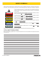
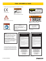
DL07
HYDRAULIC DRILL
USER MANUAL
Safety, Operation and Maintenance
© 2014 Stanley Black & Decker, Inc.
New Britain, CT 06053
U.S.A.
49234 2/2015 Ver. 10
DECLARATION OF CONFORMITY
DECLARATION OF CONFORMITY
ÜBEREINSTIMMUNGS-ERKLARUNG
DECLARATION DE CONFORMITE CEE
DECLARACION DE CONFORMIDAD
DICHIARAZIONE DI CONFORMITA
Hydraulic Tools
______________________________________________________________________
I, the undersigned:
Ich, der Unterzeichnende:
Je soussigné:
El abajo firmante:
lo sottoscritto:
Weisbeck, Andy
Surname and First names/Familiennname und Vornamen/Nom et prénom/Nombre y apellido/Cognome e nome
hereby declare that the equipment specified hereunder:
bestätige hiermit, daß erklaren Produkt genannten Werk oder Gerät:
déclare que l’équipement visé ci-dessous:
Por la presente declaro que el equipo se especifica a continuación:
Dichiaro che le apparecchiature specificate di seguito:
Drill, Hydraulic
1.
Category:
Kategorie:
Catégorie:
Categoria:
Categoria:
2.
Make/Marke/Marque/Marca/Marca
3.
Type/Typ/Type/Tipo/Tipo:
4.
Serial number of equipment:
Seriennummer des Geräts:
Numéro de série de l’équipement:
Numero de serie del equipo:
Matricola dell´attrezzatura:
Stanley
DL0755001, DL0765201
All
Has been manufactured in conformity with
Wurde hergestellt in Übereinstimmung mit
Est fabriqué conformément
Ha sido fabricado de acuerdo con
E’ stata costruita in conformitá con
Directive/Standards
Richtlinie/Standards
Directives/Normes
Directriz/Los Normas
Direttiva/Norme
No.
Nr
Numéro
No
n.
Approved body
Prüfung durch
Organisme agréé
Aprobado
Collaudato
ISO
ISO
ISO
Machinery Directive
3744:2010
20643:2005
11148-3:2010
2006/42/EC:2006
Self
Self
Self
Self
5.
Special Provisions:
None
Spezielle Bestimmungen:
Dispositions particulières:
Provisiones especiales:
Disposizioni speciali:
6.
Representative in the Union: Patrick Vervier, Stanley Dubuis 17-19, rue Jules Berthonneau-BP 3406 41034 Blois Cedex, France.
Vertreter in der Union/Représentant dans l’union/Representante en la Union/Rappresentante presso l’Unione
Done at/Ort/Fait à/Dado en/Fatto a Stanley Hydraulic Tools, Milwaukie, Oregon USA
Signature/Unterschrift/Signature/Firma/Firma
Position/Position/Fonction/Cargo/Posizione
2 ► DL07 User Manual
Director of Product Development
Date/Datum/le/Fecha/Data
1-4-11
TABLE OF CONTENTS
DECLARATION OF CONFORMITY...........................................................................................................................2
SAFETY SYMBOLS...................................................................................................................................................4
SAFETY PRECAUTIONS...........................................................................................................................................5
TOOL STICKERS & TAGS.........................................................................................................................................6
HOSE TYPE...............................................................................................................................................................7
HOSE RECOMMENDATIONS...................................................................................................................................8
FIGURE 1. TYPICAL HOSE CONNECTIONS........................................................................................................8
HTMA REQUIREMENTS............................................................................................................................................9
OPERATION.............................................................................................................................................................10
TOOL PROTECTION & CARE.................................................................................................................................12
TROUBLESHOOTING.............................................................................................................................................13
SPECIFICATIONS....................................................................................................................................................14
TORQUE AND DRILL SPEEDS...............................................................................................................................14
ACCESSORIES.......................................................................................................................................................15
DL07 PARTS ILLUSTRATION..................................................................................................................................16
DL07 PARTS LIST....................................................................................................................................................17
UNDERWATER TOOLS DEPTH GUIDELINE..........................................................................................................18
IMPORTANT
To fill out a Product Warranty Validation form, and for information on your warranty,
visit Stanleyhydraulics.com and select the Company tab, Warranty.
(NOTE: The warranty Validation record must be submitted to validate the warranty).
SERVICING: This manual contains safety, operation, and routine maintenance instructions. Stanley Hydraulic Tools
recommends that servicing of hydraulic tools, other than routine maintenance, must be performed by an authorized
and certified dealer. Please read the following warning.
WARNING
SERIOUS INJURY OR DEATH COULD RESULT FROM THE IMPROPER REPAIR OR
SERVICE OF THIS TOOL.
REPAIRS AND / OR SERVICE TO THIS TOOL MUST ONLY BE DONE BY AN
AUTHORIZED AND CERTIFIED DEALER.
For the nearest authorized and certified dealer, call Stanley Hydraulic Tools at the number listed on the back of this
manual and ask for a Customer Service Representative.
DL07 User Manual ◄ 3
SAFETY SYMBOLS
Safety symbols and signal words, as shown below, are used to emphasize all operator, maintenance and repair actions which, if not strictly followed, could result in a life-threatening situation, bodily injury or damage to equipment.
This is the safety alert symbol. It is used to alert you to potential personal injury
hazards. Obey all safety messages that follow this symbol to avoid possible
injury or death.
DANGER
This safety alert and signal word indicate an imminently hazardous situation
which, if not avoided, will result in death or serious injury.
WARNING
This safety alert and signal word indicate a potentially hazardous situation
which, if not avoided, could result in death or serious injury.
CAUTION
This safety alert and signal word indicate a potentially hazardous situation
which, if not avoided, could result in death or serious injury.
CAUTION
This signal word indicates a potentially hazardous situation which, if not avoided, may result in property damage.
NOTICE
This signal word indicates a situation which, if not avoided, will result in damage
to the equipment.
IMPORTANT
This signal word indicates a situation which, if not avoided, may result in damage to the equipment.
Always observe safety symbols. They are included for your safety and for the protection of the tool.
LOCAL SAFETY REGULATIONS
Enter any local safety regulations here. Keep these instructions in an area accessible to the operator and maintenance personnel.
4 ► DL07 User Manual
SAFETY PRECAUTIONS
Tool operators and maintenance personnel must always
comply with the safety precautions given in this manual
and on the stickers and tags attached to the tool and
hose.
•
These safety precautions are given for your safety. Review them carefully before operating the tool and before
performing general maintenance or repairs.
Always connect hoses to the tool hose couplers before energizing the hydraulic power source. Be sure
all hose connections are tight and are in good condition.
•
Do not operate the tool at oil temperatures above
140 °F/60 °C. Operation at higher temperatures can
cause higher than normal temperatures at the tool
which can result in operator discomfort.
•
Do not operate a damaged, improperly adjusted, or
incompletely assembled drill.
•
Never wear loose clothing that can get entangled in
the working parts of the tool.
•
Keep all parts of your body away from the rotating
parts. Long hair or loose clothing can become drawn
into rotating components.
•
Always use accessories that conform to the specifications given in the OPERATION section of this
manual.
•
Do not reverse impact wrench rotation direction by
changing fluid flow direction.
•
Release the trigger if the power supply has been interrupted.
•
When working near electrical conductors, always
assume that all conductors are energized and that
insulation, clothing and hoses can conduct electricity. Use hose labeled and certified as non-conductive.
•
To avoid personal injury or equipment damage, all
tool repair, maintenance and service must only be
performed by authorized and properly trained personnel.
•
Do not carry the tool by hoses.
•
Warning: Use of this tool on certain materials during
demolition could generate dust potentially containing a variety of hazardous substances such as asbestos, silica or lead. Inhalation of dust containing
these or other hazardous substances could result
in serious injury, cancer or death. Protect yourself
and those around you. Research and understand
the materials you are cutting. Follow correct safety
procedures and comply with all applicable national,
state or provisional health and safety regulations
relating to them, including, if appropriate arranging
for the safe disposal of the materials by a qualified
person.
Supervising personnel should develop additional precautions relating to the specific work area and local
safety regulations. If so, place the added precautions in
the space provided in this manual.
The model DL07 Hydraulic Drill will provide safe and
dependable service if operated in accordance with the
instructions given in this manual. Read and understand
this manual and any stickers and tags attached to the
tool and hose before operation. Failure to do so could
result in personal injury or equipment damage.
•
The operator must start in a work area without bystanders. Flying debris can cause serious injury.
•
Do not operate the tool unless thoroughly trained
or under the supervision of an instructor. Establish
a training program for all operators to ensure safe
operation.
•
Always wear safety equipment such as goggles, ear
and head protection, and safety shoes at all times
when operating the tool. Use gloves and aprons
when necessary.
•
The operator must be familiar with all prohibited
work areas such as excessive slopes and dangerous terrain conditions.
•
Maintain proper footing and balance at all times.
•
Do not inspect or clean the tool while the hydraulic
power source is connected. Accidental engagement
of the tool can cause serious injury.
DL07 User Manual ◄ 5
TOOL STICKERS & TAGS
Please refer to the parts illustration for location of stickers.
Stanley Hydraulic Tools
3810 SE Naef Road
Milwaukie, Oregon USA
4-12 GPM/15-45 LPM
26-45 LPM / 7-12 GPM
2000 PSI
/ 140/ 2000
BARPSI
140 BAR
Model No.
DL07
IW16
28322
CE STICKER (CE)
58862
PRESSURE WARNING STICKER
60807
DL07 MODEL STICKER
WARNING
D
30 LPM @ 138 B AR
EHTMA CATEGORY
11207
CIRCUIT TYPE D STICKER (CE)
58864
ELECTRICAL WARNING STICKER
OC/CC
28788
MANUAL STICKER (CE)
FOR USE ON OPEN CENTER AND
CLOSED CENTER HYDRAULIC
SYSTEMS. “SET FOR PROPER SYSTEM
BEFORE USE”
RATED NO-LOAD SPEED
1000 RPM AT
8 GPM/30 LPM
29148
RPM STICKER
11354
OC/CC STICKER
NOTE
THE INFORMATION LISTED ON
THE STICKERS SHOWN, MUST
BE LEGIBLE AT ALL TIMES.
REPLACE DECALS IF THEY
BECOME WORN OR DAMAGED.
REPLACEMENTS ARE AVAILABLE
FROM YOUR LOCAL STANLEY
DISTRIBUTOR.
D A N G E R
1.
FAILURE TO USE HYDRAULIC HOSE LABELED AND CERTIFIED AS NON-CONDUCTIVE WHEN USING HYDRAULIC
TOOLS ON OR NEAR ELECTRICAL LINES MAY RESULT IN
DEATH OR SERIOUS INJURY.
BEFORE USING HOSE LABELED AND CERTIFIED AS NONCONDUCTIVE ON OR NEAR ELECTRIC LINES BE SURE THE
HOSE IS MAINTAINED AS NON-CONDUCTIVE. THE HOSE
SHOULD BE REGULARLY TESTED FOR ELECTRIC CURRENT
LEAKAGE IN ACCORDANCE WITH YOUR SAFETY DEPARTMENT INSTRUCTIONS.
2.
A HYDRAULIC LEAK OR BURST MAY CAUSE OIL INJECTION
INTO THE BODY OR CAUSE OTHER SEVERE PERSONAL
INJURY.
A.
DO NOT EXCEED SPECIFIED FLOW AND PRESSURE
FOR THIS TOOL. EXCESS FLOW OR PRESSURE MAY
CAUSE A LEAK OR BURST.
B.
DO NOT EXCEED RATED WORKING PRESSURE OF
HYDRAULIC HOSE USED WITH THIS TOOL. EXCESS
PRESSURE MAY CAUSE A LEAK OR BURST.
C. CHECK TOOL HOSE COUPLERS AND CONNECTORS
DAILY FOR LEAKS. DO NOT FEEL FOR LEAKS WITH
YOUR HANDS. CONTACT WITH A LEAK MAY RESULT
IN SEVERE PERSONAL INJURY.
The safety tag (P/N 15875) at right is attached
to the tool when shipped from the factory. Read
and understand the safety instructions listed on
this tag before removal. We suggest you retain
this tag and attach it to the tool when not in use.
D A N G E R
D. DO NOT LIFT OR CARRY TOOL BY THE HOSES. DO
NOT ABUSE HOSE. DO NOT USE KINKED, TORN OR
DAMAGED HOSE.
3.
MAKE SURE HYDRAULIC HOSES ARE PROPERLY CONNECTED TO THE TOOL BEFORE PRESSURING SYSTEM.
SYSTEM PRESSURE HOSE MUST ALWAYS BE CONNECTED TO TOOL “IN” PORT. SYSTEM RETURN HOSE
MUST ALWAYS BE CONNECTED TO TOOL “OUT” PORT.
REVERSING CONNECTIONS MAY CAUSE REVERSE
TOOL OPERATION WHICH CAN RESULT IN SEVERE
PERSONAL INJURY.
4.
DO NOT CONNECT OPEN-CENTER TOOLS TO CLOSEDCENTER HYDRAULIC SYSTEMS. THIS MAY RESULT IN
LOSS OF OTHER HYDRAULIC FUNCTIONS POWERED BY
THE SAME SYSTEM AND/OR SEVERE PERSONAL INJURY.
5.
BYSTANDERS MAY BE INJURED IN YOUR WORK AREA.
KEEP BYSTANDERS CLEAR OF YOUR WORK AREA.
6.
WEAR HEARING, EYE, FOOT, HAND AND HEAD PROTECTION.
7.
TO AVOID PERSONAL INJURY OR EQUIPMENT DAMAGE,
ALL TOOL REPAIR MAINTENANCE AND SERVICE MUST
ONLY BE PERFORMED BY AUTHORIZED AND PROPERLY
TRAINED PERSONNEL.
I M P O R T A N T
I M P O R T A N T
READ OPERATION MANUAL AND
SAFETY INSTRUCTIONS FOR THIS
TOOL BEFORE USING IT.
READ OPERATION MANUAL AND
SAFETY INSTRUCTIONS FOR THIS
TOOL BEFORE USING IT.
USE ONLY PARTS AND REPAIR
PROCEDURES APPROVED BY
STANLEY AND DESCRIBED IN THE
OPERATION MANUAL.
USE ONLY PARTS AND REPAIR
PROCEDURES APPROVED BY
STANLEY AND DESCRIBED IN THE
OPERATION MANUAL.
TAG TO BE REMOVED ONLY BY
TOOL OPERATOR.
TAG TO BE REMOVED ONLY BY
TOOL OPERATOR.
SEE OTHER SIDE
SEE OTHER SIDE
SAFETY TAG P/N 15875 (Shown smaller then actual size)
6 ► DL07 User Manual
HOSE TYPES
The rated working pressure of the hydraulic hose must be equal to or higher than the relief valve setting on the hydraulic system. There are three types of hydraulic hose that meet this requirement and are authorized for use with
Stanley Hydraulic Tools. They are:
Certified non-conductive — constructed of thermoplastic or synthetic rubber inner tube, synthetic fiber braid
reinforcement, and weather resistant thermoplastic or synthetic rubber cover. Hose labeled certified nonconductive is the only hose authorized for use near electrical conductors.
Wire-braided (conductive) — constructed of synthetic rubber inner tube, single or double wire braid reinforcement, and weather resistant synthetic rubber cover. This hose is conductive and must never be used near
electrical conductors.
Fabric-braided (not certified or labeled non-conductive) — constructed of thermoplastic or synthetic rubber inner tube, synthetic fiber braid reinforcement, and weather resistant thermoplastic or synthetic rubber cover. This
hose is not certified non-conductive and must never be used near electrical conductors.
HOSE SAFETY TAGS
To help ensure your safety, the following DANGER tags are attached to all hose purchased from Stanley Hydraulic
Tools. DO NOT REMOVE THESE TAGS.
If the information on a tag is illegible because of wear or damage, replace the tag immediately. A new tag may be
obtained from your Stanley Distributor.
D A N G E R
D A N G E R
1.
FAILURE TO USE HYDRAULIC HOSE LABELED AND CERTIFIED AS NON-CONDUCTIVE
WHEN USING HYDRAULIC TOOLS ON OR NEAR ELECTRIC LINES MAY RESULT IN
DEATH OR SERIOUS INJURY.
FOR PROPER AND SAFE OPERATION MAKE SURE THAT YOU HAVE BEEN PROPERLY TRAINED IN CORRECT PROCEDURES REQUIRED FOR WORK ON OR AROUND
ELECTRIC LINES.
2.
BEFORE USING HYDRAULIC HOSE LABELED AND CERTIFIED AS NON-CONDUCTIVE
ON OR NEAR ELECTRIC LINES. WIPE THE ENTIRE LENGTH OF THE HOSE AND FITTING WITH A CLEAN DRY ABSORBENT CLOTH TO REMOVE DIRT AND MOISTURE AND
TEST HOSE FOR MAXIMUM ALLOWABLE CURRENT LEAKAGE IN ACCORDANCE WITH
SAFETY DEPARTMENT INSTRUCTIONS.
3.
DO NOT EXCEED HOSE WORKING PRESSURE OR ABUSE HOSE. IMPROPER USE
OR HANDLING OF HOSE COULD RESULT IN BURST OR OTHER HOSE FAILURE.
KEEP HOSE AS FAR AWAY AS POSSIBLE FROM BODY AND DO NOT PERMIT DIRECT
CONTACT DURING USE. CONTACT AT THE BURST CAN CAUSE BODILY INJECTION
AND SEVERE PERSONAL INJURY.
4.
HANDLE AND ROUTE HOSE CAREFULLY TO AVOID KINKING, ABRASION, CUTTING, OR
CONTACT WITH HIGH TEMPERATURE SURFACES. DO NOT USE IF KINKED. DO NOT
USE HOSE TO PULL OR LIFT TOOLS, POWER UNITS, ETC.
5.
CHECK ENTIRE HOSE FOR CUTS CRACKS LEAKS ABRASIONS, BULGES, OR DAMAGE TO COUPLINGS IF ANY OF THESE CONDITIONS EXIST, REPLACE THE HOSE
IMMEDIATELY. NEVER USE TAPE OR ANY DEVICE TO ATTEMPT TO MEND THE HOSE.
6.
AFTER EACH USE STORE IN A CLEAN DRY AREA.
SEE OTHER SIDE
SIDE 1
SEE OTHER SIDE
(Shown smaller than actual size)
DO NOT REMOVE THIS TAG
DO NOT REMOVE THIS TAG
THE TAG SHOWN BELOW IS ATTACHED TO “CERTIFIED NON-CONDUCTIVE” HOSE
SIDE 2
D A N G E R
D A N G E R
1.
DO NOT USE THIS HYDRAULIC HOSE ON OR NEAR ELECTRIC LINES. THIS HOSE IS
NOT LABELED OR CERTIFIED AS NON-CONDUCTIVE. USING THIS HOSE ON OR NEAR
ELECTRICAL LINES MAY RESULT IN DEATH OR SERIOUS INJURY.
5.
CHECK ENTIRE HOSE FOR CUTS CRACKS LEAKS ABRASIONS, BULGES, OR DAMAGE TO
COUPLINGS IF ANY OF THESE CONDITIONS EXIST, REPLACE THE HOSE IMMEDIATELY.
NEVER USE TAPE OR ANY DEVICE TO ATTEMPT TO MEND THE HOSE.
2.
FOR PROPER AND SAFE OPERATION MAKE SURE THAT YOU HAVE BEEN PROPERLY
TRAINED IN CORRECT PROCEDURES REQUIRED FOR WORK ON OR AROUND ELECTRIC LINES.
6.
AFTER EACH USE STORE IN A CLEAN DRY AREA.
3.
DO NOT EXCEED HOSE WORKING PRESSURE OR ABUSE HOSE. IMPROPER USE OR
HANDLING OF HOSE COULD RESULT IN BURST OR OTHER HOSE FAILURE. KEEP HOSE
AS FAR AWAY AS POSSIBLE FROM BODY AND DO NOT PERMIT DIRECT CONTACT
DURING USE. CONTACT AT THE BURST CAN CAUSE BODILY INJECTION AND SEVERE
PERSONAL INJURY.
4.
HANDLE AND ROUTE HOSE CAREFULLY TO AVOID KINKING, CUTTING, OR CONTACT
WITH HIGH TEMPERATURE SURFACES. DO NOT USE IF KINKED. DO NOT USE HOSE TO
PULL OR LIFT TOOLS, POWER UNITS, ETC.
DO NOT REMOVE THIS TAG
DO NOT REMOVE THIS TAG
THE TAG SHOWN BELOW IS ATTACHED TO “CONDUCTIVE” HOSE.
SEE OTHER SIDE
SEE OTHER SIDE
SIDE 1
SIDE 2
(Shown smaller than actual size)
DL07 User Manual ◄ 7
8 ► DL07 User Manual
All hydraulic hose must meet or exceed
specifications as set forth by SAE J517.
All hydraulic hose must have at least a rated
minimum working pressure equal to the maximum hydraulic system relief valve setting.
This chart is intended to be used for hydraulic
tool applications only based on Stanley Hydraulic Tools tool operating requirements and
should not be used for any other applications.
The chart to the right shows recommended
minimum hose diameters for various hose
lengths based on gallons per minute (gpm)/
liters per minute (lpm). These recommendations are intended to keep return line pressure
(back pressure) to a minimum acceptable level to ensure maximum tool performance.
Tool to Hydraulic Circuit Hose
Recommendations
15-34
MM
Inside Diameter
INCH
USE
(Press/Return)
PSI
up to 10
up to 3
3/8
10
Both
2250
49-60
13-16
FLOW >>>
RETURN
<<< FLOW
PRESSURE
26-100
up to 25
100-200
51-100
up to 50
100-300
51-100
up to 50
26-100
up to 25
8-30
up to 8
30-60
15-30
up to 15
30-90
15-30
up to 15
7.5-30
up to 7.5
Figure 1. Typical Hose Connections
49-60
38-49
10-13
13-16
19-40
5-10.5
38-49
19-40
5-10.5
10-13
19-40
5-10.5
38-49
15-23
10-13
15-23
4-6
19
25.4
16
19
19
25.4
5/8
3/4
3/4
1
19
3/4
1
16
3/4
16
19
3/4
5/8
16
5/8
5/8
16
13
13
10
5/8
1/2
1/2
3/8
Return
Pressure
Return
Pressure
Return
Pressure
Return
Pressure
Both
Return
Pressure
Both
Both
Both
Both
2500
2500
2500
2500
2500
2500
2500
2500
2500
2500
2500
2500
2500
2500
2500
175
175
175
175
175
175
175
175
175
175
175
175
175
175
175
155
BAR
Min. Working Pressure
Certified Non-Conductive Hose - Fiber Braid - for Utility Bucket Trucks
METERS
Hose Lengths
FEET
Conductive Hose - Wire Braid or Fiber Braid -DO NOT USE NEAR ELECTRICAL CONDUCTORS
4-6
4-9
LPM
Oil Flow
GPM
HOSE RECOMMENDATIONS
HTMA / EHTMA REQUIREMENTS
HTMA / EHTMA REQUIREMENTS
HTMA
HYDRAULIC SYSTEM REQUIREMENTS
TYPE I
Nominal Operating Pressure
(at the power supply outlet)
4-6 gpm
(15-23 lpm)
1500 psi
(103 bar)
TOOL TYPE
TYPE II
TYPE RR
7-9 gpm
(26-34 lpm)
1500 psi
(103 bar)
9-10.5 gpm
(34-40 lpm)
1500 psi
(103 bar)
System relief valve setting
(at the power supply outlet)
2100-2250 psi
(145-155 bar)
2100-2250 psi
(145-155 bar)
2200-2300 psi
(152-159 bar)
2100-2250 psi
(145-155 bar)
Maximum back pressure
(at tool end of the return hose)
250 psi
(17 bar)
250 psi
(17 bar)
250 psi
(17 bar)
250 psi
(17 bar)
Measured at a max. fluid viscosity of:
(at min. operating temperature)
400 ssu*
400 ssu*
400 ssu*
400 ssu*
(82 centistokes) (82 centistokes) (82 centistokes) (82 centistokes)
Temperature: Sufficient heat rejection
capacity to limit max. fluid temperature to:
(at max. expected ambient temperature)
140° F
(60° C)
Flow Range
140° F
(60° C)
140° F
(60° C)
TYPE III
11-13 gpm
(42-49 lpm)
1500 psi
(103 bar)
140° F
(60° C)
3 hp
5 hp
6 hp
7 hp
Min. cooling capacity at a temperature
(2.24 kW)
(3.73 kW)
(5.22 kW)
(4.47 kW)
difference of between ambient and fluid
40° F
40° F
40° F
40° F
temps
(22° C)
(22° C)
(22° C)
(22° C)
NOTE:
Do not operate the tool at oil temperatures above 140° F (60° C). Operation at higher temperatures can cause operator
discomfort at the tool.
Filter
Min. full-flow filtration
Sized for flow of at least:
(For cold temp. startup and max.
dirt-holding capacity)
25 microns
30 gpm
(114 lpm)
Hydraulic fluid Petroleum based
(premium grade, anti-wear, non-conductive)
Viscosity (at min. and max. operating temps)
100-400 ssu*
25 microns
30 gpm
(114 lpm)
25 microns
30 gpm
(114 lpm)
100-400 ssu*
100-400 ssu*
(20-82 centistokes)
25 microns
30 gpm
(114 lpm)
100-400 ssu*
NOTE:
When choosing hydraulic fluid, the expected oil temperature extremes that will be experienced in service determine the
most suitable temperature viscosity characteristics. Hydraulic fluids with a viscosity index over 140 will meet the requirements
over a wide range of operating temperatures.
*SSU = Saybolt Seconds Universal
EHTMA
HYDRAULIC SYSTEM
REQUIREMENTS
CLASSIFICATION
B
C
D
Nominal Operating Pressure
(at the power supply outlet)
3.5-4.3 gpm
(13.5-16.5 lpm)
1870 psi
(129 bar)
4.7-5.8 gpm
(18-22 lpm)
1500 psi
(103 bar)
7.1-8.7 gpm
(27-33 lpm)
1500 psi
(103 bar)
9.5-11.6 gpm
(36-44 lpm)
1500 psi
(103 bar)
11.8-14.5 gpm
(45-55 lpm)
1500 psi
(103 bar)
System relief valve setting
(at the power supply outlet)
2495 psi
(172 bar)
2000 psi
(138 bar)
2000 psi
(138 bar)
2000 psi
(138 bar)
2000 psi
(138 bar)
Flow Range
NOTE: These are general hydraulic system requirements. See tool specification page for tool specific requirements
DL07 User Manual ◄ 9
OPERATION
PREOPERATION PROCEDURES
CHECK POWER SOURCE
1. Using a calibrated flow meter and pressure gauge,
check that the hydraulic power source develops a
flow of 4-12 gpm/15-45 lpm at 1000-2000 psi/70140 bar.
2. Make certain that the hydraulic power source is
equipped with a relief valve set to open at 2100
psi/145 bar minimum.
CONNECT HOSES
1. Wipe all hose couplers with a clean lint-free cloth
before making connections.
2. Connect hoses from the hydraulic power supply to
the tool quick disconnects. It is good practice to connect the return hose first and disconnect it last to
minimize or avoid trapped pressure within the drill.
3. Observe the arrow on hose couplers to ensure that
the flow is in the proper direction. The male coupler
on the circuit hose end is the supply (pressure) coupler.
4. Make sure the circuit PRESSURE (male quick disconnect) hose is connected to the port at the back of
the drill handle. The circuit RETURN hose (female
quick disconnect) is connected to the port closest to
the trigger.
FOR CLOSED-CENTER OPERATION:
Using a 3/16 in. hex, reach through the hole in the spring
cap and turn the selector screw fully clockwise. When
the selector screw bottoms. Closed-center operation is
now selected.
CAUTION
To prevent damage to the retaining ring, do not
attempt to force the selector screw counter-clockwise
beyond the point of initial resistance.
Reinstall the hex plug. Failure to install the plug may introduce contaminants to the spool bore resulting in replacement of the valve spool and main housing.
DRILL OPERATION
1. Observe all safety precautions.
2. Place the selected drill bit fully into the chuck. Center the bit and tighten the chuck using the key provided. Remove the key and store away from the drill.
3. Momentarily press the trigger to ensure that the drill
bit rotates clockwise and runs true.
4. Select a work position that gives secure footing and
balance while operating the drill.
5. Move the hydraulic circuit control valve to the ON
position to direct hydraulic flow to the drill.
5. Press the drill against the work and squeeze the trigger.
NOTE:
The drilling method used is determined by the material
being drilled and the size and depth requirements of the
hole.
If uncoupled hoses are left in the sun, pressure increase inside the hose may result in making them
difficult to connect. Whenever possible, connect the
free ends of the hoses together.
OPEN-CENTER (OC) OR CLOSED-CENTER
(CC) OPERATION
The DL07 can be configured to run on OC or CC circuits.
Brittle material such as rock, brick or concrete can be
drilled efficiently when the bit is caused to strike (hammer) the hole bottom to break up the material. Without
hammering, the rotating bit will only grind down and become dull. The Stanley HD08 should be used for this
application.
1. Determine the system type.
2. Remove the hex plug (81) from the spring cap.
FOR OPEN-CENTER OPERATION:
Using a 3/16 in. hex, reach through the hole in the spring
cap and turn the selector screw counter-clockwise until
meeting resistance (from the retaining ring). Turn the selector clockwise and then counter-clockwise to be sure
the selector is being stopped by the retaining ring. Do
not force the selector screw. Open-center operation is
now selected.
10 ► DL07 User Manual
ASSIST HANDLE
1. The assist handle (Item-22) can be installed on
either side of the DL07 to accommodate the user
preference. Install the handle into the 3/8-18NPT
hole located on the left or right side of (Item 69) gear
housing.
OPERATION
Ductile material such as metal or wood is drilled efficiently when a steady down force is applied to the drill
center to cause the bit to slice chips of material from the
hole bottom. When drilling in metal, use a cutting lubricant to prolong bit life and reduce the amount of force
required to drill effectively.
Large drill holes are more productively created from
small drill holes. Drill bits are incrementally selected to
enlarge the hole until the desired hole size is obtained.
Each bit selected must always be too large to thread and
jam into an existing hole; otherwise the bit may break
and endanger the operator.
COLD WEATHER OPERATION
If the wrench is to be used during cold weather, preheat
the hydraulic fluid at low engine speed. When using the
normally recommended fluids, fluid temperature should
be at or above 50 °F/10 °C (400 ssu/82 centistokes) before use.
Damage to the hydraulic system or wrench can result
from use with fluid that is too viscous or too thick.
DL07 User Manual ◄ 11
TOOL PROTECTION & CARE
NOTICE
In addition to the Safety Precautions found in
this manual, observe the following for equipment
protection and care.
•
Make sure all couplers are wiped clean before connection.
•
The hydraulic circuit control valve must be in the
“OFF” position when coupling or uncoupling hydraulic tools. Failure to do so may result in damage to
the quick couplers and cause overheating of the hydraulic system.
•
Do not exceed the rated flow (see Specifications) in
this manual for correct flow rate and model number.
Rapid failure of the internal seals may result.
•
Always keep critical tool markings, such as warning
stickers and tags legible.
•
Tool repair should be performed by experienced
personnel only.
•
Always store the tool in a clean dry space, safe from
damage or pilferage.
•
•
Make sure the circuit PRESSURE hose (with male
quick disconnect) is connected to the “IN” port. The
circuit RETURN hose (with female quick disconnect)
is connected to the opposite port. Do not reverse circuit flow. This can cause damage to internal seals.
Make certain that the recommended relief valves
are installed in the pressure side of the system.
•
Do not use the tool for applications for which it was
not intended.
•
Always replace hoses, couplings and other parts
with replacement parts recommended by Stanley
Hydraulic Tools. Supply hoses must have a minimum working pressure rating of 2500 psi/172 bar.
12 ► DL07 User Manual
TROUBLESHOOTING
If symptoms of poor performance develop, the following chart can be used as a guide to correct the problem. When
diagnosing faults in operation of the wrench, always check that the hydraulic power source is supplying the correct
hydraulic flow and pressure to the tool as listed in the following table. Use a flow meter known to be accurate. Check
the flow with the hydraulic fluid temperature at least 80 °F/27 °C.
PROBLEM
Tool will not start.
CAUSE
Power not being supplied.
SOLUTION
Check to make certain that both hoses are
connected.
Turn hydraulic circuit control valve ON.
Low drilling torque.
Defective quick disconnects.
Check each quick disconnect.
Relief valve set too low.
Set relief valve at 2100 psi/145 bar.
Fluid restriction in hose or valve. Locate and remove restriction.
Excess flow and pressure loss.
Use correct fluid.
Fluid not warmed up. Preheat system.
Hoses too long for hose ID. Use shorter
hose.
Hose ID too small for hose length. Use
larger ID hose.
Low tool speed.
Fluid flow rate is too low.
Check circuit flow rate.
High tool speed.
Fluid flow rate is excessive.
Check circuit flow rate. Add proper flow
control valve or reduce the pump RPM.
Oil leaks around gear housing.
Hydraulic pressure and return Correct hose connections. Pressure should
hoses reversed.
be to the handle port away from the trigger,
return is near the trigger, then replace the
main shaft oil seal.
Oil gets hot, power unit working Open-center tool on a closed- Use tools to match circuit.
hard.
center circuit or vice-versa.
Oil leaks at reversing spool.
Circuit relief set too low.
Adjust relief valve to 2100 psi/145 bar.
Too much oil going through tool.
Adjust flow for 12 gpm/45 lpm maximum or
less.
Damaged O-rings.
Replace as required.
Wrong hydraulic fluid. Circuit too Refer to Operation section for correct fluid/
hot.
circuit specifications.
Oil leak at motor cap face.
Fasteners loose.
Refer to Service Manual.
Face O-ring worn or missing.
Replace as required.
Motor cap/main housing dam- Replace as required.
aged.
DL07 User Manual ◄ 13
SPECIFICATIONS
Drive Size.............................................................................................................. 1/2 inch / 1.3 cm 3-Jaw Adjustable
5/8 -16 THD Chuck
Drill Torque.......................................................................................................20 ft lbs / 27 Nm at 2000 psi / 140 bar
Drill Speed........................................................................................................................1000 rpm at 8 gpm / 30 lpm
RPM Range..................................................................................................................................................350–1500
Weight......................................................................................................................................................8 lbs / 3.6 kg
Overall Length.....................................................................................................................................9 inch / 22.9 cm
Width.....................................................................................................................................................3.5 inch / 9 cm
Motor................................................................................................................................................................Integral
Pressure Range.............................................................................................................. 1000–2000 psi / 70–140 bar
Flow Range.................................................................................................................................... 4–12 gpm / 30 lpm
Optimum Flow................................................................................................................................ 8 gpm / 15–34 lpm
System Type....................................................................................Open and Closed Center, HTMA Type I, II and III
Porting....................................................................................................................................................-8 SAE O-ring
Output Torque.................................................................................................................................500 ft lbs / 675 Nm
Connect Size and Type..................................................................................................... 3/8 inch NPT Male Adapter
TORQUE AND DRILL SPEEDS
TORQUE
HYDRAULIC FLOW
DRILL SPEED
4 ft lbs @ 500 psi / .5 Nm @ 35 bar
3 gpm / 11.3 lpm
350 rpm
9 ft lbs @ 1000 psi / 1.2 Nm @ 70 bar
4 gpm / 15 lpm
475 rpm
14 ft lbs @ 1500 psi / 1.9 Nm @ 105 bar
6 gpm / 23 lpm
750 rpm
19 ft lbs @ 2000 psi / 2.6 Nm @ 140 bar
8 gpm / 30 lpm
10 gpm / 38 lpm
1000 rpm
1250 rpm
SOUND AND VIBRATION DECLARATION
Test conducted on DL0755001 operated at standard 5 gpm input
Measured A-weighted sound power level, Lwa (ref. 1pW) in decibels
Uncertainty, Kwa, in decibels
Measured A-weighted sound pressure level, Lpa (ref. 20 µPa) at operator’s position, in decibels
Uncertainty, Kpa, in decibels
87.6 dBA
3 dBA
79.6 dBA
3 dBA
Values determined according to noise test code given in ISO 15744, using the basic standard
ISO 3744
NOTE: The sum of a measured noise emission value and its associated uncertainty represents
an upper boundary of the range of values which is likely to occur in measurements.
Declared vibration emission value in accordance with EN 12096
Measured vibration emission value: a
Uncertainty: K
Values determined according to ISO 8662-1, ISO 5349-1,2
14 ► DL07 User Manual
1.4 m/sec²
0.35 m/sec²
ACCESSORIES
DESCRIPTION
PART NUMBER
WOOD AUGER BITS, 5/8 INCH HEX
9/16 inch dia × 18 inch Carbide Tipped Auger Bit (22 inch OAL).......................................................................27845
13/16 inch dia × 18 inch Carbide Tipped Auger Bit (22 inch OAL).....................................................................27847
WOOD AUGER BITS, 7/16 INCH HEX
9/16 inch dia × 8 inch Carbide Tipped Auger Bit (12 inch OAL).........................................................................27850
11/16 inch dia × 8 inch Carbide Tipped Auger Bit (12 inch OAL)........................................................................27851
13/16 inch dia × 8 inch Carbide Tipped Auger Bit (12 inch OAL).......................................................................27852
15/16 inch dia × 8 inch Carbide Tipped Auger Bit (12 inch OAL).......................................................................27853
1-1/16 inch dia × 8 inch Carbide Tipped Auger Bit (12 inch OAL)......................................................................27854
9/16 inch dia × 12 inch Carbide Tipped Auger Bit (16 inch OAL).......................................................................27855
11/16 inch dia × 12 inch Carbide Tipped Auger Bit (16 inch OAL)......................................................................27856
13/16 inch dia × 12 inch Carbide Tipped Auger Bit (16 inch OAL).....................................................................27857
15/16 inch dia × 12 inch Carbide Tipped Auger Bit (16 inch OAL).....................................................................27858
1-1/16 inch dia × 12 inch Carbide Tipped Auger Bit (16 inch OAL)....................................................................27859
9/16 inch dia × 18 inch Carbide Tipped Auger Bit (22 inch OAL).......................................................................27860
11/16 inch dia × 18 inch Carbide Tipped Auger Bit (22 inch OAL)......................................................................27861
13/16 inch dia × 18 inch Carbide Tipped Auger Bit (22 inch OAL).....................................................................27862
15/16 inch dia × 18 inch Carbide Tipped Auger Bit (22 inch OAL).....................................................................27863
1-1/16 inch dia × 18 inch Carbide Tipped Auger Bit (22 inch OAL)....................................................................27864
13/16 inch dia × 36 inch Carbide Tipped Auger Bit (48 inch OAL).....................................................................27869
DL07 User Manual ◄ 15
16 ► DL07 User Manual
31
33
32
58
53
20
80
38
71
69
55
35
34
4
8
30
32
16
28
22
44
61
25
39
24
78
4
70
21
42
19
77
13
36
57
7
23
76
14
26
1
29
15
5
68
47
27
17
59
43
73
2
50
10
18
1
72
9
64
60
45
37
62
63
65
40
15
74
67
79
54
66
81
6
46
3
52
11
41
12
49
75
56
48
DL07 PARTS ILLUSTRATION
DL07 PARTS LIST
ITEM
P/N
QTY
DESCRIPTION
ITEM
P/N
QTY
DESCRIPTION
1
00026
1
O-RING
49
03973
1
2
00175
2
O-RING
3/8 NPT FLUSHFACE COUPLER NOSE
PART OF SET 03971 (PARKER) OR 47437
(AEROQUIP) FOR DL07552S, 552SUP, 572S
3
00231
6
LOCKWASHER
50
24271
1
MAIN SHAFT
4
00354
1
O-RING
51
25610
1
5
00563
1
ROLL PIN
RAILROAD HELP DESK STICKER
(DL07552S, 552SUP, 572S ONLY)
6
00713
2
DOWEL PIN
52
28323
2
CE STICKER (DL0755001 ONLY)
7
00717
1
O-RING
53
60807
1
DL07 MODEL NUMBER STICKER
8
62229
2
CAPSCREW
54
28788
2
MANUAL STICKER
9
01262
1
O-RING
55
29148
1
RPM STICKER (DL0755001 ONLY)
10
01604
1
O-RING
56
29149
1
ROTATION DIRECTION STICKER
(DL0755001 ONLY)
11
02324
1
CAP AND PLUG, 1/2 INCH
57
38676
1
DEPTH GAUGE ROD (DL07552S, 572S ONLY)
12
03288
1
CAP AND PLUG, 3/8 INCH
58
38685
1
THUMB SCREW (DL07552S, 572S ONLY)
13
03364
1
O-RING
59
48986
1
VALVE SPOOL ASSY
14
05206
2
BUSHING
60
—
—
NO ITEM
15
05207
2
BUSHING
61
49139
1
SEAL WIPER
16
06635
1
RETAINING RING
62
2
17
07224
2
BACKUP RING
56725
66727
HOSE ASSY (PARKER)
HOSE ASSY (AEROQUIP)
18
07626
1
O-RING
63
56747
2
SEAL WIPER
O-RING
64
56749
2
SEAL CAP
NYLOCK NUT
65
56757
2
END CAP
ROLL PIN
66
56758
1
SPRING CAP
56764
2
RETAINING RING
19
20
21
07627
07724
07970
1
1
1
22
08130
1
HANDLE
67
23
08161
2
PLANET SHAFT
68
56765
1
REVERSING SPOOL
24
08162
1
SHAFT KEEPER
69
58403
1
GEAR HOUSING MACHINING
70
58462
1
RELIEF CARTRIDGE PLUG ASSY
(INCL ITEMS 7 AND 13)
71
58635
1
SEAL GASKET
72
58856
1
3/8 FLUSHFACE COUPLER BODY 1/2 INCH
MALE SAE
(PART OF SET 58718 FOR DL07550, 55001,
652 ONLY)
73
58857
1
3/8 FLUSHFACE COUPLER NOSE 1/2 INCH
MALE SAE
(PART OF SET 58718 FOR DL07550, 5501, 652
ONLY)
74
58862
1
PRESSURE WARNING STICKER
(DL07550, 652, 552S, 552SUP, 572S ONLY)
75
58864
1
ELECTRICAL WARNING STICKER
(DL07550, 652, 552S, 552SUP, 572S ONLY)
25
08163
1
BEARING KEEPER
26
08165
2
PLANET GEAR ASSY
27
08166
1
RING GEAR
28
08175
1
BALL BEARING
29
08440
1
RETAINING RING
30
09621
1
SHAFT SEAL
31
62228
3
CAPSCREW
32
09623
5
LOCKWASHER
33
09624
27628
1
DRILL CHUCK, 1/2 INCH
DRILL CHUCK, 5/8 INCH
34
09687
1
CAPSCREW
35
09778
1
SEAL NUT
76
59049
1
MAIN HOUSING ASSY (INCL ITEMS 15, 42)
36
09779
1
OUTPUT SHAFT
77
60677
1
TRIGGER CASTING
37
11207
1
CIRCUIT TYPE D STICKER
78
60678
1
TRIGGER MOUNT CASTING
38
11354
1
OC/CC STICKER
79
65480
1
SPRING
39
13995
1
BACKUP RING
80
60710
1
TRIGGER GUARD
40
—
—
NO ITEM
81
350041
1
HOLLOW HEX PLUG
41
18206
6
CAPSCREW
42
20758
1
BUSHING
60792
1
SEAL KIT
43
20760
1
BUSHING
44
20767
1
SEAL BACKUP WASHER
45
20769
1
IDLER GEAR ASSY
46
20770
1
MOTOR CAP ASSY (INCLUDES 1 BUSHING
ITEM 15 & 2 DOWEL PINS ITEM 6)
47
20782
1
IDLER SHAFT
48
03972
1
3/8 NPT FLUSHFACE COUPLER BODY
PART OF SET 03971 (PARKER) OR 47436
(AEROQUIP) FOR DL07552S, 552SUP, 572S
DL07 User Manual ◄ 17
UNDERWATER TOOLS DEPTH GUIDELINE
CAUTION
DO NOT USE HYDRAULIC TOOLS UNDERWATER THAT ARE NOT DESIGNATED AS
AN “UNDERWATER” MODEL, OR THIS
WILL RESULT IN DAMAGE TO THE TOOL.
Operation Overview
Percussive
Tools: Breakers,
Hammer Drills and
Chipping Hammers
Diver
UNDERWATER MODELS ONLY
The types of tools are percussive and rotational,
each with different characteristics allowing for different depth operation. With percussive tools, the
nitrogen accumulator PSI must counter the increase in ambient pressure found at lower depths.
Since there is a maximum PSI for percussive tools
they are limited to certain depths. Rotational tools
do not have accumulators and thus capable of
deeper depths.
The methods are broken into diver operated or
remote operated vehicle (ROV). ROV's can reach
lower depths and with an on-board hydraulic
power source that is depth compensated, can
operate hydraulic tools at depths of thousands of
feet. ROV operation is still limited to the tool, for
example a percussive tool has the same depth
limitation whether ROV or diver operated.
18 ► DL07 User Manual
ROV
For underwater hydraulic tools the applications are
broken down into four quadrants depending on
type of tool and method of operation.
Max Depth: 500' limitations due to
accumulator PSI
max (increase 40
PSI for every 100')
Tools: Breakers,
Hammer Drills and
Chipping Hammers
Max Depth: 500' limitations due to
accumulator PSI
max (increase 40
PSI for every 100')
Rotational
Tools: Grinders,
Saws, Chain Saws
Max Depth: 1000' Reference hose
sizing guide below
Tools: Grinders,
Saws, Chain Saws
Max Depth: 1000' Reference hose
sizing guide below
Recommended Hose Diameters
Depth (ft)
100
300
600
1000
8 GPM
5/8”
3/4”
1”
1”
12 GPM
5/8”
1”
1”
1-1/4”
NOTES
DL07 User Manual ◄ 19
Stanley Hydraulic Tools
3810 SE Naef Road
Milwaukie, Oregon 97267-5698 USA
(503) 659-5660 / Fax (503) 652-1780
www.stanleyhydraulics.com