1
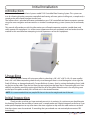
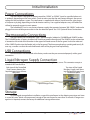
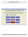
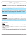
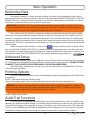
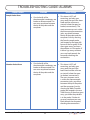
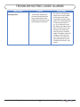
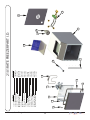
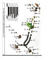
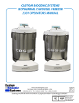
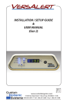
CUSTOM BIOGENIC SYSTEMS 2101 CONTROLLED RATE FREEZER SET-UP & TECHNICAL MANUAL Custom BioGenic Systems www.custombiogenics.com 150 Shafer Drive w Romeo, MI 48065 w USA 1.800.523.0072 w Tel: 1.586.331.2600 w Fax: 1.586.331.2588 Leading the World with Innovative Cryopreservation Technology Solutions IMPORTANT INFORMATION We at Custom Biogenic Systems are proud of our work, and appreciate your purchase of this product. With proper care, this equipment will be trouble-free for many years to come. Before setting up and using your new cryogenic storage unit, first check to see that all parts are accounted for and that no damage has occurred during shipping. Also, read this manual completely before proceeding to set-up. If at any time you are unsure of the procedures for set-up and use of this product, please contact CBS or your CBS sales representative. NOTE: If equipment is used in a manner not specified by Custom Biogenic Systems, the protection provided by the equipment will be impaired. PRODUCT WARRANTY Custom Biogenic Systems warrants all manufactured cryogenic equipment to be free from defects in workmanship or materials for a period of one year. Custom Biogenic Systems’ liabilities under the warranty shall be limited to correcting or replacing defective workmanship or materials. A claimant under the warranty must notify Custom Biogenic Systems within (10) days after the discovery of the defect. Custom Biogenic Systems reserves the right, at their discretion, to correct the defect(s) in the field without return shipment to the factory. This warranty does not cover defects on cryogenic equipment resulting from abusive handling and subsequent structural failure. Serial Number Model number For Technical Assistance Call: 1.800.523.0072 (U.S. Only) Phone: 586.331.2600 Fax: 586.331.2588 www.custombiogenics.com www.custombiogenics.com LIQUID NITROGEN SAFETY IMPORTANT: The following section on LIQUID NITROGEN SAFETY should be read carefully and be followed completely, but is by no means a complete volume on the safe use of cryogenic liquids. All personnel should have a complete knowledge of the correct procedures, as well as the hazards of working with liquid nitrogen. Failure to do so could result in serious injury or death. Always review latest Nitrogen, refrigerated liquid material safety data sheet WARNING LIQUID NITROGEN IS AN EXTREMELY COLD LIQUID - LIQUID NITROGEN EXISTS AT -196°C. BECAUSE OF THESE COLD TEMPERATURES, LIQUID NITROGEN WILL CREATE A FROST BITE IF THEY COME INTO CONTACT WITH SKIN. NEVER ALLOW DIRECT SKIN CONTACT WITH LIQUID NITROGEN OR SERIOUS FROST BITE WILL RESULT. ALTHOUGH LIQUID NITROGEN ITSELF IS NON-TOXIC, WHEN RELEASED INTO A CONFINED SPACE IT CAN DISPLACE OXYGEN CAUSING ASPHYXIATION. ENTERING AN OXYGEN DEFICIENT ROOM CAN CAUSE UNCONSCIOUSNESS WITHOUT WARNING. ALWAYS CHECK AIR QUALITY UPON ENTERING A ROOM WHERE CRYOGENIC LIQUIDS ARE BEING USED, AND IF POSSIBLE, HAVE AIR RESPIRATORS AVAILABLE. INTRODUCING EQUIPMENT WHICH IS AT ROOM TEMPERATURE INTO LIQUID NITROGEN IS ALWAYS SOMEWHAT HAZARDOUS. BEWARE OF SPLASHING AND “BOILING” WHICH MAY OCCUR. ALL PERSONNEL PERFORMING THESE OPERATIONS SHOULD BE FULLY INFORMED OF PROPER HANDLING PROCEDURES, AND SHOULD ALWAYS WEAR A FACE SHIELD AND PROTECTIVE CLOTHING. LIQUID NITROGEN SHOULD NEVER BE USED IN COMBINATION WITH OTHER SUBSTANCES WITHOUT KNOWING WHAT THE RESULT WILL BE. WHEN IN DOUBT, CONTACT A COMPETENT AUTHORITY. HANDLING LIQUID NITROGEN Personnel handling liquid nitrogen should be thoroughly instructed as to the nature of these materials. Proper training is essential to safety, and will ensure the accident-free use of this equipment. Because of its low temperature, liquid nitrogen will cause frost bite to the skin much in the same way as hot liquids can burn. For this reason, always wear the proper protective clothing when handling these materials. It is advised that during use, handlers of liquid nitrogen should protect themselves by wearing goggles or face shields, cryogenic gloves (large enough to allow quick removal) and a cryogenic apron. It is preferable that shoes worn at these times have high tops, as to not permit accidently spilled liquid from entering, as well as pant legs which come down over the tops of shoes for further protection. Also because of the extremely low temperatures, liquid nitrogen should only be handled and transported in approved containers. Many materials become brittle and may shatter when put into contact with liquid nitrogen. www.custombiogenics.com TABLE OF CONTENTS Introduction Unpacking Initial Inspection Detected Damage Equipment Return Installation Connection Power Connections Thermocouple Connections Liquid Nitrogen Supply Connection Storage Operating Instructions Turn On Computer Create a Program Save a Program Edit a Program Run a Program Preview a Profile View Old Data Search Old Data Add a User Change a Password Change a Users Security Disable Security Calibration Chamber Probe Calibration Sample Probe Calibration View the Audit Trail View Invalid Log In’s Delete Invalid Log In’s Configuring Fields Logout of the System Exiting the System Basic Operation Theory of Operation The Notebook Computer The Hold Function Alarm Deviation Advanced Setup Printing Options Audit Trail Functions Sample Probe Placement Proper Run Trouble Shooting 2101 Rate Freezer Part I.D. 2101 Rate Freezer Plumbing Part I.D. Cleaning & Maintenance Solenoid Valve Maintenance www.custombiogenics.com 1 1 1 2 2 2 2 3 3 3 3 4 6 6 7 8 9 10 11 11 12 13 14 15 16 17 20 24 24 25 25 26 26 27 27 27 27 27 28 28 28 29 31 32 34 35 36 36 Introduction Initial Installation Welcome to the Custom BioGenic Systems model 2101 Controlled Rate Freezing System. This system consists of a freezing chamber, computer, controlled rate freezing software, optional rolling cart, a sample rack, a sample probe and a liquid nitrogen transfer hose. The software that is provided and comes preloaded on your 2101 controlled rate freezer computer operates using the same navigation and conventions as windows based operating systems (menus, basic commands, etc.) This manual will provide you with the information you will need to operate, maintain, troubleshoot, and safely operate this equipment. It is of the utmost importance that you completely read and understand the material in this manual before attempting to install, operate or service this equipment. Unpacking Your 2101 Rate Freezer will arrive on a pallet in a box that is 30” x 30 “ x 30” (L x W x H) open a pallet that is 48” x 40”. Before unpacking check for any visual damage if there is visual damage be sure to sign the Proof of Delivery as damaged and notify Custom BioGenic Systems. Start by cutting the banding that is holding the box to the pallet. Open the box from the top and remove the foam that is surrounding the unit. Next carefully cut the box around the unit and pull the box off of the pallet. When the unit is the only thing seen on the top of the pallet carefully lift it off and set it in the desired location. NOTE: It is recommended that two people lift the unit due to the weight and size of the unit. Initial Inspection Check to make sure that you have received your unit in its entirety. At a minimum you should receive the freezing Chamber, the controller, a freezer rack, a sample probe and a liquid nitrogen transfer hose. If you order optional equipment or any other items that were suppose to ship with this order make sure to check that those items were also received. If something that you ordered was not received please contact CBS immediately www.custombiogenics.com 1 Detected Damage Initial Installation Once all items are removed from their packaging, check them for damage. Also check that the unit is as ordered. If damage is detected after unpacking the rate freezer, immediately report it to the shipping agent and re-pack the rate freezer for return to the factory as described in the following section. Equipment Return Before returning damaged or malfunctioning equipment to the factory for repair, contact the sales organization from which you purchased the equipment. A Return Merchandise Authorization (RMA) number MUST be obtained from the factory before returning equipment for any reason. Installation Specifications The rate freezer is intended to operate in the following environment: Indoor use only Installation Category II per IEC664 Pollution Degree Level II per IEC60601-1 Temperature: 10°C to 50°C operating per IEC60601-1 Humidity: Maximum relative humidity 80% for temperatures up to 31°C decreasing linearly to 50% relative humidity at 40°C. Rate Freezer Power Requirement: 120VAC or 220VAC depending on destination country. Check indication on unit. Liquid Nitrogen Supply Pressure: Must be between 18-22 psi 22 psi max. Input Power: The chamber voltage depends on destination country and should be specified when ordered. Either 120 VAC or 220 VAC. The notebook PC has a universal power supply rated for 100-240 VAC. Outputs: Outputs data to a printer. Printer is set up independently and supplied by the user. No. of Channels: 2 Thbermocouples: Type T, +50°C to -200°C Chamber Temperature Tolerance: +/- 2°C, This means that any point in the chamber is within +/- 2°C of the chamber probe temperature. Range of Returnable Rates: Slowest rate possible is .01 degrees per minute. Fastest rate possible, with a 22 psi liquid supply, is 99 degrees per minute. Bench Top Installation The rate freezer should be set on a bench top in a vertical position to ensure proper operation. Ensure that you have the proper clearances for the liquid nitrogen connection. Optional Storage Cart Installation Same as above, except the rate freezer is set on the optionally purchased storage cart. Make all of the following connections BEFORE turning on the notebook PC. Connection www.custombiogenics.com 2 Initial Installation Power Connections The rate freezer is designed to operate on either 120VAC or 220VAC (must be specified when unit is ordered), depending on the users needs. Check to make sure that the rate freezer voltage is the correct voltage for the local power system. The rate freezer is supplied with either a North American style plug or a European style plug, depending on the destination country. User supplied adapters may still need to be utilized to properly connect to main power. The notebook PC has its own universal power supply that operates between 100-240VAC, and can be plugged into an available power outlet in the rear electrical panel. See 2.3.5 Optional Power Connections. Thermocouple Connections The rate freezer uses two different Type T thermocouples, labeled as CHAMBER and SAMPLE probes. The CHAMBER probe is factory installed and should not need to be adjusted. The SAMPLE probe connection is located on the inside of the chamber in the upper left hand corner of the fan guard. Insert the male end of the SAMPLE probe into the female jack in the fan guard. The thermocouple plugs are designed to only fit one way, so make sure that the male and female sides of the plug are lined up correctly. USB Connections USB connection are connected at the factory make sure they are connected properly with a good connection. Liquid Nitrogen Supply Connection The liquid nitrogen supply connection is located on the right rear corner. This connector accepts a standard LN2 transfer hose. Side view of the Controlled Top view of the Liquid Rate Freezer showing the Nitrogen Supply tank showliquid nitrogen hose connecing the liquid nitrogen hose tion point. connection point. Liquid Nitrogen Hose Storage For prolonged storage before installation, re-pack the rate freezer in the shipping container and store in a cool, dry area. We do not recommend storage of the rate freezer for more than six months. If longer storage time is required, contact the factory for additional storage information. www.custombiogenics.com 3 Operating Instructions D A H E B I F C J G www.custombiogenics.com 4 Operating Instructions A. PROGRAM - This menu button allows the user to program, edit, and save freezing profiles. This function is typically done after the profile is perfected in the preview menu. B. VIEW OLD DATA -This menu button allows users to view and print previously saved freeze runs. The default print out consists of information header and the graph. See page 22 Advanced Setup for other printing options. C. CALIBRATION-This menu button allows the user to access the thermocouple calibration screen. NOTE: Calibration is done for the supplied probes at the factory. It is recommended that calibration be done at least once a year or if a probe is replaced. Calibration should only be attempted by CONFIDENT users. This means that, although calibration is relatively simple, it should not be attempted until the user has read the manual and is comfortable with the machine. Reminder: In the upper right corner of the calibration screen is a blue question mark. Click on it for an exact explanation of calibration for the thermocouple probes and the chart recorder. If the steps in the explanation are followed, the calibration will be easy and successful. For a more detailed explanation on how to calibrate your 2101 Rate freezer please refer to pages 16-23. D. START FREEZE RUN -This menu button brings up the profile and freeze name selection screen. E. AUDIT FUNCTIONS - This menu button brings up the audit trail details after enabling User Accounts / Security F. USER ACCOUNTS - This menu button allows the user to configure multiple users and passwords, and also to enable or disable security. There are also different levels of access that can be assigned to each user. Click on the blue question mark in the upper right hand corner to see a description of the access levels. NOTE: The user names and passwords set up within the Rate Freezer Software have nothing to do with Windows user names and passwords. They are separate and independent. G. EXIT - Closes software. H. Preview - This menu button allows the user to preview a previously programmed profile, or to see a graph of the rates in their programming as they make changes. This function is intended to simplify the creation of freezing profiles. I. LOGOUT - This menu button is only usable when security is enabled in the user accounts menu. It allows users to logout of the system. J. CONFIG FIELDS - This menu button allows the user to define the labels only for the database fields that can be saved for each freeze run. This information is entirely optional and is used for database searching of freeze run information. www.custombiogenics.com 5 Operating Instructions Turn On Computer 1. Push and release the POWER button [not shown]. A 2. After the computer boots up, click on the shortcut to the cryogenic freezing software [A] to launch the application. Create a Program F D E B G C A 1. At the main menu click on the program button [A]. 2. Clicking the program button [A] will open a new window called PROGRAM PROFILE. The program profile screen is where you will enter the steps of the program. The step number [G] will automatically be created when entered. 3. Click the pointer on the cooling rate area [B] and enter a desired cooling rate 4. Click the pointer on the target temperature area [C] and enter desired target temperature 5. Click the pointer on the hold time area [D] and enter the desired time (HH:MM:SS) 6. Click on add a step area [E] to add a program step. 7. Click on delete a step [F] to remove entire last step. 8. Verify all information is correct 9. Continue steps 3-6 until program is complete NOTE: The recommended method for starting a freezing cycle is to program a wait function. Enter a 0 (zero) as the cooling rate by clicking the cooling rate area [B] (see program profile above). Enter a target temperature in area [C](see program profile above). This function will pre-cool the chamber and hold the chamber temperature at the programmed target temp [C](see program profile above). A 0(zero) degree rate will hold indefinitely at the programmed target temp [C](see program profile above). NOTE: If you do not desire a wait pre-cool function go to step 1 of the create a program section of this manual. NOTE: If you desire a negative number for the target temperature you must enter a minus sign for temperatures below zero. (Example: -50 degrees C.) NOTE: This software does not require an “end of program” command. www.custombiogenics.com 6 Save a Program Operating Instructions B C D A After you have created a program, you may save, edit, or delete it. To save a program: 1. Create a program (see page 6; steps 1-8) 2. Click on the SAVE PROGRAM button [A]. 3. Type the name you wish to give to this program in the save profile window [B]. 4. Click on the OK button[C]. The program is now saved in the computer. NOTE: If you do not wish to save the new program click the CANCEL button [D]. www.custombiogenics.com 7 Edit a Program Operating Instructions E A B F G C D Custom BioGenic Systems has provided you with six preset programs that you can use as templates for many common freezing processes. (Both User-created and preset programs can be edited.) 1. At the main menu screen press the PROGRAM button [A]. 2. At the program profile screen click the EDIT PROGRAM button [B] 3. Locate the program to be edited [C} and click OK [D] to open it. 4. Move the pointer to the step you wish to change and click on that area [E]. 5. Use the backspace or delete keyboard keys to delete the value you wish to change. 6. Enter a new value. 7. Repeat steps 4-7 until you have made all the changes you desire. 8. If you wish to save your changes click the save program button [F]. (see page 7 for saving instructions) 9. If you do not wish to save your changes click the return to main menu button [G]. www.custombiogenics.com 8 Run a Program Operating Instructions B A C E F G Every time you run a program you create a unique set of data. In many cases you will wish to save this data using a unique file name; if you don’t your old program data will be overwritten by the latest data. 1. At the MAIN MENU screen click the START FREEZE RUN button [A]. 2. At the FREEZING INFORMATION screen fill in the optional fields [B] with the information you desire. NOTE: The freezing information [B] is a form that is customized to each customer’s need. The information entered will differ according to use and customer. 3. Click the SELECT FREEZE PROGRAM button [C]. D H I J 4. Select a program profile from the window and click OK [D]. 5. Click ASSIGN FREEZE NAME [E]. 6. Assign the freeze a name and click OK [H] 7. To start a freeze click RUN [G]. 8. To cancel a freeze click CANCEL [F] 9. To begin the freeze run click RUN [I] 10. At the end of a freeze run click RUN WARM [J] (this will automatically warm the chamber up to 25ºC for shut down) 11. Click EXIT [K] after freeze run is complete www.custombiogenics.com 9 K Operating Instructions Preview a Profile C A E D B NOTE: Custom BioGenics recommends that you preview a program before running it. By doing this you can often identify incorrect information by previewing the program as a graph. 1. At the main screen press the PREVIEW button [A]. 2. At the preview profile screen select a profile to load and click OK [B]. 3. Watch the screen [C] display the freezing protocol. 4. When you have finished previewing the protocol hit the OKAY button [D] to return to the main menu. 5. To preview a different program click PREVIEW NEW PROGRAM [E]. www.custombiogenics.com 10 View Old Data Operating Instructions A B 1. At the main screen click the VIEW OLD DATA button [A]. 2. At the Data Query screen click the VIEW OLD FILE button [B]; this will display all the files that you have saved. C 3. Select the file you wish to open and click OK [C]. NOTE: The stored information, the test graph, and the profile that created will each be displayed. Search Old Data D A B F E 1. At the main screen click the VIEW OLD DATA button [A]. 2. At the Data Query screen click the VIEW OLD FILE button [B]; this will display all the files that you have saved. 3. Select the file you wish to open and click OK [C]. C 4. Select the field(s) you wish to query [D]. 5. Click the QUERY button [E] to search the data. 6. To cancel your search click the CANCEL button [F]. www.custombiogenics.com 11 Operating Instructions Add a User A C B D E F G H 1. At the main screen click the USER ACCOUNTS button [A]. 2. Click the disable security checkbox to enable security [B] 3. At the administrator utility menu, click the NEW USER button [C]. 4. Fill in the fields USERNAME [D], PASSWORD [E], RETYPE PASSWORD [F], and USER LEVEL [G]. User Level Allows Administrator Access to all areas Operator 1 Program, run, preview, view old data, log-out, calibration and exit Operator 2 Run, preview, view old data log-out, calibration and exit Operator 3 Preview, log-out, calibration and exit 5. Click the OK button [H] when finished. www.custombiogenics.com 12 Operating Instructions Change a Password B A C D E F 1. At the main screen click the USER ACCOUNTS button [A]. 2. At the administrator utility menu, select and highlight the user that you wish to change the password for (located in the far left box) [B]. 3. Select the EDIT USER button [C]. 4. Type in the new password in both the PASSWORD [D] and RETYPE PASSWORD [E] fields. (Make sure both fields contain the exact same password, passwords are case sensitive) 5. Click the OK button [F] when finished. NOTE: If you are the network administrator and have forgotten your password you must call Custom BioGenic Systems to regain access. www.custombiogenics.com 13 Operating Instructions Change a User’s Security Access Level B A C D E 1. At the main screen click the USER ACCOUNTS button [A]. 2. At the administrator utility menu, select and highlight the user that you wish to change security level. (located in the middle box) [B]. 3. Select the EDIT USER button [C]. 4. From the USER LEVEL pull down [D] select the level of security you wish to assign the user: Access Administrator Operator 1 Allows Access to all areas Program, run, preview, view old data, log-out, calibration and exit Run, preview, view old data log-out, calibration and exit Preview, log-out, calibration and exit Operator 2 Operator 3 5. Click the OK button [E]. www.custombiogenics.com 14 Operating Instructions Disable Security A 1. At the main screen click the USER ACCOUNTS button [A]. B C 2. At the Administration Utility menu click the DISABLE SECURITY check box [B]. 3. Click the EXIT button [C]. NOTE: Disabling the security stops the PASSWORD SECURITY LEVEL from opening when the program is started allowing any user to access any area in the program. www.custombiogenics.com 15 Calibration Operating Instructions 1. Unplug the chamber from the power source. The controller (computer) will continue ot operate on battery power. A 2. At the main screen click the CALIBRATION button [A]. B 3. On the calibration screen, verify the toggle switch is in the Auto Equation position [B]. If not, click on switch to change to the Auto Equation position. 4. The unit is now ready to be calibrated. www.custombiogenics.com 16 Operating Instructions Chamber Probe Calibration 4 Phillips Head Screws 1. Remove back cover of freezing chamber by removing 4 phillips-head screws. [A] Chamber Probe 2. Locate and remove chamber probe by loosing the brass fitting using 3/8” wrench. [B] www.custombiogenics.com 17 Operating Instructions 3. Place chamber probe into ice bath and allow 10 - 15 seconds for chamber probe temperature to stabilize. C 4. Click on the drop down box that is under the header of Thermocouple and select chamber. [C] D 5. Click on the white box that is labeled Acquire Temp. [D] www.custombiogenics.com 18 Operating Instructions 6. Remove the chamber thermocouple from the ice bath, allow probe to dry before placing in a container of liquid nitrogen. Allow 10 - 15 seconds for chamber probe temperature to stabilize. E 7. Click on the white box that is labeled Acquire Temp. [E] 8. Remove the probe from liquid nitrogen and allow the probe to return to room temperature. Chamber Probe 9. Locate and replace the chamber probe by tighting the brass fitting using 3/8” wrench. [F] www.custombiogenics.com 19 Operating Instructions 4 Phillips Head Screws 10.Replace the back cover of freezing chamber by tightining the 4 phillips-head screws. [G] Sample Probe Calibration 1. Open the chamber door. [A] www.custombiogenics.com 20 Operating Instructions Sample Probe 2. Plug in the sample probe into the sample probe socket. [B] 3. Place chamber probe into ice bath and allow 10 - 15 seconds for sample probe temperature to stabilize. C 4. Click on the drop down box that is under the header of Thermocouple and select chamber. [C] www.custombiogenics.com 21 Operating Instructions D 5. Click on the white box that is labeled Acquire Temp. [D] 6. Remove the sample thermocouple from the ice bath, allow probe to dry before placing in a container of liquid nitrogen. Allow 10 - 15 seconds for sample probe temperature to stabilize. www.custombiogenics.com 22 Operating Instructions E 7. Click on the white box that is labeled Acquire Temp. [E] 8. Remove the probe from liquid nitrogen and allow the probe to return to room temperature. 9. Plug chamber into power source and resume normal operation www.custombiogenics.com 23 Operating Instructions View the Audit Trail B A 1. At the main menu screen click the AUDIT FUNCTIONS button [A]. 2. At the Audit Utility menu click VIEW THE AUDIT TRAIL button [B]. 3. To print the audit trail click the PRINT button [C]. 4. To return to the Audit utility menu click the RETURN button [D]. C View Invalid Log In’s D B A 1. At the main menu screen click the AUDIT FUNCTIONS button [A]. 2. At the Audit Utility menu click VIEW INVALID LOG IN’S button [B]. 3. To print the invalid log ins click the PRINT button [C]. 4. To return to the Audit utility menu click the RETURN button [D]. C www.custombiogenics.com 24 D Operating Instructions Delete Invalid Log In’s B A 1. At the main menu screen click the AUDIT FUNCTIONS button [A]. 2. At the Audit Utility menu click DELETE INVALID LOG IN’S button [B]. 3. In the next window if you would like to delete the invalid log in’s click YES [C]. C D 4. In the next window if you would like to save the invalid log in’s click NO [D]. Configuring Fields B A 1. At the main menu, click the CONFIG FIELDS button [A]. C D 2. The Header Config Fields screen will appear. 3. Change the required field names [B] by moving the pointer to it and click. 4. Use the delete and backspace on the computer keyboard to remove the existing field name. 5. By using the computer keyboard you can now enter a new field name for each field. When you have completed all of your changes, click on the OK button [D]. If you do not want to save your changes click the cancel button[C]. www.custombiogenics.com 25 Operating Instructions Logout of the System A 1. At the main menu screen click the LOGOUT button [A]. NOTE: Logging out of the system brings up the Log On screen so another user can enter their login and password if desired. Exiting of the System A 1. At the main menu screen click the EXIT button [A]. NOTE: Exiting the system shuts down the software www.custombiogenics.com 26 Basic Operation Theory Of Operation This Cryogenic Rate Freezer freezes at pre-defined, user programmable rates. This means that the user has total freedom when it comes to programming their freezing profiles. A few good practices when programming and running profiles is: 1) THE CHAMBER TEMPERATURE SHOULD BE USED FOR CONTROLLING THE FREEZING OF THE SAMPLE. This means that, due to the principles of Thermodynamics, any mass (such as a sample) that is within the chamber HAS to follow that chamber’s temperature profile. 2) THE SAMPLE TEMPERATURE SHOULD ONLY BE USED TO AUTOMATICALLY CONTROL THE ADVANCEMENT OF STEPS WITHIN A PROFILE, NOT TO CONTROL THE ENTIRE FREEZING PROCESS. 3) PLACING THE SAMPLE PROBE WITHIN THE SAMPLE WILL ALWAYS YIELD THE MOST ACCURATE AND REPEATABLE GRAPH LINE. If it is not possible to place a probe inside a sample due to the sensitivity of the material, an equivalent dummy sample can be used. This just involves using the same type of sample receptacle (i.e. vial, bag, straw) that has an equivalent mixture of whatever is being frozen, minus the actual sample material (See page 22&23 for probe placement). In this way the user can be confident they’re getting the most accurate and repeatable results possible, without compromising an actual sample. The Notebook Computer The notebook computer that ships with the Cryogenic Rate Freezer is DEDICATED to controlling the machine. It is not intended to be used for “NORMAL” computer functions (i.e. internet browsing, networking, word processing, etc.) with the exception of the uses defined in this manual (such as printing). Because it is strictly a controller for the chamber, the notebook computer does not have any anti-virus software and has its network options DISABLED. Any uses other than the ones explained in this manual will be considered to void the warranty. The Hold Function Another important aspect of the Cryogenic Rate Freezer is the fact that ANY STEP WITHIN A PROFILE THAT IS PROGRAMMED WITH A ZERO DEGREE RATE AUTOMATICALLY GETS INTERPRETED BY THE SOFTWARE AS A “HOLD” FUNCTION. This means that if the step is programmed to cool at 0° per minute, the machine will attempt to cool to the set point as fast as possible and then hold there until the button is pressed, regardless if any hold time is programmed in. This is typically done during the first step in a profile based on how the user prepares the samples for insertion into the chamber. EXAMPLE: A user is freezing 2ml vials of fluid. They keep the samples in an ice bath until they are ready to insert them into the chamber. An ice bath is typically no warmer than +4°C, so the user programs the first step in the profile to cool at 0° per minute down to +4°C. The ZERO DEGREE RATE causes the chamber to cool to and hold at +4°C. The user then loads the samples into the chamber, presses the button, and the freezing profile advances to the next step. It will then continue to advance through the programmed steps as long as another ZERO DEGREE RATE is not encountered. Alarm Deviation The alarm deviation consists of two things. 1) The temperature difference between the CHAMBER and TARGET values that has to exist for a TRACKING ALARM to occur, and 2) The amount of time that these two values are not equal before a TRACKING ALARM occurs. The default settings are 5°C for 1 minute. This means that if the CHAMBER temperature is deviated 5°C or more from the TARGET temperature, for 1 minute, a TRACKING ALARM occurs. These values can be changed in the PROGRAM menu. www.custombiogenics.com 27 Basic Operation Reviewing Data Data can be viewed as it is being acquired, and after the freeze run has completed. When viewing data during a freeze run, there are two tabs at the top of the graph labeled RECENT DATA and ALL DATA. The RECENT DATA view is selected by default and shows only the most recent portion of the freeze run. The ALL DATA view is used to see the entire run up to the current time. IMPORTANT: The RECENT DATA view should be selected for the majority of the run. The ALL DATA view is used to periodically check the entire run up to the current time. If the ALL DATA view is left selected during the entire run, the time that is logged will become offset from “real time”. Due to the fact that the software is continually updating and displaying a growing number of data points, the same loop of code takes longer and longer to execute as time goes on. This manifests itself as a time loss as compared to real time. It has been observed to be 10-15 seconds of loss per hour. While it does not adversely affect the operation of the Cryogenic Rate Freezer, this time loss does exist, but only builds up when the ALL DATA view is selected for an entire freeze run. The vast majority of users will not be concerned with this effect. When viewing data after a freeze run, click on the button on the main menu to select a file to view. Use the DATA VIEWING FUNCTIONS [A], indicated by the small magnifying glass, cross hair, and hand icons located to the right of the graph to view the data. Clicking on these icons reveals zoom, selection, and manipulation modes. The DATA VIEWING FUNCTIONS are also available during a freeze run. A Advanced Setup The following options require the modification of an INI file located in the hard drive of the notebook PC, C:\Program Files\Cryogenic Rate Freezer\release custom biogenic systems\data\crfs. DO NOT ATTEMPT TO MODIFY THIS FILE UNTIL THIS ENTIRE MANUAL IS READ AND UNDERSTOOD. After the INI file is modified correctly, press ctrl+S to save the INI file in its modified form. Only then will the changes take effect. Printing Options There are several printing options that can be enabled through the modification of the INI file. These are as follows: SHORT = info header and graph, default setting. LONG = info header, graph, and every data point taken from the thermocouples during the run. WARNING: This option produces hundreds of pages of data and is usually only needed for validation purposes. If it needs to be used, make sure to switch the option back to SHORT or GRAPH to avoid printing hundreds of pages of data every time a freeze run graph is printed. GRAPH = graph only printouts. Audit Trial Functions The audit trail is an advanced feature that allows the tracking of freeze runs, new users added, users deleted, users edited, and profile changes. It also keeps track of invalid log ins and locks the system out after repeated failed attempts. It only operates if security is “Enabled” in the user accounts menu. The audit trail is saved as an un-modifiable file and builds up indefinitely until the hard drive runs out of space. It is possible to disable the audit trail while still retaining user account functionality. Consult factory for details. www.custombiogenics.com 28 Sample Probe Placement Sample probe placement is very important. The position of this probe determines the accuracy and repeatability of the sample trace line on the viewer screen (see page 24). Vial Probe Placement Probe tip must be equal distance from each side of the vial and from the bottom of the vial. Probe Tip Bag Press Probe Placement Plastic probe end must be positioned in the center of the fluid that is inside the bag. making sure there is no contact with air bubbles that may be present in the bag. www.custombiogenics.com 29 Sample Probe Placement Canister Probe Placement Plastic probe end must be positioned in the center of the fluid that is inside the bag. making sure there is no contact with air bubbles that may be present in the bag. www.custombiogenics.com 30 Proper Run www.custombiogenics.com 31 TROUBLESHOOTING GUIDE: ALARMS CONDITIONS Sample Probe Alarm Chamber Probe Alarm www.custombiogenics.com CAUSES One (or both) of the thermocouple’s conductors are broken or disconnected. This can occur anywhere between the tip of the probe and the computer. SOLUTIONS This alarm is NOT self correcting, and only goes away once the cause has been fixed and the software restarted. Isolate the open (or broken) connection(s). The most common cause is within the thermocouple connection jacks, anywhere between the tip of the probe and the computer. Start by shorting the Female sample probe jack located in the upper left corner of the fan guard. If the alarm goes away, you know the problem is in the probe. If it doesn’t go away, continue your way back towards the computer, checking the connections. One (or both) of the This alarm is NOT self thermocouple’s conductors are correcting, and only goes broken or disconnected. This away once the cause has can occur anywhere between been fixed and the software the tip of the probe and the re-started. Isolate the open computer. (or broken) connection(s). The most common cause is within the thermocouple connection jacks, anywhere between the tip of the probe and the computer. Start by shorting the Male Chamber probe jack located in the rear 2100 housing. If the alarm goes away, you know the problem is in the probe. If it doesn’t go away, continue your way back towards the computer, checking the connections. 32 TROUBLESHOOTING GUIDE: ALARMS CONDITIONS Tracking Alarm www.custombiogenics.com CAUSES The chamber temperature has been deviated from the target temperature for the programmed amount of time and temperature deviation. 33 SOLUTIONS This alarm is self correcting, which means that the alarm will reset once the values come back into range. Verify proper LN2 supply operation, i.e. correct pressure(18-22 psi, 22 psi max),and use of the shortest possible transfer hoses. Also, alarm time and deviation are saved along with the steps in a freezing profile. The default values are 5 degrees of deviation for 1 min. These may need to be adjusted depending on the installation of the user’s LN2 supply. www.custombiogenics.com 34 10 9 8 7 11 Description 1) 2101 Frame Assembly 2) 2101 Plumbing Assembly 3) 2101 Rear Service Cover 4A) Fan Motor 120 Volt 4B) Fan Motor 240 Volt 5) 10.2” Nobi 6A) Chamber Heater 110 Volt 6B) Chamber Heater 220 Volt 7) 8” Fan 8) 2101 Fan Guard 9) 2101 Probe Pocket 10) Female Lid Temp Thermocouple Assembly 11) 2101 Door Assembly 12) 2101 Hinge Assembly 13) Chamber Door Gasket 14) 2101 Exhaust Tube Assembly 12 6 Part Number 3122-F601 SEE PAGE 35 3101-F137 M001-0004 M001-0003 E001-0375 H001-0001 H001-0002 F001-0008 3101F141 301-F142 5617-E601 3116-F601 3118-F601 G001-0004 3117-F601 13 14 5 4A 4B 2101 RATE FREEZER PART I.D. 1 3 2 www.custombiogenics.com 35 6 1 8 2 8 4 1 8 2 6 5 13 1 2 13 10 5 9 5 12 14 8 12A 12B 6 8 6 11 8 Description 1) Short Anchor Coupling 2) Flat Brass Washer 3) Male Branch Tree 4) 45 Degree Street Elbow 5) Male Connector 6) 90 Degree Street Elbow 7) Relief Valve 8) Hex Nipple 9) Probe Compression Fitting 10) Bushing 11) Union Tee 12A) Asco Valve 110 12B)Asco Valve 220 13) 9.50 Flexible S.S. Hose 14) 6” Probe Assembly 6 1 2 4 2101 RATE FREEZER PLUMBING PART I.D. 7 3 5 Part Number B001-0006 B001-0048 B001-0012 B001-0004 B001-0008 B001-0005 B001-0002 B001-0017 B001-0029 B001-0019 B001-0011 V001-0003 V001-0004 1117-V601 E001-0160 CLEANING & MAINTENANCE Cleaning Use a mild, non-abrasive household type cleaner for cleaning all surfaces of the unit except for the notebook PC. A mixture of 40% bleach, 60% water may be used inside the chamber of the unit for decontamination or heavy cleaning purposes. Check with Custom BioGenic Systems before using any cleaners not mentioned above. A lint-free cloth or compressed air of no more than 20 p.s.i. may be used to clean the laptop. The use of any chemicals, cleaners, or methods not mentioned above will void the warranty. Maintenance (The following should be performed at least once annually) 1) Test all alarm functions for proper operation. 2) Check accuracy of the chamber probe, sample probe, and chart recorder. If calibration is required, see section 3.8. 3) Check for leaks at all connection points of the liquid nitrogen lines. 4) Be sure that all electrical wires are free of damage and plugs are firmly in place. SOLENOID VALVE MAINTENANCE IMPORTANT: This should be done only as required, and is not a necessary part of maintenance. Solenoid valve(s) may be opened to inspect for cleanliness and to check seals for wear. Wipe seals with a clean, lint-free cloth. Distilled ammonia may be used to wipe seals if needed. The solenoid valves may be opened and cleaned if they are not working smoothly. If this is done, use the diagram below to reassembly the valves properly. If the valve is found to be defective, it must be replaced, as replacement parts are not available individually. 7 6 1. Valve Body 5 2. Plunger 4 3. Flange 3 4. Valve Coil Locknut 5. Coil 6. Spec. Plate 2 7. Valve Cap 1 www.custombiogenics.com 36 NOTES _________________________________________________________________________________________ _________________________________________________________________________________________ _________________________________________________________________________________________ _________________________________________________________________________________________ _________________________________________________________________________________________ _________________________________________________________________________________________ _________________________________________________________________________________________ _________________________________________________________________________________________ _________________________________________________________________________________________ _________________________________________________________________________________________ _________________________________________________________________________________________ _________________________________________________________________________________________ _________________________________________________________________________________________ _________________________________________________________________________________________ _________________________________________________________________________________________ _________________________________________________________________________________________ _________________________________________________________________________________________ _________________________________________________________________________________________ _________________________________________________________________________________________ _________________________________________________________________________________________ _________________________________________________________________________________________ _________________________________________________________________________________________ _________________________________________________________________________________________ CBS E FROM BL AVAILA uding: Incl ipment u q E n e itrog Liquid N s ars s & Dew eezing System r Freezer F ed Rate Controll cks and Boxes Ra Freezer r Lines Transfe s Valves re Alarm Solenoid el & Temperatu Controls re ev Liquid L el & Temperatu onitors v e M L / Liquid corders e R e r u t a ries Temper Accesso ic n e g Cryo m Custo enic BioG s Sysrtiveem fer D U.S.A. 150 Sha ichigan 48065 M Romeo, 2101CRF.TM101612 Rev ORG. © 2001 - 2006 Custom BioGenic Systems All designs and materials contained herein are protected under Federal copyright law. Unauthorized distribution or use will be subject to prosecution to the fullest extent of the law.