1
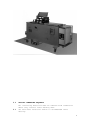
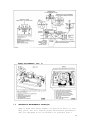
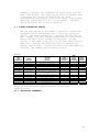
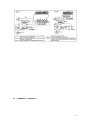
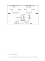
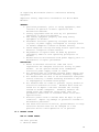
MICRO WELD
MODEL AD 3-5
HEAVY DUTY
NON-FERROUS
BUTT WELDERS
MICRO PRODUCTS COMPANY
SERVICE MANUAL
1
TABLE OF CONTENTS
1.0
2.0
3.0
4.0
5.0
6.0
7.0
8.0
9.0
10.0
11.0
12.0
13.0
1.0
SPECIFICATIONS
GENERAL OPERATING INSTRUCTIONS
BASIC OPERATING PARTS
BASIC OPERATING PARTS LOCATION
TYPICAL OPERATING SEQUENCE
SPECIAL ADJUSTMENTS
PREVENTIVE MAINTENACE
SUGGESTED SETTINGS
DIAGNOISTIC CHART FOR TROULBE-SHOOTING
ELECTRICAL SCHEMATIC
SAFETY REMINDERS
BUYERS GUIDE
PARTS LIST
SPECIFICATIONS
Welding Range Copper Wire
Welding Range Aluminum Wire
Welding Range Copper
Conductors
Welding Range Aluminum
Conductors
Maximum Line Demand 460 Volt
Maximum Line Demand 230 Volt
Single Phase AC Transformer
Clamp Method
Upset Method
Mounting
MODEL AD-3
.187 to .375 in. DIA.
.250 to .500 in. DIA.
.232 to .437 in. DIA.
4ga to 2/0
.292 to .547 in. DIA.
2ga to 250MCM
62amps@100% duty cycle
196amps@10% duty cycle
124amps@100% duty cycle
390amps@10% duty cycle
40 KVA @ 50% duty cycle
Pneumatic, Foot Controlled
Pneumatic, Adjustable
4-Caster Wheels/STD.
MODEL AD-4
.250 to .500 in. DIA.
.375 to .750 in. DIA.
.292 to .547 in. DIA.
2ga to 250MCM
.437 to .853 in. DIA.
2/0 to 550MCM
115 amps@100% duty cycle
362 amps@10% duty cycle
230 amps@100% duty cycle
724 amps@10% duty cycle
75 KVA @ 50% duty cycle
Pneumatic, Foot Controlled
Pneumatic, Adjustable
4-Caster Wheels/STD.
Dimensions and Weights
Height Overall
Floor Space
Welding Die Height
Weight
SPECIFICATIONS
Welding Range Copper Wire
Welding Range Aluminum Wire
Welding Range Copper
Conductors
Welding Range Aluminum
Conductors
Maximum Line Demand 460 Volt
Maximum Line Demand 575 Volt
Single Phase AC Transformer
Clamp Method
Upset Method
Mounting
50 in.
57 in. x 29 in.
43 in.
1350 LBS
50 in.
62 in. x 36 in.
43 in.
1500 LBS
MODEL AD-5
.375 to .750 in. DIA.
.500 to .875 in. DIA.
.437 to .853 in. DIA.
2/0 to 550MCM
.547 to .998 in. DIA.
250MCM to 750MCM
228amps@100% duty cycle
727amps@10% duty cycle
184amps@100% duty cycle
582amps@10% duty cycle
150 KVA @ 50% duty cycle
Pneumatic, Foot Controlled
Pneumatic, Adjustable
4-Caster Wheels/STD.
Dimensions and Weights
Height Overall
Floor Space
Welding Die Height
Weight
50 in.
62 in. x 36 in.
43 in.
1700 LBS
FEATURES
•
•
Micro Weld quality and workmanship
Heavy-duty construction & components
2
•
•
•
•
•
•
Easy to operate controls
Low maintenance costs
Easy to set welding parameters
Safety electrical switch circuits
Heavy-duty weld heat selection switch
Sensitive straight slide movable headpiece assembly
2.0
GENERAL OPERATING INSTRUCTIONS
2.1
ELECTRICAL HOOK-UP INSTRUCTIONS
First determine that available electrical service in your
plant corresponds to the nameplate rating located on welder
housing. Electrical wiring to welder must be of sufficient
size to deliver full ampere load with no appreciable loss
during weld cycle. The welder will not operate properly if
there is more than a 10% variation in the line voltage. In
general, the welder should be fused with a slow blow fuse
of the 100% duty cycle rating. The minimum power cable size
to the welder can be obtained by using this same current
rating.
Refer to National Electrical Code and local electrical
regulations for adequate power sizes; disconnect methods
and fusing guidelines.
Remember, line voltages to the welding machine are
potentially dangerous should the power cords be damaged or
severed. The welding voltages at the welding dies will not
harm an operator since they do not exceed 10 volts.
2.2
SAFETY PRECAUTIONS
(See section 11.0)
2.2.1 ELECTRICAL
Maintain electrical cable to welder in good repair. Welder
must be grounded and connections securely tightened. Heat
Switch must not be changed to new position while a weld
cycle is in process. Disconnect electrical service before
serving welder – high voltages are located within the base
of the welder.
2.2.2 MECHANICAL
Operator while using welder must wear safety glasses. Keep
all safety guards on welders and use properly. Operators
must be instructed on basic operation of unit to prevent
injury. Check nameplate rating and keep within material
size range for each welder.
3
2.3
WATER HOOK-UP
(If so equipped)
It is important that if a welder is to be operated for an
extended period of time and head heat up, water lines must
be connected to the welder. Connect hoses to inlet and
outlet provided at the back of the welder. Shut-off valve
should be installed in the inlet line and the hose from the
outlet should run to an open sight drain. Water should be
turned off when welder is not in use.
2.4
AIR HOOK-UP
Set air regulators for from 20 to 90 lbs. A safety pop-off
valve will be activated when air gauge is set for over 100
lbs.
2.5
WELDING DIES
The dies and shoes supplied with the welder will handle
most size and material types within the range of the
welder. For new weld applications consult the factory for
special die and shoe sets.
3.0
BASIC OPERATING PARTS
3.1
MODEL AD-3, 4 or 5
3.1.1 WELD HEAT SELECTION SWITCH
Welding heat is selected by means of a heavy-duty tap
switch with either eight or twelve steps of voltage. Number
one indicates the highest heat setting and number eight or
4
twelve indicates the lowest heat setting. The switch is
conveniently located on the lower front of the welder.
Note: The following items can be located on Print #B5800 in
Section 9.1.
3.1.2 HEADPIECE CLOSED SPACE ADJUSTING BOLT
The closed space-adjusting bolt is located on the movable
headpiece end plate. Refer to Item 1A.
3.1.3 HEADPIECE OPEN SPACE ADJUSTING BOLT
The open space-adjusting bolt is located on the upset
mechanism on the lever bar. Refer to Item E.
3.1.4 LIMIT SWITCH ADJUSTING BOLT
The limit switch-adjusting bolt is located on the lever bar
on the upset mechanism. Refer to Item F.
3.1.5 TOGGLE LINK
The toggle link is located on the upset mechanism. Refer to
Item G.
3.1.6 UPSET LEVER LIMITING BRIDGE
The upset lever limiting bridge is located on the upset
mechanism. Refer to Item H.
3.1.7 UPSET LEVER ARM
The upset lever arm is located in the middle of the upset
mechanism. Refer to Item I.
4.0
BASIC OPERATING PARTS LOCATION
5
5.0
5.1
TYPICAL OPERATING SEQUENCE
All insulating materials must be removed from conductors
where they contact lower welding dies.
Set weld heat selection switch to recommended chart
setting.
6
5.2
5.3
5.4
Set upset pressure to recommended chart setting (PSI).
Adjust the head open space to proper chart setting.
Place the stock into welding dies so wire ends meet midway
between each die. Clamp into position with foot valve
pedals.
5.5
Lower the flash guard and lift the operating lever until it
initiates the operation switch, hold for 1 to 3 seconds to
assure a complete weld cycle.
Unclamp welded conductors.
Trim off weld burr so welded area is equal to parent
material diameter. Incomplete burr removal or undercutting
of the weld area will result in subsequent weld breaks.
5.6
5.7
6.0
SPECIAL ADJUSTMENTS (FIG. 2)
6.1
Item “A” is used for head closed space adjustment. This
may have to be adjusted as die and shoe inserts wear, for
this reason it’s best to keep like size grooves in one die
set. As the ends wear they can be used until an even
amount takes place then adjust closed headspace again.
When replacing worn dies with new or rebuilt ones, turn
bolt “A” in about ½” or 12.7mm to prevent ends from being
damaged when adjusting new closed space.
To adjust new head closed space after new weld dies and
clamp shoes have been installed. Lift up on hand operated
air valve lever and hold in place with small wire through
ears on valve body and hole in lever. Adjust bolt “A”
until there is .005 to .010” to .127 to .254mm between
inserts in ends of weld dies. Lock bolt “A” in place with
locknut.
6.2
Item “E” head open space adjustments. This also adjusts
the amount of low-pressure travel on the weld cycle.
6.3
Item “F” limit switch adjustment screw. This screw should
be adjusted to where plunger on limit switch is pushed down
into threaded tube ¼”. This adjustment is made with nothing
in welding dies and initiating the operating lever.
6.4
Item “G” toggle link. This changes the vertical motion of
the upset lever to a horizontal movement.
7
6.5
Item “I” upset lever. This lever pivots at the rear with
air cylinder pushing front end of lever up. Angle ground on
front end of upset lever pushes against lazy arm roller
moving welder headpieces together.
6.6
Item “H” upset lever-restricting bridge, which limits
movement of upset lever.
6.7
AD-3, AD-4, & AD-5
ADJUSTMENTS AND DIE INSTALLATION
6.7.1 To prevent damage to dies or personal injury, disconnect
power and reduce air pressure gauges to “O”.
6.7.2 Loosen locknut on “closed” headpiece space adjusting screw
and turn screw in approximately 3/8” to allow clearance
between worn welding dies. Figure 1 and Designation “X”.
6.7.3 Loosen locknut on “open” headpiece space adjusting screw
and turn bolt counter clockwise to lower leverage bar.
Figure 1 and Designation “Y”.
6.7.4 Remove welding dies and clamp shoes.
6.7.5 Brighten with #2/0 emery cloth wipe clean:
A. Attaching surfaces of replacement welding dies – place
on flat surface to brighten.
B. Attaching surfaces of replacement welding die shoes –
place on flat surface to brighten.
C. Welding die seats on stationary and movable headpieces –
file with care to eliminate pitted or burnt surfaces.
Polish with emery cloth. (Note: Damaged die seats
indicate poor installation procedures or loose welding
dies).
D. Clamp arm die shoe seats – polish with emery cloth.
E. Wipe all contact surfaces with quick evaporating, low
residue cleaner.
6.7.6 Install new welding dies (lower set), welding die shoes
(upper set) and align.
A. Place clean welding dies in die seats and lightly
tighten into position. (Note: Die sets are marked with a
machining code).
B. Attach clean welding die shoes to clamp arms and lightly
tighten into position.
C. Select a straight piece of rod that corresponds to one
of the exact die grooves and place across and spanning
welding dies to assist in alignment.
8
D. Adjust upset air regulator to approximately 10 PSI and
clamp aligning rod into place.
E. Tap welding dies and die shoes into best alignment and
tighten upper die shoes.
F. Release clamp arms and carefully tighten welding dies.
6.7.7 Adjust upset air regulator to approximately 10 PSI and
activate operating lever, place the locking pin in topside
of air operating lever to hold movable headpiece in this
position. Adjust head “closed” adjusting screw to
specifications shown in Figures 1 and 1A. Tighten locknut.
6.7.8 With adjustment #7 completed, leave headpiece in adjusted
closed position and make following limit switch
adjustments.
A. Mark stem of depressed limit switch with pencil as shown
in Figure 1C.
B. Release operating lever to allow movable headpiece to
return to a rest position.
C. Check pencil mark to specifications shown in Figures 1
and 1C. Adjust limit switch adjusting screw to obtain
proper switch setting. Recheck if necessary. (Note:
Important adjustment as it determines fusion point of a
successful weld. Adjustment remains same for all sizes).
6.7.9 Headpiece open space may be checked by allowing movable
head to return to rest position. Adjust head “open”
adjusting screw to specifications in 1B.
6.7.10Restore correct air pressures and power to welder.
6.7.11Should the need arise to reset only the upset mechanism
adjustments steps 4, 5 and 6 may be eliminated.
WELDER ADJUSTMENTS AND LUBRICATION (FIG. 1)
9
UPSET ADJUSTMENTS (FIG. 2)
7.0
PREVENTIVE MAINTENANCE TECHNIQUE
Keep in Mind that these welders are precision built to last
many years, but will require proper maintenance procedures.
They are designed to be as automatic as possible with a
10
minimum dependence on the ability of the operator.
must make adjustments thoroughly familiar with the
operating principles of the welders.
Those
7.1 WELDING DIE NOTES
7.1.1 Welding dies and die shoes in poor condition are the
primary cause of poor quality welds.
7.1.2 Check die sets for excessive wear and replace if necessary.
7.1.3 Clean weld die bottoms to remove oxides with emery cloth
placed on a flat surface.
7.1.4 Clean die seats with emery cloth to brighten contact areas.
7.1.5 After cleaning of dies be sure to wipe off with soft clean
cloth.
7.1.6 Completely tighten dies into seats to assure a good
contact.
7.1.7 Worn dies will not hold stock during a weld cycle, replace
worn dies.
7.2 WEEKLY
7.2.1 Tighten all loose parts.
7.2.2 Check for water leaks (if applicable).
7.2.3 Check for air leaks.
7.2.4 Drain airline filter bowls.
7.2.5 Tighten all loose parts.
7.3 QUARTERLY
7.3.1 Repeat above service items.
7.3.2 Check grease requirements on clamp arms pivot shafts and
lubrication points.
7.3.3 Check anneal parts and replace all worn or broken
assemblies
7.3.4 Check contacts on magnetic contactor for worn contacts.
7.3.5 Clean heat switch contacts with low residue cleaner and
recoat with petroleum jelly.
7.4 ANNUALLY
7.4.1 Repeat previously noted items.
7.4.2 Check for wear in clap arm pivots.
7.4.3 Clean inside and outside of welder.
7.4.4 Check grease requirements on headpiece slide shafts, grease
lightly.
7.4.5 Caution: make sure that power supply is disconnected before
servicing welder in anyway!
7.5
WELDING DIES AND DIE SHOES INFORMATION
Description:
Welding dies – Lower conducting electrode and clamp jaw.
Welding die shoes – Upper clamping member.
Welding dies and die shoes in poor condition are the main
causes of bad welds.
Care of die sets:
11
7.5.1 Use a brass or fiber blade to remove particles of flashings
that build-up on die sets. Excessive flash build-up causes
die burns on material and shorting of die sets.
7.5.2 Do not attempt to clamp material that is not suited for
welder into die sets. Undersize materials will slip and
burn die grooves, oversize materials will overstress
clamping parts.
7.5.3 Do not use welding die sets for a vise.
not withstand the mechanical abuse.
These parts will
7.5.4 Whenever welding dies are replaced, clean bottoms of dies
and corresponding die seats to a bright and clean condition
before bolting them tightly into place. An oxidized
surface will insulate the welding dies and reduce effective
welding voltage.
7.5.5 Welding die set will wear with use and must be changed
occasionally for good welding results. Keep and adequate
supply of replacement parts available. Wire and rod
slippage is a problem caused by poor die sets and a major
cause of wire breaks.
8.0 SUGGESTED SETTINGS
Material
Model AD-3
Aluminum Rod
Aluminum Rod
Copper Rod
Copper Rod
Copper
Aluminum
Size
Weld
Heat
Setting
Die
Closed
Space
Die
Open
Space
.375
.250
.250
.375
4 GA.
250MCM
7
11
5
2
6
1
.005
.005
.005
.005
.005
.005
.375
.250
.250
.375
.500
.625
Upset
Pressure
25
20
30
30
30
40
PSI
PSI
PSI
PSI
PSI
PSI
Clamp
Pressure
90
90
90
90
90
90
PSI
PSI
PSI
PSI
PSI
PSI
Limit
Switch
Setting
Upset
Arm
Movement
¼
¼
¼
¼
¼
¼
12
Model AD-4
Aluminum Rod
Aluminum Rod
Copper Rod
Copper Rod
Copper
Aluminum
Aluminum
Model AD-5
Aluminum Rod
Aluminum Rod
Copper Rod
Copper Rod
Aluminum
Aluminum
Copper
Copper
.375
.750
.375
.500
350MCM
#2
350MCM
4
2
4
1
2
11
5
.005
.005
.005
.005
.005
.005
.005
.375
.750
.375
.500
.500
.625
.625
30
40
35
45
40
35
55
PSI
PSI
PSI
PSI
PSI
PSI
PSI
90
90
90
90
90
90
90
PSI
PSI
PSI
PSI
PSI
PSI
PSI
¼
¼
¼
¼
¼
¼
¼
.375
.750
.375
.750
#2
500MCM
500MCM
#2
6
1
4
1
8
4
1
5
.005
.005
.005
.005
.005
.005
.005
.005
.375
.750
.375
.750
.500
.625
.625
.500
30
35
25
45
30
35
35
30
PSI
PSI
PSI
PSI
PSI
PSI
PSI
PSI
90
90
90
90
90
90
90
90
PSI
PSI
PSI
PSI
PSI
PSI
PSI
PSI
¼
¼
¼
¼
¼
¼
¼
¼
8.1 WELD EXAMPLES
9.0 DIAGNOSTIC CHART FOR TROUBLE SHOOTING
Welding Action
Welding action normal burr
does not extend beyond rod
Molten metal blown out and
material does not join
Weld area does not heat
enough to complete weld
Dry looking weld
Cause
Shear cut
Remedy
Increase stating space
High heat
Limit switch adjust
Small stock
Low upset pressure
Air system
Low heat
Transformer secondary
connection
Welding dies
Staring space
Upset pressure
Lower heat setting
Set to depress ¼”
Check nameplate rating
Increase upset pressure
Clean air filters
Increase heat settings
Clean and tighten
Clean and tighten
Decrease starting space
Decrease settings
13
Misalignment of rod
Rod ends buckle and not
welded
Welder inoperative
Variations in welds
Limit switch
Worn die grooves
Starting space
Welder head loose
Weld heat
Starting space
Upset pressure
Welding dies
Fuses
Time delay switch
Operating or limit switch
Heat switch
Contactor
Welding transformer
Auto-transformer
Stock slippage
Input voltage
Loose transformer secondary
Loose welding dies
Binding movable headpiece
rod connection
Preparing rod end
Weld contactor
Time delay switch in weld
circuit
9.1
Set to depress ¼”
Replace die sets
Decrease staring space
Return for reconditioning
Increase heat
Decrease starting space
Decrease pressure
Clean or replacement
Check power supply
Check continuity of circuits
Check continuity of circuits
Tighten loose connections
Check continuity of circuits
Check continuity of circuits
Check continuity of circuits
Undersize stock
Replace worn dies
Set clamp pressure to 90 psi
Leaking clamp cylinder
Check power input
Only 5% drop permissible
Inadequate wiring
Clean and tighten
Clean and tight or replace
Remove all rod ends
Clean contact area
Replace rod cutter jaws
Require consistent cuts
Replace contacts and check
operation
Increase air stabilization
time-install timer on early
units
ELECTRICAL TROUBLE-SHOOTING OF WELDER
(Caution! Extreme care should be exercised when making
these tests. Dangerous voltages are present in the welder.
Only persons familiar with electrical safety precautions
should perform these tests.)
9.1.1 TROUBLE-SHOOTING TABLE
(See section 9.1.3)
This electrical trouble-shooting table is furnished as a
suggested method of trouble-shooting the welder. The
individual steps of the table should be performed in the
order given, to make the tests valid. The electrical
14
schematic (section 10) furnished for these tests show the
table test points. The table may be used for welders with
a different but closely related wiring by using
corresponding test points. During all tests, line voltage
should be connected to L1 & L2 of the welder. The heat
switch should be set to the #1 position.
9.1.2 FINAL ELECTRICAL CHECKS
Set the heat switch to the number 1 position; connect the
voltmeter across the welding dies. Press the operating
switch. The meter reading will typically be less than 10
VAC. Consult the weld specification sheet for this value.
Rotate the heat switch through all settings. If the
voltage is not read at any setting, the heat switch may be
defective. Actuate the weld limit switch; observe the
reading goes to zero. Release the weld limit and operating
switches, the reading should remain at zero.
9.1.3
TEST
LEAD
CONNECTION
X1 X2
X2 FU1-1
X2 FU1-2
X2 PB1-1
X2 PB1-2
X2 LS1-2
X2 LS2-1
X2
X2
X2
X2
L2
L2
LS2-2
PB2-1
PB2-2
TR1-3
CR1-1
CR1-2
METER
READING
115 VAC
115 VAC
115 VAC
115 VAC
115 VAC
115 VAC
115 VAC
115 VAC
115 VAC
115 VAC
115 VAC
Line voltage
Line voltage
PROBLEM
IF NO
READING
Bad control transformer
Bad fuse connection
Open fuse
Open wire to operating switch
Bad operating switch
Open flashguard switch
Open wire to weld limit
switch
Open weld limit switch
Open wire to anneal switch
Bad anneal switch
Bad time delay relay
Open wiring to contactor
Bad contactor
PRESS
OPERATING
SWITCH
WELD
LIMIT
SWITCH
ACTUATED
PRESS
ANNEAL
SWITCH
X
X
X
X
X
X
X
NOTE: To perform repair consult section 13 for parts
identification.
10.0 ELECTRICAL SCHEMATIC
15
10.1 PNEUMATIC SCHEMATIC
16
11.0 SAFETY REMINDERS
The following accident prevention information is presented
to eliminate potential hazards while operating, inspecting
17
or repairing Micro-Weld electric resistance welding
equipment.
Important safety compliance information for Micro-Weld
Welders.
GENERAL
1. Qualified personnel, prior to using equipment, must
instruct an operator on basic operation and
malfunction methods.
2. Safety eyeglasses must be worn by all personnel
operating or servicing welders.
3. Use safety equipment properly and keep safety
equipment on welders.
4. Determine that both operating voltages and hertz
(cycles) of power supply correspond to ratings listed
on welder nameplate located on welder housing.
5. Check nameplate ratings and keep within capacities and
material categories stated therein.
6. Adjustments or repairs must be made by persons
thoroughly familiar with operating principles of
welder.
7. Welder must be disconnected from power supply prior to
maintenance or repair procedures.
ELECTRICAL
1. Refer to National Electrical Code and local
regulations for adequate electrical wiring to power
welder. Do not operate welder with inadequate
electrical power supply cords or cable.
2. All welders must be grounded through power supply and
welder ground connection terminal securely tightened.
3. All welders must be able to be disconnected from power
source either by a double breaking disconnect switch
or unplugged by standard rated plugs.
4. All welders must be fused to prevent injury should an
electrical malfunction occur. Welders must never be
fused for an ampere load that exceeds the ratings
stated on welder nameplate. Normally welders are
fused using the nameplate rated load; time lag
parameters functional to standard fuses allow this
specification.
5. Electric power cords to welder must be kept in good
condition. Report any damage or potential hazards to
maintenance personnel.
6. The weld heat selection switch, potentiometer or range
selection devices must not be changed to a new
position while a weld operation is in process.
12.0 BUYERS GUIDE
HOW TO ORDER PARTS:
You must provide
1. Machine Model
18
2. Machine Serial Number
3. Voltage
Then identify part(s) on part list (last page in book) and
provide MICRO with the circled number.
CALL MICRO at 800-872-1068
OR FAX MICRO at 630-787-9360
Provide MICRO with your company name and purchase order
number.
13.0 PARTS LIST
19
20
21
22
23
PARTS LIST AD3, AD4, AD5
MODEL/
DESCRIPTION
PART NO
D-01A
Basic head assembly
D-01B
Complete head assembly
D-04
Shaft wipes
D-04A
Shaft wipe retaining ring
D-05
Head return spring
D-08L
Clamp arm, left
D-08R
Clamp arm, right
D-09
Arm pivot pin bronze
D-10
Arm pin washer
D-10A
Arm pin bolt
D-11
Grease zerk, 90 degrees
D-12
Clamp cylinder #50
D-12A
Cylinder replacement diaphragm #50
D-12B
Cylinder shaft boot #50
D-12C
Clamp cylinder clevis #50
D-13
Foot pedal
D-13A
Hand valve (special Suspended weld)
D-14
Pedal mount screw
D-20
End plate, stationary head (AD4, AD5)
D-20
End plate, stationary head (AD3)
D-21
End plate mount bolt, stationary head (AD3-AD5)
D-21
End plate mount bolt, stationary head (AD4)
D-22
End plate movable head
D-23
End plate mount bolt, movable head
D-24
Push up block
D-25
Closed space bolt, adjustable
D-25A
Closed space locknut
D-26
Push up block insulating plate
D-11A
Grease zerk, straight
D-26A
Insulating tube
D-26B
Insulating washer
D-27
Push up block mount bolt
D-30
Stationary anneal extension bar (AD3)
D-30
Stationary anneal extension bar (AD4-AD5)
D-31
Front anneal bar
D-32
Anneal bar mount bolts
D-33
Movable anneal extension bar
D-34A
Anneal bar bracket (AD5)
D-35
CA anneal, each (front)
D-36
CAL anneal, pair
D-37
Anneal clamp mount bolt
D-40
Complete truck (AD3)
D-40
Complete truck (AD4)
D-40
Complete truck (AD5)
D-41
Truck door
D-43
Swivel caster
ITEM #
30654
30655
30640
48219
80059
30554
30614
30502
30517
90258
48422
77706
77713
77718
77727
77859
77864
90611
30548
50502
90664
90687
30518
90203
30503
30506
92107
30504
48423
30638
92906
90260
62078
62079
62080
90260
62081
62082
62155
62020
90260
40599
40592
40600
40540
48108
24
PARTS LIST AD3, AD4, AD5
MODEL/
PART NO
D-44
D-45
D-46
D-47
D-47H
D-48
D-48H
D-49
D-50
D-51
D-51A
D-51B
D-51C
D-51D
D-52
D-53
D-54
D-55
D-56
D-56
D-56
D-57
D-64A
D-64
D-65
D-70A
D-70B
D-70C
D-70AP
D-70BP
D-70CP
D-70AS
D-70BS
D-70CS
D-71
D-71
D-71
D-71A
D-72
D-73
D-75
D-75C
D-75P
D-78
DESCRIPTION
ITEM #
Stationary caster (special order)
#4 shear, long handle
Shear mount bolt
Standard vise
Heavy duty vise
Standard vise bracket
Heavy duty vise bracket
Vise bracket mount bolt
Vise mount bolt
Flashguard assembly less switch
Flash shield
Flash shield bracket assembly
Pivot plate assembly
Pivot screw
Flashguard mount bolt
Flashguard safety switch
Upset cover
Upset cover mount screw
Flash tray (AD3)
Flash tray (AD4)
Flash tray (AD5)
Flash tray mount bolt
Shoe attaching washer
Shoe mount bolt
Die mount bolt
Transformer, weld, state voltage & serial
number(AD3)
Transformer, weld, state voltage & serial
Number (AD4)
Transformer, weld, state voltage & serial
Number (AD5)
Primary coil, state voltage & serial number(AD3)
Primary coil, state voltage & serial number(AD4)
Primary coil, state voltage & serial number(AD5)
Secondary (AD3)
Secondary (AD4)
Secondary (AD5)
Transformer ring (AD3)
Transformer ring (AD4)
Transformer ring (AD5)
Lower transformer ring (AD4-AD5)
Transformer studs ½” NC
Transformer studs ¾”-NC
Auto transformer (AD3-AD4)
Auto transformer ring (AD3-AD4)
Primary (AD3-AD4)
Control circuit step-down transformer
48117
64009
90295
78112
78111
60022
60005
90295
90262
30656
30500
30519
30639
93078
30672
57813
30516
90656
40502
40500
40501
90258
92754
90677
90657
50551
50546
50547
53049
50545
50541
50550
50512
50528
50504
50506
50505
50536
50518
50521
50567
42593
50568
57602
25
PARTS LIST AD3, AD4, AD5
MODEL/
PART NO
D-79
D-80
D-82
D-83A
D-83C
D-85
D-87
D-90
D-91
D-92
D-93
D-94
D-95
D-96
D-96A
D-97
D-99
D-100
D-101
D-101A
D-101B
D-102
D-104
D-105
D-106
D-106A
D-106B
D-106C
D-107
D-107A
D-107B
D-107C
D-159
D-210
D-211
AD-59T2
AD-59T2
AD59T2C
AD-59T3
AD-59T1
DESCRIPTION
ITEM #
8pt heat switch (AD5)
12 point heat switch (AD3)
Heat switch mount bolt
Contactor
Contactor repair kit
Pneumatic time delay switch
Terminal block
Upset frame
Upset frame mount bolt
Lever bar
Lever bar pivot pin
Pivot pin, bearing & upset pin
Pivot pin retaining screw
Limit switch adjust screw
Limit switch screw locknut
Limit switch
Open space adjust bolt
Toggle link
Upset pin
Reduced diameter upset pin
Reduced diameter pin end cap
Upset pin retaining washer & bolt
Toggle link pivot pin
Toggle pivot pin retaining screw
Upset cylinder #30 (AD3-AD4)
Replacement diaphragm #30 (AD3-AD4)
Cylinder shaft boot #30 (AD3-AD4)
Upset cylinder clevis #30 (AD3-AD4)
Upset cylinder #36 (AD5)
Replacement diaphragm #36 (AD5)
Cylinder shaft boot #36 (AD5)
Upset cylinder clevis #36 (AD5)
Clamp cylinder flow control valve
Air regulator station complete (see separate
part list)
Muffler
56548
56547
90294
57611
Dies
Standard radius groove dies, stellite inserts,
conical tips, state size (0 - .500)
Standard radius groove dies, stellite inserts,
conical tips, state size (.500 - .750)
Standard radius groove dies, stellite inserts,
custom tips, state sizes
Standard radius groove dies, stellite inserts 3
grooves, state sizes
Broach radius groove dies, stellite inserts,
state size
Application
57661
53000
30515
90294
30513
30508
48403
90015
53005
92056
59084
30510
40554
30511
92557
30507
30637
30512
90015
77704
77711
77717
77727
77705
77712
77717
77727
77862
59511
77892
30595
30596
30597
30598
30624
26
27