1
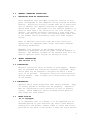
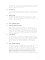
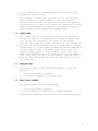
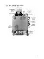
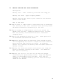
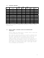
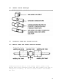
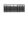
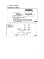
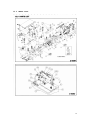
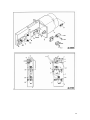
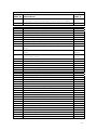
MICRO WELD
MODEL HP-1
CERAMIC FUSION
BUTT WELDERS
MICRO PRODUCTS COMPANY
SERVICE MANUAL
1
TABLE OF CONTENTS
1.0
2.0
3.0
4.0
5.0
6.0
7.0
8.0
9.0
10.0
11.0
12.0
13.0
1.0
SPECIFICATIONS
GENERAL OPERATING INSTRUCTIONS
BASIC OPERATING PARTS
BASIC OPERATING PARTS LOCATION
TYPICAL OPERATING SEQUENCE
SPECIAL ADJUSTMENTS
PREVENTIVE MAINTENACE
SUGGESTED SETTINGS
DIAGNOISTIC CHART FOR TROULBE-SHOOTING
ELECTRICAL SCHEMATIC
SAFETY REMINDERS
BUYERS GUIDE
PARTS LIST
SPECIFICATIONS
MODEL HP1
Type of Welding Process
Welding Range
Material Suitability
Standard Operating Voltages
Maximum Line Demand 460 Volt
Maximum Line Demand 230 Volt
Single Phase AC Transformer
Clamp Method
Upset Method
Mounting
Ceramic Fusion
4/0 to 8ga AWG-Copper
250MCM to 8GA Aluminum
Strand or Bunched Conductor
460/230 Volts
37amps@100% duty cycle
117amps@10% duty cycle
74amps@100% duty cycle
234amps@10% duty cycle
24 KVA @ 50% duty cycle
Pneumatic, Foot Controlled
Pneumatic, Adjustable
4-Caster Wheels
Dimensions and Weights
Height Overall
Floor or Bench space
Welding Die Height
Weight
46”-Truck
39” x 29” Truck Type
41” – Truck Type
640 LBS – Truck Type
FEATURES OF MICRO-WELD CERAMIC FUSION WELDING EQUIPMENT
•
•
•
•
•
•
•
•
•
Micro Weld quality and workmanship
Heavy-duty construction & components
East to operate controls
Low maintenance costs
Easy to set welding parameters
Safety electrical switch circuits
Heavy-duty weld heat selection switch
No-upset burr formation during weld process, all strands
locked into weld coalescence
Sensitive straight slide movable headpiece assembly
equipped with ball bearings
2
2.0
GENERAL OPERATING INSTRUCIONS
2.1
ELECTRICAL HOOK-UP INSTRUCTIONS
First determine that available electrical service in your
plant corresponds to the nameplate rating located on welder
housing. Electrical wiring to welder must be of sufficient
size to deliver full ampere load with no appreciable loss
during weld cycle. The welder will not operate properly if
there is more than a 10% variation in the line voltage. In
general, the welder should be fused with a slow blow fuse
of the 100% duty cycle rating. The minimum power cable size
to the welder can be obtained by using this same current
rating.
Refer to National Electrical Code and local electrical
regulations for adequate power sizes; disconnect methods
and fusing guidelines.
Remember line voltages to the welding machine are
potentially dangerous should the power cords be damaged or
severed. The welding voltages at the welding dies will not
harm an operator since they do not exceed 10 volts.
2.2
SAFETY PRECAUTIONS
(See section 11.0)
2.2.1 ELECTRICAL
Maintain electrical cable to welder in good repair. Welder
must be grounded and connections securely tightened. Heat
Switch must not be changed to new position while a weld
cycle is in process. Disconnect electrical service before
serving welder – high voltages are located within the base
of the welder.
2.2.2 MECHANICAL
Operator while using welder must wear safety glasses. Keep
all safety guards on welders and use properly. Operators
must be instructed on basic operation of unit to prevent
injury. Check nameplate rating and keep within material
size range for each welder.
2.3
WATER HOOK-UP
(If so equipped)
It is important that if a welder is to be operated for an
extended period of time and heats up, water lines must be
connected to the welder. Connect hoses to inlet and outlet
provided at the back of the welder. A Shut-off valve should
3
be installed in the inlet line and the hose from the outlet
should run to an open sight drain. Water should be turned
off when welder is not in use.
2.4
AIR HOOK-UP
Set air regulators for from 20 to 80 lbs. A safety pop-off
valve will be activated when air gauge is set for over 100
lbs.
2.5
WELDING DIES
The dies and shoes supplied with the welder will handle
most size and material types within the range of the
welder. For new weld applications consult the factory for
special die and shoe sets.
3.0
BASIC OPERATING PARTS
3.1
WELD HEAT SELECTION SWITCH
Welding heat is selected by means of a heavy-duty tap
switch, offering twelve (12) steps of voltage. The switch
is located conveniently on the lower front of the welder.
Number one (1) indicates high heat; twelve (12) indicates
low welding heat. Other numbers are equally graduated from
high to low to allow just the right amount of voltage for
the weld operation.
3.2
LIMIT SWITCH
The weld switch is located on the upset cylinder bracket
behind the upset cylinder. Limit switch adjustment is made
by moving the switch-initiating barrel along the threaded
stud mounted in the movable headpiece. The weld limit
switch controls the cut of current flow to the welding
dies.
3.3
HEAD SPACING MECHANISM
The open head space adjustment bolt and locking jam nut are
located on the upset cylinder mounting plate to the
immediate left front of the upset cylinder, The open space
scale also located on the front of the upset cylinder
mounting is a quick reference guide for determining the
amount of open space by lining up the pointer on the
movable head endplate with the graduations on the scale.
When the pointer is in line with no. “0” on the scale,
there is 3/8” between the inside of the welding dies. There
4
is an increase of ¼” spacing between the dies for each
graduation on the scale.
The headpiece closed stop is preset at the factory and
should require no field attention. This setting will
prevent the dies from touching each other if the upset is
activated with no stock in the dies. To check this setting
push movable headpiece to the full closed space then you
should measure 3/8” between the welding dies.
3.4
CLAMP ARMS
The clamp arms are air operated. The foot controlled air
valves are used to initiate the air clamp cylinders. The
foot valves are located at the bottom of the welder
housing. The right foot pedal operates the right clamp arm,
and the left pedal operates the left clamp arm. To clamp
stock place it in the proper welding die grooves and press
the top edges of the tilt pedal on the foot valve. To
release stock, press on bottom edge of foot valve tilt
pedal. Air flowing into each clamp cylinder is slowed by a
flow valve that is preset at the factory. CAUTIOM: Care
must be used when clamping stock, be sure hands are clear
of clamp arms.
3.5
WELDING DIES
The welding dies (lower) and shoes (upper), serve two
purposes:
1. To carry current for welding.
2. To prevent slippage during weld cycle.
3.6
WELD SPLIT SLEEVE
The split sleeve serves two purposes:
1. To provide proper alignment.
2. To form weld zone keeping all strands together.
With the unique design each sleeve can be used many times.
5
4.0
BASIC OPERATING PARTS LOCATION
6
5.0
TYPICAL OPERATING SEQUENCE
5.1
All insulating materials must be removed from conductors
where they contact lower welding dies.
Set weld heat selection switch to recommended chart
setting.
Set upset pressure to recommended chart setting (PSI).
Adjust the head open space to proper chart setting.
Twist end of conductor in direction of natural lay, pulling
outward.
Carefully square cut conductor end so no individual wires
extend beyond cut. Note: Use a sharp sheer, because end
preparations are important.
Select correct ceramic sleeve or split sleeve set for wire
to be welded.
Thread conductor into sleeve so that the wire ends are
midway through sleeve. Rotating sleeve in direction of lay
will assist threading procedures.
Clamp preset conductor and sleeve into welding die set, so
that the sleeve is centered between open welding dies.
Thread other prepared conductor into sleeve and allow the
conductor to gently but firmly contact first conductor.
Positive contact to wire ends is important for a good weld.
Clamp that conductor into welding die.
Rotate and center ceramic (or split) sleeve to assure free
movement of conductors during the weld process.
Lower the flash guard and raise up on the operating lever
until it initiates the operation switch, hold for 1 to 3
seconds to assure a complete weld cycle.
Unclamp welded conductors and remove sleeve. Fracture
expendable type or disassemble reusable type.
The inside diameter of the sleeve slightly exceeds the
nominal conductor size; therefore the weld zone is slightly
larger than conductor diameter.
5.2
5.3
5.4
5.5
5.6
5.7
5.8
5.9
5.10
5.11
5.12
5.13
5.14
7
6.0
SPECIAL ADJUSTMENTS
6.1
HEADPICE OPEN SPACE ADJUSTMENTS
The typical open space for the HP Welder should be set at
4-1/2 on the open space scale. If the open space need
adjusting, loosen the locknut on the open space bolt to
increase the open space turn clockwise, to decrease the
open space turn the bolt counterclockwise after adjusting
retighten locknut. (See suggested settings).
6.2
LIMIT SWITCH
The weld limit switch adjustment is typically set at 4-1/2
on the threaded rod scale. If the weld limit needs
adjusting loosen the locknut on the threaded rod, turn
activating nut clockwise to cut off sooner or turn the nut
counterclockwise to cut off later. (See suggested
settings).
6.3
UPSET PRESSURE
A pressure regulator with gauge controls the upset
pressure. To change the upset pressure loosen the locknut
on the adjusting knob screw, to increase pressure turn knob
clockwise, to decrease pressure turn knob counterclockwise,
retighten locknut after adjustment has been made.
6.4
CLAMP PRESSURE
A pressure regulator with gauge controls the clamp
pressure. To change the clamp pressure, loosen the locknut
on the adjusting knob screw, to increase pressure turn knob
clockwise to decrease pressure turn knob counterclockwise,
retighten locknut after adjustment has been made.
8
7.0
PREVENTIVE MAINTENANCE TECHNIQUE
Keep in Mind that these welders are precision built to last
many years, but will require good maintenance procedures.
They are designed to be as automatic as possible with a
minimum dependence on the ability of the operator.
Adjustments must be made by those thoroughly familiar with
the operating principles of the welders.
7.1 WELDING DIE NOTES
7.1.1 Welding dies and die shoes in poor condition are the
primary caused of bad welds.
7.1.2 Check die sets for excessive wear and replace if necessary.
7.1.3 Clean weld die bottoms to remove oxides with emery cloth
placed on a flat surface.
7.1.4 Clean die seats with emery cloth to brighten contact areas.
7.1.5 After cleaning of dies be sure to wipe off with soft clean
cloth.
7.1.6 Completely tighten dies into seats to assure a good
contact.
7.1.7 Worn die shoes will not hold stock during a weld cycle,
change steel faces or replace complete shoes.
7.2 WEEKLY
7.2.1 Tighten all loose parts.
7.3 QUARTERLY
7.3.1 Repeat above service items.
7.3.2 Check grease requirements on clamp arms pivot shafts and
lubrication points.
7.3.3 Check anneal parts and replace all worn or broken
assemblies
7.3.4 Check contacts on magnetic contactor for worn contacts.
7.3.5 Clean heat switch contacts with low residue cleaner and
recoat with petroleum jelly.
7.4 ANNUALLY
7.4.1 Repeat previously noted items.
7.4.2 Check for wear in clap arm pivots.
7.4.3 Clean inside and outside of welder.
7.4.4 Check grease requirements on headpiece slide shafts, grease
lightly.
7.4.5 Caution: make sure that power supply is disconnected before
servicing welder in anyway!
9
7.5
WELDING DIES AND DIE SHOES INFORMATION
Description:
Welding dies – Lower conducting electrode and clamp jaw.
Welding die shoes – Upper clamping member.
Welding dies and die shoes in poor condition are the main
causes of bad welds.
Care of die sets:
7.5.1 Use a brass or fiber blade to remove particles of flashings
that build-up on die sets. Excessive flash build-up causes
die burns on material and shorting of die sets.
7.5.2 Do no attempt to clamp material that is not suited for
welder into die sets. Undersize materials will slip and
burn die grooves, oversize materials will overstress
clamping parts.
7.5.3 Do not use welding die sets for a vise.
not withstand the mechanical abuse.
These parts will
7.5.4 Whenever welding dies are replaced, clean bottoms of dies
and corresponding die seats to a bright and clean condition
before bolting them tightly into place. An oxidized
surface will insulate the welding dies and reduce effective
welding voltage.
7.5.5 Welding die shoes must swivel freely within the clamp arm
pivots to prevent cracking of die shoes. File down die
shoe boss if necessary.
7.5.6 Welding die set will ear with use and must be changed
occasionally for good welding results. Keep and adequate
supply of replacement parts available. Wire and rod
slippage is a problem caused by poor die sets and a major
cause of wire breaks.
10
8.0
SIZE
8 GA
6 GA
4 GA
3 GA
2 GA
1 GA
1/0
2/0
3/0
4/0
8 GA
6 GA
4 GA
3 GA
2 GA
1 GA
1/0
2/0
3/0
4/0
SUGGESTED SETTINGS
MATERIAL
Copper
Copper
Copper
Copper
Copper
Copper
Copper
Copper
Copper
Copper
Aluminum
Aluminum
Aluminum
Aluminum
Aluminum
Aluminum
Aluminum
Aluminum
Aluminum
Aluminum
WELD
HEAT
SETTING
10
9
8
8
8
7
7
7
6
6
12
11
10
10
10 or 9
9
9
9
8
8 or 7
HEAD
OPEN
SPACE
4 ½
4 ½
4 ½
4 ½
4 ½
4 ½
4 ½
4 ½
4 ½
4 ½
4 ½
4 ½
4 ½
4 ½
4 ½
4 ½
4 ½
4 ½
4 ½
4 ½
LIMIT
SWITCH
SETTING
4 ½
4 ½
4 ½
4 ½
4 ½
4 ½
4 ½
4 ½
4 ½
4 ½
4 ½
4 ½
4 ½
4 ½
4 ½
4 ½
4 ½
4 ½
4 ½
4 ½
AIR
UPSET
20 PSI
20 PSI
20 PSI
25 PSI
25 PSI
25 PSI
30 PSI
40 PSI
45 PSI
50 PSI
15 PSI
15 PSI
15 PSI
20 PSI
20 PSI
25 PSI
25 PSI
30 PSI
35 PSI
40 PSI
AIR
CLAMP
60 PSI
60 PSI
60 PSI
60 PSI
60 PSI
60 PSI
60 PSI
60 PSI
60 PSI
60 PSI
60 PSI
60 PSI
60 PSI
60 PSI
60 PSI
60 PSI
60 PSI
60 PSI
60 PSI
60 PSI
NOTE: These settings are approximate and may be varied to obtain
the best weld.
8.1
WELDED STRAND OR BUNCHED COPPER AND ALUMINUM WIRE
CONDUCTORS
Theory: Welds are formed within a ceramic tube or block and
no filler materials are needed.
Wire ends are resistance heated to a plastic condition and
hot forged together within a ceramic tool, which acts as a
crucible. The resultant coalescence (weld) locks all
single filaments into a solid weld zone…Since strand
conductors have configuration voids on the faying surfaces,
the plastic material normally forced to the outside on a
normal weld, is forced into the voids eliminating the upset
burr common with standard upset weld. (This type of weld
is not suitable for solid wire.)
11
8.2
CERAMIC FUSION TECHNIQUE
9.0
DIAGNOSTIC CHART FOR TROUBLE-SHOOTING
9.0.1 SERVICE HINTS FOR STRAND CONDUCTOR WELDERS
Conductors must be able to slide freely within ceramic tools
during weld cycle, therefore rotate and move ceramic tool side to
side prior to welding. Be sure to center ceramic tool between
die sets.
12
Porosity and voids in weld zone may be corrected by using one or
more of the following suggestions.
1. Increase upset pressure.
2. Decrease weld heat
3. Readjust timing point of weld heat cut-off, limit switch
adjustment, to allow heat to cut-off slightly sooner.
4. Check to make sure conductor is not binding in ceramic
tool.
Amount and length of weld nugget (solid portion of weld) can be
varied by one or more of the following suggestions.
1. Increase starting space between die sets when weld nugget
is small.
2. Decrease space between die sets when weld nugget is too
large.
3. Adjusting limit switch to hold on or cut-off current at a
different position.
13
Fracturing of ceramic tools and bent conductors can be corrected
by one or more of the following methods.
1. Decrease weld heat to prevent excessive softening of
conductors on either side of sleeve.
2. Decrease starting space so as to decrease length of upset
and amount of conductor exposed to heat.
3. Decrease upset pressure and still maintain a fused area.
4. A few of the very small stranded and bunched conductors
just do not have enough mechanical strength to be processed
by this process.
9.1
ELECTRICAL TROUBLE-SHOOTING OF WELDER
(Caution!! Extreme care should be exercised when making
these tests. Dangerous voltages are present in the welder.
Only persons familiar with electrical safety precautions
should perform these tests.)
9.1.1 TROUBLE-SHOOTING TABLE
(See section 9.1.3)
This electrical trouble-shooting table is furnished as a
suggested method of trouble-shooting the welder. The
individual steps of the table should be performed in the
order given, to make the tests valid. The electrical
schematic (section 10) furnished for these tests show the
table test points. The table may be used for welders with
a different but closely related wiring by using
corresponding test points. During all tests, line voltage
should be connected to L1 & L2 of the welder. The heat
switch should be set to the #1 position.
9.1.2 FINAL ELECTRICAL CHECKS
Set the heat switch to the number 1 position, connect the
voltmeter across the welding dies. Press the operating
switch. The meter reading will typically be less than 10
VAC. Consult the weld specification sheet for this value.
Rotate the heat switch through all settings. If the
voltage is not read at any setting, the heat switch may be
defective. Actuate the weld limit switch; observe the
reading goes to zero. Release the weld limit and operating
switches, the reading should remain at zero.
14
9.1.3
TEST
LEAD
CONNECTION
X1 X2
X2 FU1-1
X2 FU1-2
X2 LS1-1
X2 LS1-2
X2 LS2-1
X2 LS2-2
X2 LS3-1
X2 LS3-2
L2 CR1-1
L2 CR1-2
L1 S1-1
METER
READING
115 VAC
115 VAC
115 VAC
115 VAC
115 VAC
115 VAC
115 VAC
115 VAC
115 VAC
Line voltage
Line voltage
Line voltage
PROBLEM
IF NO
READING
Bad control transformer (T1)
Bad fuse connection
Open fuse
Open wire to operating switch
Bad operating switch
Open wire to flashguard switch
Open flashguard switch
Open wire to weld limit switch
Bad weld limit switch
Open wiring to contactor
Bad contactor
Open wire to heat switch
PRESS
OPERATING
SWITCH
WELD
LIMIT
SWITCH
ACTUATED
PRESS
ANNEAL
SWITCH
X
X
X
X
X
X
X
NOTE: To perform repair consult section 13 for parts
identification.
15
10.0 ELECTRICAL SCHEMATIC
16
11.0 SAFETY REMINDERS
The following accident prevention information is presented
to eliminate potential hazards while operating, inspecting
or repairing Micro-Weld electric resistance welding
equipment.
Important safety compliance information for Micro-Weld
Welders.
GENERAL
1. Qualified personnel, prior to using equipment, must
instruct an operator on basic operation and
malfunction methods.
2. Safety eyeglasses must be worn by all personnel
operating or servicing welders.
3. Use safety equipment properly and keep safety
equipment on welders.
4. Determine that both operating voltages and hertz
(cycles) of power supply correspond to ratings listed
on welder nameplate located on welder housing.
5. Check nameplate ratings and keep within capacities and
material categories stated therein.
6. Adjustments or repairs must be made by persons
thoroughly familiar with operating principles of
welder.
7. Welder must be disconnected from power supply prior to
maintenance or repair procedures.
ELECTRICAL
1. Refer to National Electrical Code and local
regulations for adequate electrical wiring to power
welder. Do not operate welder with inadequate
electrical power supply cords or cable.
2. All welders must be grounded through power supply and
welder ground connection terminal securely tightened.
3. All welders must be able to be disconnected from power
source either by a double breaking disconnect switch
or unplugged by standard rated plugs.
4. All welders must be fused to prevent injury should an
electrical malfunction occur. Welders must never be
fused for an ampere load that exceeds the ratings
stated on welder nameplate. Normally welders are
fused using the nameplate rated load; time lag
parameters functional to standard fuses allow this
specification.
5. Electric power cords to welder must be kept in good
condition. Report any damage or potential hazards to
maintenance personnel.
6. The weld heat selection switch, potentiometer or range
selection devices must not be changed to a new
position while a weld operation is in process.
17
12.0 BUYERS GUIDE
HOW TO ORDER PARTS:
You must provide
1. Machine Model
2. Machine Serial Number
3. Voltage
Then identify part(s) on part list (last page in book) and
provide MICRO with the circled number.
CALL MICRO at 800-872-1068
OR FAX MICRO at 630-787-9360
Provide MICRO with your company name and purchase order
number.
18
13.0 PARTS LIST
19
20
PARTS LIST HP WELDER
MODEL/
PART NO DESCRIPTION
HP-01A
Head assembly, stationary & movable casting
w/shafts, match machined, state serial number
HP-01B
Complete headpiece w/all parts
HP-02A
Bearing, headpiece replacement
HP-04
Protection sleeve, slide shafts
HP-05
Screw, sleeve mounting
HP-06
Washer, clamp arm pin, outer
HP-07
Washer, clamp arm pin, inner
HP-08L
Clamp arm, left
HP-08R
Clamp arm, right
HP-09
Clamp arm pivot pins
HP-10
Bolt, clamp arm pin, outer
HP-11
Bolt, clamp arm pin, inner
HP-15
Bolt, transformer secondary strap, movable
head
HP-16
Bolt, transformer secondary strap, stationary
head
HP-17
End plate, transformer secondary strap,
stationary head
HP-18
Return spring, headpiece
HP-19
End plate assembly, movable
HP-19A
Limit switch scale screw
HP-20
End plate mounting screw
HP-21
Grease fitting, stationary head, bent
HP-23
Closed head stop button
HP-24
Clamp cylinder, type #20, complete
HP-25
Boot, shaft protecting type #20
HP-26
Diaphragm, type #20
HP-30
Insulation, upset frame
HP-31
Insulating washers & tube set
HP-32
Steel washers
HP-33
Upset frame mounting screw
HP-34
Bolt & nut, head adjusting, open
HP-35
Scale, open head positioning
HP-36
Scale mounting screw
HP-37A
Limit switch, roller activated
HP-37B
Limit switch, magnetic proximity
HP-37C
Cover, limit switch, roller type
HP-41
Actuator, limit switch, cut-off
HP-41A
Limit switch actuator locknut
HP-43A
Clevis, upset cylinder
HP-45
Upset cylinder
HP-45A
Clevis
HP-53A
Protection plate, transformer
HP-53B
Protection plate riser
HP-55
Upset cylinder mounting plate
HP-57
Welding die attaching screw, lower
ITEM #
31051
31059
48402
31014
90821
31546
31006
31017
31030
31000
90632
90835
90509
90659
51000
80014
41068
31009
90260
48422
31012
77703
77715
77710
41011
31069
92751
90260
90302
41005
91048
57811
77819
51001
31008
31007
77812
77812
Application
41012
41009
41010
90660
21
PARTS LIST HP WELDER
MODEL/
PART NO DESCRIPTION
HP-58R
Welding die set, 4 pieces, radius groove,
state size
HP-58AR Welding dies, radius groove, lower blocks
only, state size
HP-59
Steel washers, die shoe mounting
HP-60
Die shoes, pair w/inserts
HP-60F
Die shoes, flat copper type no grooves
HP-60L
Steel die shoe, left
HP-60R
Steel die shoe, right
HP-61
Complete set of inserts
HP-61L
Steel insert, left
HP-61R
Steel insert, right
HP-61S
Straight steel insert
HP-62
Insert mount screw
HP-68
Auto transformer used w/12 point tap switch
HP-68P
Auto transformer primary
HP-72
Weld contactor, 460 volt
HP-72
Weld contactor, 230 volt
HP-72A
Repair kit, contactor
HP-74
Terminal block, power input
HP-75
Terminal block mounting screw
HP-76
Weld heat selection switch, 12 point
HP-77
Weld transformer, 2 tap primary, state voltage
and serial number
HP-78P
Replacement primary coil, 2 tap
HP-78S
Weld transformer, secondary
HP-79
Shunt support bracket
HP-80
Shunt support bracket
HP-81
Swivel caster
HP-82
Stationary caster
HP-82W
Replacement wheel only
HP-85
Door
HP-97
Foot pedal muffler
HP-98
Foot valve complete
HP-99
Foot valve mounting screw
HP-109
Vise, standard
HP-110
Mounting bracket, standard vise
HP-111
Bolt & nut, vise mounting
HP-123
Flow control valve, clamp arm
HP-124
Safety flashguard
HP-124A Bolts, flashguard attaching
HP-124B Flashguard switch
HP-125
Control transformer, switch circuits
HP-125A Fuse, control transformer
ITEM #
31046
31037
92753
31053
31036
31001
31002
31052
31004
31005
31003
90704
51019
51018
57610
57611
57631
53000
90205
56547
51027
53047
51026
51004
51004
48108
48117
Special
41014
77892
90611
90611
78112
60022
90261
77862
31056
90232
57813
57601
58100
22
PARTS LIST HP WELDER
MODEL/
PART NO DESCRIPTION
SS-900
Complete weld tool w/holder, 2, 3 or 4 match,
state size
SS-901
Insert only weld tool, 2,3 or 4 grooves,
state size
SS-902
Insert only weld tool, blank
SS-903
Holder only, welding tool
ITEM #
31064
31035
31034
31045
23