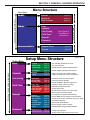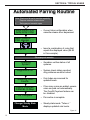
1
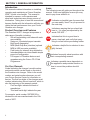
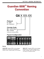
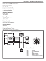
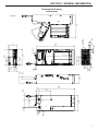
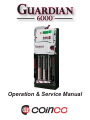
Operation & Service Manual
TABLE OF CONTENTS
SECTION 1: GENERAL INFORMATION
Introduction
Document Icons
Naming Convention
Dimensions & Specifications
Dimensional Drawing
4
4
5
6
7
SECTION 2: INSTALLATION & SETUP
Unpacking/Installing the Changerr
Loading Coins
Dispensing Coins
Setting Float
8
10
11
12
SECTION 3: GENERAL CHANGER OPERATION
Steady State User Display
General Changer Operation
Menu Navigation
Menu Structure
13
1
13
15
1
15
1
SECTION 4: TYPICAL USAGE
Parring the Guardian
Setting Float
Enabling/Disabling Overfill Paydown
Float Paydown
Audit Reporting
Changing the Payout Coin Tube
Configuration
Cassette Configuration
Eliminating a Slug
Adding a Token
Deleting a Token
Token Change Value
Token Change Routing
Optimal Float Recomendations
Service Recomendations
21
24
25
26
26
27
27
28
28
SECTION 5: ADVANCED CONFIGURATION
Password
Changing the Password
Password Protection Levels
Coin Enable
Dual Currency
Change Management
Coin Security Level
Language
Clear Historical Audit
Factory Reset
Disable/Enable Audible Feedback
29
29
30
31
32
33
3
34
35
3
35
35
3
36
17
19
19
1
19
1
20
MDB Level
36
SECTION 6: MAINTENANCE
Routine Maintenance
Disassemblyy
37
37
SECTION 7: TROUBLESHOOTING
Autotest
Warning Messages
Troubleshooting Matrix
42
43
4
45
4
SECTION 8: PARTS LIST
Guardian 6000™ Housing & Payout Cassette
Release Latch Assemblyy
Guardian 6000™ Chassis
Guardian 6000™ Payout Assembly
Guardian 6000™Payout Cassette Assemblyy
Guardian 6000™ Acceptor Assembly
Front View
w
Guardian 6000 ™ Acceptor Assembly
Back View
w
46
47
4
48
4
49
50
51
3
SECTION 1: GENERAL INFORMATION
Introduction
This manual contains information on installing,
operating and maintaining a Coinco Guardian
6000™ model coin changer. This manual is
intended for owners, route operators and
shop-level technicians as a primary source of
information. Taking time to read this manual and
become familiar with the information will help you
obtain the best performance from your Coinco
Guardian coin changer.
Icons
The following icons will guide you throughout the
manual. Each icon highlights an area you may
want to pay closer attention to.
Indicates a checklist type of process that
you can readily “check” as you proceed to
the next step.
Indicates a warning that you should adhere to. It is often accompanied by the
words “DO NOT…”
Product Overview and Features
The Guardian 6000™ changer incorporates a
wide range of benefits, including:
•
Six self-replenishing coin tubes with cash
accountability.
•
Swing-out, illuminated payout cassette.
•
Built-in self diagnostics.
•
MDB (Multi-Drop Bus) interface (optional
MDB to USB converter available).
•
Field tuning for tokens & slug elimination.
•
Interchangeable coin tubes enable simple
payout re-configuration.
•
Full support of Guardian features and
upgrades using the Coinco FP-5 Field
Programmer
For Your Records
A label indicating the changer’s model number
and serial number can be found on the side of
the Guardian coin changer. Refer to the model
number and serial number whenever you call
your Coinco Service Center for information or
service. The first four digits of the changer serial
number indicate when the unit was built, which is
also the beginning of the warranty period:
•
First two digits: indicate the week of
manufacture.
•
Third and fourth digit: indicate the year.
For example, serial number 1507000123 indicates the unit was manufactured in the 15th
week of 2007.
4
STOP
Indicates that this is a good time to
pause, step back, and verify that everything is correct before proceeding further.
Indicates a helpful hint or shortcut to simplify the task.
Indicates frequently asked questions with
their corresponding answers.
i
Indicates a possible issue dependent on
the application and provides direction on
how to correct the problem should it
occur.
SECTION 1: GENERAL INFORMATION
Guardian 6000™ Naming
Convention
G6 X XX-XX
Protocol
X = MDB
A = Protocol A
Country Code
US = United States
CA = Canada
Additional countries available.
Payout Configuration
Cassette
ID
BB
BD
BE
BF
Coin Denomination By Tube Position
Country
US
A
25¢
US / Canada $1
Canada
$2
Canada
$2
B
C
D
E
F
10¢
$1
$1
$2
5¢
25¢
25¢
$1
5¢
5¢
5¢
5¢
25¢
10¢
25¢
25¢
25¢
25¢
25¢
25¢
Please contact your Coinco Sales Rep for additional configurations.
Models
G6XUS-BB: Guardian 6000 six tube changer,
MDB protocol, “BB” payout configuration (2
nickels,1 dime, 3 quarter tubes), for US market.
G6XCA-BF: Guardian 6000 six tube changer,
MDB protocol, “BF” payout configuration (1
nickel, 2 quarters, two $1 coin tubes, one $2
coin tube), for Canadian market.
5
SECTION 1: GENERAL INFORMATION
Dimensions and Specifications
Power Requirements:
20 to 42V DC
0.15 Amp average standby
0.6 Amp average operating
1.8 Amp max operating
Operating Temperature
0°F to 150°F
-18°C to 65°C
Storage Temperature
-22°F to 160°F
-30°C to 72°C
Relative Humidity
20% to 95% non-condensing
Operating Attitude
Vertical ±3°
Shipping Weight in Carton
Approximately 5 lbs. or 2.267 kilograms
Figure 1
Controller/Vendor Interface
G6X
MDB Coin Changer Plug
Connect Pin-out:
Line 1
Line 2
Line 3
Line 4
Line 5
Line 6
6
34 VDC
DC Power Return
N/C
Master Receive
Master Transmit
Communications Common
3X O .500
(12.70)
3X .250
(6.35)
2.690
(68.33)
5.367
(136.32)
2.390
(60.70)
13.200
(335.28)
4.490
(114.05)
3X O .211
(5.37)
1.538
(39.07)
3.032
(77.01)
.600
(15.24)
2.249
(57.13)
.473
(12.00)
.921
(23.39)
1.300
(33.02)
.487
(12.38)
3.150
(80.01)
1.003
(25.47)
5.557
(141.15)
5.467
(138.86)
3.052
(77.52)
COIN PAYOUT AREA
AND
COIN RETURN AREA
2.410
(61.22)
2.569
(65.25)
1.320
(33.53)
.767
(19.49)
1.450
(36.83)
.238
(6.05)
.320
(8.13)
CASH BOX
CHUTE AREA
14.000
(355.60)
3.170
(80.51)
7.755
(196.97)
SECTION 1: GENERAL INFORMATION
Dimensional Drawing
inches (mm)
Figure 2
7
SECTION 2: INSTALLATION & SETUP
Unpacking / Installing the Changer
After removing the coin changer from the shipping carton, inspect it for possible damage. If
the unit is damaged, notify the shipping company
immediately. The consignee (person or company
receiving the unit) can file a claim against the
carrier for shipping damage. We recommend
you keep the original carton and packaging materials to reuse if you need to transport or ship
the coin changer in the future.
If the coin changer is being stored or used as a
spare, always keep it in its shipping carton when
not in use. This will keep it clean and offer the
best protection for the unit.
Installing the Changer
1.
2.
3.
4.
5.
6.
8
Remove power from the vending machine.
DO NOT connect the changer harness
to the vending machine with power
connected.
Remove the acceptor from the changer
housing by pressing the acceptor latch
(see Figure 4) on the front of the acceptor
and pull the escrow lever towards you,
away from changer housing.
Disconnect the acceptor’s ribbon cable
from the changer housing (see Figure 5).
Lift the acceptor slightly to free the lower
acceptor studs from the changer housing.
Place the acceptor in a clean, dry area.
Set the three mounting holes in the back
of the changer housing over the mounting
screws in the vending machine (see
Figure 6). Tighten securely by hand.
Re-install the acceptor by inserting the
lower acceptor studs into the changer
housing. Plug the acceptor ribbon
cable into the changer housing. Press the
top of the acceptor into the changer
housing until the acceptor latch engages
the changer housing.
Verify the vendor’s coin return
mechanism is adjusted to that the
Acceptor gate is fully closed. There
should be a small gap between the coin
return mechanism and the changer
escrow lever.
Changer Components
IRDA Link
Acceptor Gate
Escrow Lever
LCD Display
Acceptor
Release Latch
User
Interface
Keypad
Sorting Door
Acceptor
Docking
Cradle
Coin
Denomination
Markings
Payout
Cassette
Release Latch
Sorting Door
Latch
External
Data Port
Graduated
Tube Scales
Swing-out
Payout
Cassette
Access
Figure 3
Escrow Lever
Acceptor
Release
Latch
Figure 4
SECTION 2: INSTALLATION & SETUP
7.
STOP
8.
9.
Plug the changer harness into the vending
machine.
Verify steps 1 to 7 are completed
correctly.
Apply power to the vending machine.
The changer will power up, perform an
auto-test of all systems, then the
display will begin cycling in steady
state mode. See Figure 7 .
Figure 5
Power Up Sequence
Figure 7
Typical User Display Messaging
Guardian 6000
•
Intro screen.
SW: v0.1.1 MDB
HW: v1
•
Shows current versions of
software and hardware.
Checking
Diagnostics
•
Performs self-diagnostics of
systems. If there are errors,
recommendations are given.
Diagnostics OK
•
Self-diagnostics completed and
all systems are functional.
D05¢ E25¢ F25¢
A25¢ B10¢ C05¢
Float Mode Off
Status: OK
Tubes = $29.15
Loop
Float Disabled
Float Mode On
Status: OK
Tubes = $29.15
Loop
Add $4.85
Float = $34.00
Steady State Mode
See Figure 17 for an explanation of Steady State Mode messages.
Note: Some Guardian models may show different messaging.
Figure 6
9
SECTION 2: INSTALLATION & SETUP
Loading Coins
See Figure 10 for coin capacities.
10.
Load coins into the changer the tubes
using one of the following 3 options:
•
Using Swing Out Payout Cassette:
Rotate the Payout Cassette
Release Latch downward to open
the coin Payout Cassette (See
Figure 8). Pivot the Payout
Cassette out of the changer
housing to access the coin
tubes (See Figure 9). Once
the latch has been depressed,
the Payout Cassette must be at
least partially opened before
it can be closed and reset properly.
Fill the six coin tubes to the desired
levels with the appropriate coins.
Refer to the individual labels at the
top of the tube determine which
coin denominations go in
each tube.
•
By Removing Cassette: The
cassette can also be lifted out of
the changer for loading coins.
Open the Payout Cassette and
swing it out, then lift the Payout
Cassette straight up to remove it
(See Figure 11). Load coins as described above. Reinstall the
Payout Cassette by first positioning
it on the upper pin, then align the
lower pin and lower the cassette
•
To Load Front Tubes Only: Tubes
A,B, and C can be hand loaded
without opening the cassette. By
pushing the Sorting Door Latch to
the left and swinging open the
Sorting Door (See Figure 12), you
can load coins directly in tubes A,
B, and C.
NOTES:
• Make sure all coins lay flat and fill each coin
tube to be used with at least 5 coins.
• For the most reliable operation, do not load
coin tubes above the 100% level marking.
• If not using all 6 tubes, leave all tubes installed and make sure to disable coin routing and coin level sensing for unused tubes.
Use MENU/SETUP/CASSETTE/CUSTOM and
set unused tubes to “---”.
Figure 8
Payout
Cassette
Release
Latch
Figure 9
10
SECTION 2: INSTALLATION & SETUP
Coin Tube Capacities
Figure 10
Country
US
Canada
Coin
Type
Max Coin Count
5¢
10¢
25¢
$1
5¢
10¢
25¢
$1
$2
Qty.
80
111
81
67
80
121
88
68
79
12.
Drop a variety of coins into the
changer to ensure proper operation.
Basic keypad navigation is shown in Figure 14
and a coin payout mode summary in Figure 13.
$
$4.00
$11.10
$20.25
$67.00
$4.00
$12.10
$22.00
$68.00
$158.00
Coin Payout Modes
Manual Payout
Normal Mode
Payout one or more
coins from a tube
Keystrokes
Hold down alpha key until
desired coins are paid out.
Auto Paydown Mode
Payout ALL coins in a
tube
Figure 11
Figure 13
Pause / Resume
Coin Payout
Stop Coin Payout
Keystrokes
Hold down alpha key until at
least 4 coins are dispensed.
Press Escrow Lever.
Press any key.
Note: The last several coins in a tube can be paid out with
individual button pushes.
Does the changer pay out all coins from
tubes or leave hidden coins? How are
hidden coins reported?
Figure 12
Sorting
Door
Latch
As is typical with most changers, the
Guardian leaves some hidden coins per
tube (usually 3-5) to ensure incoming
coins will always stack properly. These
coins can be paid out in a manual payout
mode. Hidden coins are not reported on
MDB and are not available for
change making. They are reported in
audit information and are used in all tube
scanning and float/par calculations.
Figure 14
Right Arrow: Move across
screen or selects current item.
Up/Down Arrows: Shows
options are available
above & below “Audit”.
Upper Level Menu:
Current Menu: Lower
case for this menu.
Dispensing Coins
Verify proper payout operation
11.
Pay out at least two coins from each
tube to ensure proper operation. Press
each coin tube Inventory Button (See
Figure 9) to dispense coins.
MAIN MENU
Audit
▲
▼
Up Arrow: Scroll
up in current menu.
Left Arrow: Go back
one menu level.
Inventory Buttons
(Letters): For coin
tube or password
actions.
CANCEL: Exit out
of operation, or go
up one menu level.
Down Arrow:
Scroll down in
current menu.
ENTER: Select current
item or accept/close
operation.
11
SECTION 2: INSTALLATION & SETUP
Setting Float (optional)
Float Mode records and maintains a predefined level of coins in the tubes, and typically will
maintain a lower level of change in the changer than if Float mode is not used. When using
Float mode, an accepted coin will only be routed to the tube if one has been paid out.
13. You can quickly Enable Float at the current coin levels by simultaneously pressing the keypad
hotkeys E+F. Then press ENTER to accept the displayed Float Value.
14. To disable or reset Float level, simultaneously press keypad hotkeys D+F to Disable Float.
Adjust the coin levels and repeat step 12 above.
When I add coins prior to resetting my float level, the changer automatically kicks coins
out. Why?
Overfill Paydown automatically returns any coins that exceed the Float Mode level. Any coins added to
the coin tubes after parring, or adding coins prior to setting a higher Float level will result in these extra
coins being sent to the coin return. See Step 14 above for how to Disable Float.
Figure 15
1.
2.
3.
4.
5.
Setting Float
Push D+F to Disable Float.
Open cassette and load desired level of coins for float.
Close cassette and wait for steady state operation (cycling display).
Push MENU button.
Press E+F to Enable Float. Or, scroll using arrow keys to the
screen below
Cancel
SETUP
Float
12
▲ Enter
▼
FLOAT
▲ Enter
Set Float
▼
▲
Scroll
▼
FLOAT
▲ Enter
Disable Float ▼
Scroll ▲
▼
FLOAT
▲
Overfill Paydn ▼
Scroll ▲
▼
FLOAT
▲
Float Paydn ▼
Scroll ▲
▼
Scanning
Tubes
Float Disabled
Float = $XX.XX
CANCEL or ENTER
Enter
Float Set To
$XX.XX
Changer
Steady State
Mode
SECTION 3: GENERAL CHANGER OPERATION
Steady State User Display
During steady state operation, the user display will show one of four typical screens as shown in
Figure 16.
Steady State Operation
Display Messages
Figure 16
Fully Functional
Changer Problem
Option 1:
1 Float Enabled
Option 3: Warning
Status: OK
Tubes = $29.15
Loop
Add $4.85
Float = $34.00
• $29.15 change in tubes.
• Float set at $34.00.
• Add $4.85 to Par changer.
Option 2:
2 Float Disabled
Status: OK
Tubes = $29.15
Loop
Float Disabled
• $29.15 change in tubes.
• Float mode not used.
General Changer Operation
Acceptor Module
The Acceptor Module contains the majority of the
Guardian’s control logic. The Acceptor can electronically validate up to 32 different coin types
and actively route accepted coins to any of six
coin tubes or to the vending machine cashbox.
A LCD display provides visual feedback on the
functioning condition of the changer. Six inventory buttons allow the user to manually dispense
coins from the coin tubes. The MENU button
allows access to enter special programming and
features.
The Acceptor Module transmits credit and status information and receives payout and control
information from the vending machine. The Acceptor monitors each coin tube to know when it is
full so any additional coins can be routed to the
Status: Warning
Tubes = $29.15
Loop
Float Disabled
Loop
Warn 1: Clean
Acceptor
• Warning(s) & recommended
user action(s) displayed.
Option 4: Out of Service
Out of Service
• Changer non-operational
and requires immediate
attention.
Coin Acceptance
Deposited coins enter the coin inlet funnel, where
they are directed down a coin rail formed by the
mainplate and acceptor gate. Optical and magnetic sensors positioned along the rail validate
the coins. When the coin reaches the end of the
coin rail, motor and solenoid-operated coin doors
direct the coins to either the coin tubes, cashbox
or to the coin return chute.
Pressing the escrow lever physically opens the
acceptor gate, allowing bent coins and foreign
materials to fall into the coin reject chute. Movement of the front gate is also detected by the coin
changer electronics and is communicated to the
vending machine controller causing any customer
credit to be paid back.
If coins are deposited too closely together (fast
feed), one or more coins may be rejected if the
13
SECTION 3: GENERAL CHANGER OPERATION
Coin Tube Cassette
The coin cassette contains the six coin tubes that
store coins for change payout. The front and
back halves of the cassette hinge together to
form the coin return chute. Rejected coins from
the acceptor pass through the center of the cassette assembly and fall out the bottom of the coin
changer. Accepted coins are guided into the coin
tubes.
Payout Module
The bottom of the Guardian changer is the Payout Module. Coins stored in the coin tubes of the
cassette are dispensed by the payout modules
motor driven belt. The belt has two pins attached
to it, which engage a sweeper at the bottom of
each coin tube. When the sweeper is engaged,
one coin is released from the coin tube. The acceptor module sends information to the payout
module for dispensing coins from the cassette.
Pulse-Echo Coin Sensing Techonology
RETURN
Housing Module
The Housing Module consists of the changer
housing, MDB harness and changer board. The
backside of the housing has three mounting
holes for attaching the Guardian changer to the
vending machine. The cashbox coin chute is
also part of the housing.
Coin Level Sensing
The Pulse-Echo coin level sensing method emits
and detects sound waves. The number of coins
is calculated by the amount of time it takes the
emitted sound wave to deflect off the coin stack
and return to be detected. (See Figure 17)
EMIT
acceptor cannot safely route them to the appropriate coin tube. When any object (coin, counterfeit coin, etc.) is rejected, the changer will temporarily delay coin validation to allow the rejected
object to exit the changer.
Figure 17
How often does the changer scan the
tubes?
The Guardian will automatically scan
after any coin deposit or payout. It will
also scan after any “change in state”,
e.g. when the payout cassette or
sorting door is opened then closed.
I added one coin to a tube and the coin
level sensing did not detect it. Why?
The Pulse-Echo coin level sensing method
is accurate to within ±2 coins. It may not
necessarily detect a difference when a
single coin is added. This is normal and is
within the technology’s margin of error.
Does the Guardian require tube sensing
calibration as with other models?
No, it does not require any calibration to
attain its level of accuracy.
14
SECTION 3: GENERAL CHANGER OPERATION
Menu Navigation
The following views summarize menu navigation for the Guardian 6000 changer:
•
General menu navigation and keypad functionality is shown in Figure 13.
•
The special “hotkeys” to streamline key operations are shown in Figure 18.
Figure 18
(any individual
alpha key)
Guardian “Hotkeys”
:Displays coin denomination and quantity for
the selected tube (A-F). Also used for manual
payout.
(1 push): Accesses Main Menu.
(2 pushes): Begins Audit Current Data
reporting.
+
+
+
+
: Establishes float at current change level.
: Disables Float mode.
: Shows Payout Cassette coin configuration.
: Initiates Float Paydown (if enabled).
Menu Structure
The main menu consists of three primary functions: 1) Audit capabilities 2) Changer Setup, and
3) Recommendations. The overall menu layout is shown in Figure 19. This figure is also your guide
showing where each menu topic is reviewed in this user manual. Figure 20 shows more information
specifically on the Setup menu.
What happens if I do not complete a programming change and walk away mid-stream?
For safety purposes, the Guardian times out if a programming step is not completed. It will
then default to the prior settings.
15
SECTION 3: GENERAL CHANGER OPERATION
Figure 19
Menu Structure
Main Menu
Audit
Current ……………………..page 20
Clear Current ………...……. page 20
Setup
Float
Cassette
Coin Config
Field Tune
See Figure 21
for additional
information
General
Scroll within menu
Scroll up / down using arrow keys
Historical …….…………… page 20
Password
Recommendations
Optimal Float …………….. page 28
Service ……...…………….. page 28
Scroll up / down using arrow keys
Setup Menu
Float
Cassette
Coin Config
Field Tune
General
Password
16
Setup Menu Structure
Set Float …...……...page 12
Figure 20
Disable Float …......page 12
Set / maintain predefined coin level.
Turn off Float Mode.
Overfill Paydn …....page 19
Enable (default) / disable Overfill Paydown.
Float Paydn………..page 19
Enable / Disable (default) Float Paydown.
Standard …..............page 24
Custom …................page 24
Assign coin routing for standard cassette.
Assign coin routing for custom configuration.
Coin Enable ….........page 31
Change Mgmt …......page 33
Security Level ……..page 34
Determine which coins are accepted.
Set change paying algorithm.
Enable Standard or High Security by coin.
Token Add …...........page 26
Token Delete ….......page 26
Token Chg Value …page 27
Token Chg Rtg ……page 27
Slug Remove ..........page 25
Add token, assign value and routing.
Delete previously loaded token.
Change token value.
Change routing (coinbox, coin return tube).
Block a slug from being accepted.
Autotest …..............page 42
MDB Settings …......page 36
Dual Currency …....page 32
Language …............page 35
Clear Hst Audit …...page 35
Factory Reset ….....page 35
Sound ….................page 36
Run autotest for changer troubleshooting.
Change MDB Level for changer communications.
Accept coins from two countries & which go to tubes.
Set baseline language.
Delete Audit Historical data.
Return changer to factory settings.
Disable/Enable changer audible feedback.
Chg Password …....page 29
Password Level …..page 29
Change user password.
Change password protection level for menu.
SECTION 4: TYPICAL USAGE
Now that you’ve installed and completed the basic setup of your Guardian 6000™ changer, this section will
review typical route operations. More detailed setup capabilities are detailed in Section 5.
Parring the Guardian
Parring is the action of bringing the changer back to its original float level. This can be accomplished either
via the Guardian’s automated parring system (when Float has been set by the user), or visually when Float
has not been set.
1.
Automated Parring System: The simplest way to par is by using the Guardian’s automated parring
recommendations. See Figure 21 for details.
If coins only need to be added to the front tubes, the Sorting Door can be opened instead of the payout
cassette. Otherwise, everything else is the same in Figure 21.
2.
Manual or Visual Parring: The Guardian can also be parred visually by refilling the tubes to the
approximate levels. This can be accomplished either by using the tube markings, or by using the
optional Guardian adjustable par rings. The Manual or Visual Parring methods are only to be used
when Float Mode is disabled.
•
Open the payout cassette (all tubes) or sort door (front tubes only) and load coins to the desired
tube level marking to the parring level.
•
Par rings can be adjusted to the desired level by sliding them up or down on the tubes.
17
SECTION 4: TYPICAL USAGE
Automated Parring Routine
Note: Float must be set to use this capability.
1.
Depress cassette release lever.
2.
Swing payout cassette open.
D05¢ E25¢ F25¢
A25¢ B10¢ C05¢
• Current tube configuration when
cassette release lever depressed.
Insert Coins to
PAR changer…
Loop
• Insert a combination of coins that
equals the displayed value ($4.85
in this example).
Add $4.85
Close payout cassette.
Checking
System
• Guardian verifies status of all
systems.
Diagnostics OK
• System check status reported.
Any problems would be noted.
Scanning Coin
Counts
• Coin tubes are scanned for
updated levels.
Overfill Paydown
CANCEL to Stop
Par Complete
Changer Steady State
Mode
• If too many coins are added, excess
coins are paid out automatically.
The Overfill Paydown feature can
be disabled.
• Par routine is complete.
• Steady state mode “Tubes = “
displays updated coin levels.
Figure 21
18
SECTION 4: TYPICAL USAGE
Setting Float (optional)
See Section 2: Installation & Setup.
Enabling / Disabling Overfill Paydown
When the changer is in Float Mode, the Overfill Paydown feature causes the changer to pay out any
coins in excess of the Float level that are inserted during parring. Overfill Paydown is defaulted to
“on” in the standard changer setup.
See Figure 22 for how to turn this feature on or off.
Disabling / Enabling: Overfill Paydown &
Float Paydown
1. Push MENU Button.
2. Scroll using arrow keys to screen below
Enter for
SETUP
Float
▲ Enter
▼
FLOAT
Set Float
OVERFILL PAYDN ▲ “ON”
▲
▼
Enable
Scroll ▲
Scroll ▲
▼
▼
FLOAT
Disable Float
Scroll ▲
▼
FLOAT
Overfill Paydn
Enter for
OVERFILL PAYDN ▲ “OFF”
▲
▼
Disable
▼
Changer
Steady
State
Mode
Scroll ▲
▼
▲
▼ Enter
Scroll ▲
▼
FLOAT
Float Paydn
▼
Enter for
FLOAT PAYDN
Enable
Enter
Scroll ▲
▼
▲ “ON”
▼
Scroll ▲
▼
FLOAT PAYDN
Disable
Scroll ▲
▼
Enter for
▲ “OFF”
▼
Changer
Steady
State
Mode
Figure 22
Float Paydown
When the changer is in Float Mode, the Float Paydown feature causes the changer to route all accepted coins to the tubes until they are full; the balance then go to the cashbox. Float Paydown is
commonly used to ensure the maximum change making capability is always available without having
to manually fill the changer during the route visit. Float Paydown is defaulted to “off” in the standard
changer setup.
See Figure 22 for how to turn this feature on or off.
19
SECTION 4: TYPICAL USAGE
Audit Reporting
The Guardian features a means of tracking and reporting all sales. Audit data consists of two types
of data: 1) Current Data, and 2) Historical Data.
1.
Current (Resettable) Data: consists of changer data stored since the last user reset. See
Figure 23 for details.
The user can quickly begin Audit Current Data reporting by pushing MENU twice. Refer to
Figure 18 for additional information on changer hotkeys.
2.
Clear Current (Resettable) Data: Clears all changer data since the last user reset. Current
data can be cleared at any time. See Figure 23.
How are ‘Exact Change Losses” calculated?
Historical sales activity is used to calculate lost sales when in the exact change mode.
How are ‘Total Sales’ quantities and dollar values calculated?
Every transaction where coins are accepted at or above the predefined vend price equates to
a quantity of one sale. The sum of these sales is the total sales in dollars.
Figure 23
1.
Audit Reporting / Clear Current Data
Scroll using arrow keys to screen below
MAIN MENU
Audit
▲ Enter
▼
AUDIT
Current
▲
▼
Enter
Scroll ▲
Scrolls automatically….
Cash to Cashbox
= $53.75
▼
AUDIT
Historical
▲
▼
Enter
▲
▼
Enter
Scroll ▲
▼
AUDIT
Clear Current
Scroll ▲
▼
Cash to Tubes
= $23.15
Change Dispensed
= $25.45
Manual Dispense
= $2.35
Total Sales
Qty = 83
Navigation Keys – Within Audit
ENTER = Pause / Resume.
▲ = Scrolls within screens.
▼
20
Token Sales
Qty = 4
Exact Chg Sales
Qty = 1
Total Sales
= $83.00
Exact Chg Sales
= $1.25
Exact Chg Losses
= $4.15
Time in Exact Chg
= 5%
End Audit
Total Coins Paid
Qty = 132
Coins Accepted
Qty = 456
Changer
Steady State
Mode
SECTION 4: TYPICAL USAGE
3.
Historical Data: consists of data stored since the changer was first put in service. Audit
Historical Data displays the same categories of data as Current Data, the totals will just be
from the beginning of the changers service life. See Figure 23 for details.
Historical Data can also be reset for extreme cases where the user does not want their sales
data to be revealed; e.g. changer is being sold, etc. See Figure 44 for more information.
Changing the Payout Coin Tube Configuration
Your Guardian will typically incorporate a Standard Cassette configuration (See Figure 24). The
Guardian features the capability of changing individual tubes within the payout cassette.
The Guardian coin tube locations are designated as shown in Figure 25.
Guardian 6000™ Standard Cassettes
Cassette
ID
BB
BD
BE
BF
Coin Denomination By Tube Position
A
Country
US
25¢
US / Canada $1
Canada
$2
Canada
$2
B
C
D
E
F
10¢
$1
$1
$2
5¢
25¢
25¢
$1
5¢
5¢
5¢
5¢
25¢
10¢
25¢
25¢
25¢
25¢
25¢
25¢
Please contact your Coinco Sales Rep for additional configurations. Figure 24
Payout Cassette - Coin Tube Position Designations
D
E
F
Coin Return
A
B
C
Changer Top View
Figure 25
21
SECTION 4: TYPICAL USAGE
Payout Cassette - Coin Tubes & Positions
$2
$1
25¢
5¢
10¢
Tube #1
Tube #2
Tube #3
Tube #4
Tube #6
AB
ABC
ABCDEF
ABCDEF
ABCDE
Coin
NA
US $1
US 25¢
US 5¢
US 10¢
Tube Assy # /
Shim Color
NA
408832-1
Lt. Gray
408833-1
Blue
408834-1
Blue
408836-1
Red
Possible Tube Positions
US
Canada
Coin
CAD $2
CAD $1
CAD 25¢
CAD 5¢
CAD 10¢
Tube Assy # /
Shim Color
408831-1
Black
408832-1
Lt. Gray
408833-2
Black
408834-1
Blue
408836-2
Gold
Note: Coin tube numbers (e.g. Tube #2) are marked on the back of the tube by the shim attach point.
Changing the Coin Tubes
There are 5 different tube sizes for the North
American market. Quarter and nickel tubes can
be placed in any of the six payout positions (See
Figure 25). Tubes for dimes, $1 and $2 coins
have restrictions on their placement. Please refer
to Figure 26 for details.
Each coin tube will require a specific coin shim in
order to accurately pay out that coin thickness.
Please refer to Figure 26 to ensure the correct
coin shims are installed.
1.
Rotate the Payout Cassette Release
Latch downward to open the coin payout
cassette. Refer to Figure 27.
2.
Pivot the payout cassette out of the
changer housing by pulling on its lower
right corner (See Figure 28). Once the
latch has been depressed, the payout
cassette must be at least partially opened
before it can be closed and reseated
properly.
3.
Lift the cassette straight up to remove it
from the coin changer (See Figure 29).
4.
To remove an individual coin tube,
hold the cassette assembly then
gently pull the top of the coin tube
forward to unsnap the top of the
tube. See Figure 30.
5.
Tilt the top of the tube away from
the cassette and lift the tube out.
22
6.
7.
Figure 26
See Figure 31.
Install the replacement coin tubes and
shim assembly by first inserting the bottom of the tube in the cassette, then pivot
the top of the tube and snap it into the upper part of the cassette. Check that all
coin tubes are secured to the cassette.
Reinstall the payout cassette into the
housing.
Programming the Coin Routing
Whenever the coin tubes are changed, the
Guardian must be reprogrammed to route coins
to the new tube locations. See Cassette Configuration - Using a Custom Configuration.
Payout
Cassette
Release
Latch
Figure 27
SECTION 4: TYPICAL USAGE
Figure 30
unsnap
Figure 28
Figure 31
Figure 29
23
SECTION 4: TYPICAL USAGE
Cassette Configuration
Cassette configuration assigns which coins route to which payout tubes.
Your new Guardian changer will already be configured for the factory cassette and coin routing. This
step of changing the cassette configuration is only necessary if:
•
a payout cassette has been replaced with a cassette containing different coin tubes, or coin
tubes in different positions.
•
individual coin tubes have been replaced (or moved).
There are two ways to assign coins: 1) Using a Standard Cassette, or 2) Using a Custom
Configuration.
1.
2.
Using a Standard Cassette: Figure 24 shows the Standard Guardian payout configurations.
If you are using a Standard cassette, find the cassette configuration designation (such as BB,
BD, etc. in Figure 24) and proceed to Figure 31 to enter this cassette configuration. The
Using a Custom Configuration: a custom configuration is any combination of tubes and/or
coin routing other than what is shown in Figure 25. If you want to reconfigure the
payout tube configuration and have not already done so, please refer to Changing the Payout
Coin Tube Configuration before proceeding. After this has been done, you will need to
reconfigure the coin routing. See Figure 32 below.
If you do not plan to use all 6 coin tubes, leave tubes installed and make sure to disable coin
routing and coin level sensing for the appropriate tubes. This is done by entering “---“ when
assigning coins; see Figure 32 below for an example.
i
On some Vendo and Dixie-Narco machines, certain changer setup modifications (tube reconfiguration, changing coin routing, token additions/deletions) may not be recognized. If this occurs,
cycle power to the main controller board to correct the problem.
Tokens cannot be routed to tubes using the Custom Cassette menu. The Token Routing
menu should be used.
Changing Cassette / Tube Configuration
1.
2.
Push MENU button.
Scroll using arrow keys to screen
below
SETUP
Input Standard
cassette designation
▲
▼
Cassette
Shows configuration
for entered cassette.
Enter
CASSETTE
Standard
Scroll ▲
▼
CASSETTE
Custom
Scroll ▲
▼
▲ Enter Standard
▼
Cassette I.D. BB
▲ Enter Select Tube(s)
▼
& Assign Coin
Enter D05¢ E25¢ F25¢
A25¢ B10¢ C05¢
◄ ►Assign Tubes;
▼▲ Assign Coins
To Accept
Press ENTER
D25¢ E25¢ F- - A25¢ B05¢ C10¢
Loop
Select tube by using Right/Left
arrows; Select coin for each tube by
scrolling using Up/Down arrows.
Scrolling to & selecting “- - -” will
disable coin routing and tube
scanning for that position
24
Loop
To Accept All
Press ENTER
Enter
Changer
Steady
State Mode
Enter
Figure 32
SECTION 4: TYPICAL USAGE
Eliminating a Slug
Slugs are counterfeits or foreign coins that are used by thieves to gain credit for a higher value domestic coin. The Guardian enables simple blocking of slugs while the changer is still on site.
Slugs can easily be blocked by completing the simple field tune in Figure 33. You will need at least
one sample of the slug to be blocked to tune the changer. Eliminated slugs can be routed to the
cashbox to prevent thieves from re-using them.
Figure 33
Eliminating A Slug
1. Push MENU button.
2. Scroll using arrow keys to screen below
SETUP
Field Tune
Dropping 10 examples
gives better accuracy.
▲
▼
Drop 10 Times
Enter
FIELD TUNE
Token Add
Scroll ▲
▼
FIELD TUNE
Token Delete
Scroll ▲
▼
FIELD TUNE
▲
▼
▲
▼
▲
Token Chg Value▼
Scroll ▲
▼
FIELD TUNE ▲
Token Chg Rtg ▼
Scroll ▲
▼
FIELD TUNE ▲
Slug Remove ▼
Enter
Scroll ▲
▼
Decrements to 0.
Drop 9 Times
Tune
Established
Drop
Complete
Cash Box
Scroll ▲
▼
▼
Slug Removed
SLUG ROUTING▲
Coin Return
Scroll ▲
▼
Creating Tune
Success
Failure
SLUG ROUTING▲ Enter
▼ Enter
Changer
Steady
State Mode
Tune Failure.
Redrop
25
SECTION 4: TYPICAL USAGE
Working with Tokens
The Guardian 6000™ features a wide range of token capabilities all of which can be accomplished
while the changer is still on location. These capabilities are covered here.
All token capabilities listed in this section can also be accomplished using the Coinco FP-5
Field Programmer.
Adding A Token
Enables acceptance of a token.
Tokens can easily be added while the changer is still on site by completing the simple field tune in
Figure 34.
If free value tokens are routed to tubes, the user must ensure the proper tube/shim combination is
used to allow reliable token payout. Please contact Coinco with token diameter and thickness
measurements for a coin tube/shim suggestion
i
On some Vendo and Dixie-Narco machines, certain changer setup modifications (tube reconfiguration, changing coin routing, token additions/deletions) may not be recognized. If this occurs,
cycle power to the main controller board to correct the problem.
Adding / Deleting A Token
1. Push MENU button.
2. Scroll using arrow keys to screen below
SETUP
Field Tune
▲
▼
Tune
Established
Drop 10 Times
Assign Name
Enter
FIELD TUNE
Token Add
Scroll ▲
▼
FIELD TUNE
Token Delete
Scroll ▲
▼
FIELD TUNE
▲
▼ Enter
▲ Enter
▼
▲
Token Chg Value▼
Scroll ▲
▼
FIELD TUNE ▲
Token Chg Rtg ▼
Scroll ▲
▼
FIELD TUNE ▲
Slug Remove ▼
Scroll ▲
▼
Figure 34
Decrement
Count
Scroll ▲
▼
Assign Value
Drop
Complete
Enter
▲ Enter TOKEN VALUE ▲ • Options: Free to $9.95.
▼
▼
TKN=FREE
Scroll ▲
▼
Assign Route
Creating Tune
Success
Scroll ▲
Failure
Tune Failure.
Redrop
Other tokens loaded
Delete Token
TKN 0
▼
▲ • Options are: 0 to 9.
▼ • Default is next available.
▲ Enter TKN 0
▼
Enter
▲ Enter TOKEN ROUTING ▲
▼
▼
Coin Return
Enter
Scroll ▲
▼
TOKEN ROUTING ▲
▼
Cash Box
Enter
Scroll ▲
▼
• Option of Tubes only if
TOKEN ROUTING ▲
Token Value = FREE.
▼
Tubes
• Must then assign tube.
Enter
Scroll ▲
▼
Field Tune
Complete
▲ Enter Token Deleted
▼
No other tokens
Changer Steady
State Mode
Deleting a Token
Allows the user to block acceptance of a previously tuned token.
See Figure 34 for how to delete a token.
On some Vendo and Dixie-Narco machines, certain changer setup modifications (tube reconfiguration, changing coin routing, token additions/deletions) may not be recognized. If this occurs,
cycle power to the main controller board to correct the problem.
i
26
SECTION 4: TYPICAL USAGE
Token Change Value
Change the value of a previously tuned token.
A token that is currently valued as “FREE” and routed to the changer tubes cannot be revalued
without first changing the routing to “Cashbox” or “Coin Return.”
See Figure 35 for how to change token value.
Token - Change Routing / Change Value
1. Push MENU button.
2. Scroll using arrow keys to screen below
SETUP
Field Tune
▲
▼
Enter
FIELD TUNE
Token Add
Scroll ▲
▼
FIELD TUNE
Token Delete
Scroll ▲
▼
FIELD TUNE
Allows scrolling if more than
one token is loaded.
▲
▼
TOKEN CHG RTG ▲ Enter
▼
TKN 0
TOKEN ROUTING ▲
Coin Return
Scroll ▲
▼
▲
▼
Cash Box
▼
Scroll ▲
▼
▲
Enter
TOKEN ROUTING ▲
Tubes
▼
Scroll ▲
▼
▲
▼ Enter
▲
▼
Enter
TOKEN ROUTING ▲
Token Chg Value▼
Scroll ▲
▼
FIELD TUNE
Token Chg Rtg
Scroll ▲
▼
FIELD TUNE
Slug Remove
Scroll ▲
▼
▼
• First screen shows
current setting.
• Scroll to desired
choice and ENTER
▼
Allows scrolling if more
than one token is loaded.
Enter
TOKEN VALUE ▲
▼
TKN=FREE
TOKEN CHG VALUE ▲ Enter
TKN 0
• Option of Tubes only if
Token Value = FREE.
• Must then assign tube.
• Options: Free to $9.95.
• Initial value is current.
Figure 35
Token Change Routing
Change the routing of a previously tuned token.
See Figure 35 for how to change the routing for a token.
If free value tokens are routed to tubes, the user must ensure the proper tube/shim combination is
used to allow reliable token payout. Please contact Coinco with token diameter and thickness
measurements for a coin tube/shim suggestion.
27
SECTION 4: TYPICAL USAGE
Recommendations
Optimal Float
This section offers helpful advice on getting the
most out of your Guardian 6000™ changer.
The Guardian 6000™ tracks a wide variety of
usage data to support the audit reporting feature.
This same data is used to develop the recommendations discussed in this section. There is
no better data than that from your specific
installation to help optimize changer operation.
The Recommendations section includes 1) Optimal Float, and 2) Service.
Displays the recommended Float level for the
changer based on the last 60 days of changer
usage.
The Optimal Float recommendation is based
on the most recent changer activity and thus will
vary slightly over time based on day-to-day transactions. To minimize the Exact Change condition
and maximize machine sales, it is recommended
that Optimal Float be checked every month or
so. The user can then update the Float setting to
obtain the optimal changer performance.
See Figure 36 for how to obtain the Optimal Float
Recommendation.
Service
Will automatically make a Service recommendation based on changer usage.
See Figure 36 for how to check for Service Recommendations.
Figure 36
1.
Recommendations
Scroll using arrow keys to screen below
Shows current Float setting
and recommended Optimal
Float setting based on recent
changer usage.
MAIN MENU
▲
Recommendations ▼
Enter
RECOMMENDATIONS ▲ Enter
Optimal Float
▼
Float
= $XX.XX
Optimal = $YY.YY
Scroll ▲
▼
RECOMMENDATIONS ▲ Enter
Service
▼
Recommend Coinco
Clean & Test
Scroll ▲
▼
28
Service Recommendations will
only be shown if the changer
has had significant usage
levels.
Changer
Steady
State
Mode
SECTION 5: ADVANCED CONFIGURATION
Advanced Configuration
This section explains the lesser-used features of the Guardian 6000™ changer.
Password
The password section protects the more sensitive changer information.
Entering the Password
A password must be entered any time the user attempts to enter a password-protected area of the
menu. These include the Password area of the Setup menu, as well as the areas defined by the
Password Protection Level (see below).
The basics of Password operation are as follows:
1.
The default Password for most changer configurations is D-E-F-B.
2.
The CANCEL button allows you to back up while typing the password, or to back out of the
Password screen entirely.
3.
Once the correct password is entered, it allows access to the user’s original destination.
4.
There is no penalty for multiple incorrect password attempts; i.e. the screen does not lock out
access to non-password protected items.
Changing the Password
Passwords can easily be changed from the default.
Valid passwords are four characters and are any combination of the letters D, E, F, and B (the four arrow keys). See Figure 37 for how to change the password.
If the password has been changed from the standard D-E-F-B, and the user cannot remember
what it is, the Password can be reset by using the Coinco FP-5 Field Programmer.
Password / Change Password & Level
1. Push MENU button.
2. Scroll using arrow keys to screen below
SETUP
Password
▲
▼
Cancel
PASSWORD
Chg Password
Enter
Incorrect
Incorrect
Password
▲
▼
▲ Enter
▼
Password = FEED
CANCEL or ENTER
Enter
Correct
Scroll ▲
▼
PASSWORD
Password Level
Scroll ▲
▼
First screen shows current
setting. Scroll to desired
Level and ENTER
▲ Enter PASSWORD LEVEL ▲
▼
LEVEL 1
▼
Scroll ▲
▼
PASSWORD LEVEL ▲
LEVEL 2
▼
Scroll ▲
▼
PASSWORD LEVEL ▲
LEVEL 3
▼
Scroll ▲
▼
Cancel
Enter Password
____
▲ Enter Enter Password
▼
FEED
Changer
Steady State
Mode
Enter
Enter LEVEL = LEVEL X
CANCEL or ENTER
Figure 37
29
SECTION 5: ADVANCED CONFIGURATION
Password Protection Levels
Password Protection Levels allow the user to decide which information is protected by a password.
The Guardian features three levels of password protection:
•
Level 1: The default, or lowest level of security.
•
Level 2: Adds Field Tuning and the entire Setup-General sections of the menu.
•
Level 3: Adds Float, Cassette Configuration, and Coin Configuration.
See Figure 41 for a visual representation of the Password Protection Levels. Figure 38 shows how to
change the level.
Password Protection Levels
LEVEL 3
LEVEL 2
LEVEL 1 (default)
All Password Items
• Password Level
• Change Password
• Factory Reset
• Clear Hist Data
Adds:
Adds:
Field Tune
General
Float
Cassette
Coin Config
Increasing Security
Figure 38
30
SECTION 5: ADVANCED CONFIGURATION
Coin Enable
Coin Enable allows the user to select which coins are and are not accepted within the standard coin
set for the country.
See Figure 39 for enabling and disabling acceptance of coins within the standard coin set.
The standard coin set for the country is determined by the changer “Country Code”. See the
Guardian Naming Convention (page 5) to determine the Country Code of the changer.
Figure 39
Coin Enable
1. Push MENU button.
2. Scroll using arrow keys to screen below
SETUP
Coin Config
▲
▼
Enter
COIN CONFIG
Coin Enable
Scroll ▲
▼
COIN CONFIG
Change Mgmt
Scroll ▲
▼
COIN CONFIG
Security Level
Scroll ▲
▼
▲ Enter Select Coins to
Enable / Disable
▼
Display shows current
status for each coin.
◄ ► Select Coin;
▲▼ Disable Coin
US25¢E US$1 D
US5¢ E US10¢E
Loop
▲
▼
To Accept All
Press ENTER
Enter
Changer
Steady State
Mode
31
SECTION 5: ADVANCED CONFIGURATION
Dual Currency
Allows coins from two countries to be accepted by the changer, and allows the user to set the routing
(cashbox or coin tube) for the coins.
See Figure 40 for how to enable acceptance of more than one country set of coins.
If Dual Currency is enabled, then you must select which coins are routed to the coin tubes and which
are routed to the cashbox. Figure 40 shows how to set which country set is routed to the coin tubes;
the other country’s coins are automatically routed to the cashbox.
Dual Currency / Coin Routing
1. Push MENU button.
2. Scroll using arrow keys to screen below
GENERAL
Dual Currency
▲
▼
Enter
ENABLE COINS
USD
Scroll to desired
choice and ENTER
Scroll to desired
choice and ENTER
▲
▼
Enter
Scroll ▲
▼
ENABLE COINS
CAD
▲
▼
Changer
Steady State
Mode
Scroll ▲
▼
ENABLE COINS
USD & CAD
Scroll ▲
▼
▲ Enter
▼
TUBE COINS
USD
Scroll ▲
Enter
▼
TUBE COINS
CAD
Scroll ▲
▼
32
▲
▼
▲
▼
Figure 40
SECTION 5: ADVANCED CONFIGURATION
Change Management
Allows the user to select the preferred method of paying change from the tubes.
The Guardian 6000™ offers three alternatives for satisfying change requirements:
1.
2.
3.
Least Coin Payout (default setting): Pays out the most possible coins from the highest
denomination tube coin available; then moves to the next lowest coin, and so on. By using the
highest denomination tube coins in a descending fashion, the least amount of coins are
paid out (best for consumer).
USD Alternate Payout: A payout algorithm specifically designed to optimize the payout of
change based on the U.S. coin set. By using a pre-defined set of rules, correct amounts can
be paid out even if the least denomination tube coin (nickels) are unavailable. If change
requirements cannot be satisfied using this criteria, the payout defaults to Least Coin Payout.
Standard Alternate Payout – A payout algorithm designed to optimize the payout of change
based on the existing coin tube levels in the changer. The algorithm will pay one of the
lowest denomination tube coins from a tube determined to be full and then resort to least coin
payout.
See Figure 41 for how to change the payout algorithm.
Figure 41
Change Management
1. Push MENU button.
2. Scroll using arrow keys to screen below
SETUP
Coin Config
▲
▼
Enter
COIN CONFIG
Coin Enable
Scroll ▲
▼
COIN CONFIG
Change Mgmt
Scroll ▲
▼
COIN CONFIG
Security Level
Scroll ▲
▼
▲
▼
▲ Enter
▼
CHANGE MGMT
Least Coin
Scroll ▲
▼
CHANGE MGMT
Std Alternate
Scroll ▲
▼
CHANGE MGMT
US Alternate
Scroll ▲
▼
First screen shows
current setting.
Scroll to desired
choice and ENTER
▲
▼
▲
▼
Enter
Changer
Steady State
Mode
▲
▼
33
SECTION 5: ADVANCED CONFIGURATION
Coin Security Level
Allows the user to determine how tight the acceptance rate should be for each type of accepted coin.
The Guardian 6000™ features two levels of security:
1.
Standard Security (default setting): accepts a coin at a minimum of 95% at normal
temperatures and changer installation tilts; extreme conditions are 90%.
•
High Security: is 90% and 80% respectively.
See Figure 42 for how to change the security level for each accepted coin.
Increasing the Coin Security Level for a coin from Standard to High Security will make it less
likely that a similar slug will be accepted, yet it will also reject a higher percentage of authentic
coins. It is recommended that the High Security setting only be used in specific instances to
deal with higher slug rates.
Coin Security Level
Figure 42
1. Push MENU button.
2. Scroll using arrow keys to screen below
SETUP
Coin Config
▲
▼
Display shows current
security setting for each coin.
Enter
COIN CONFIG
Coin Enable
Scroll ▲
▼
COIN CONFIG
Change Mgmt
Scroll ▲
▼
COIN CONFIG
Security Level
Scroll ▲
▼
34
Security Level
High / Standard
▲
▼
◄ ► Select Coin;
▲▼ Security Lvl
US25¢H US$1 H
US5¢ S US10¢S
Loop
To Accept All
Press ENTER
▲
▼
Enter
Enter
Changer
Steady State
Mode
SECTION 5: ADVANCED CONFIGURATION
Language
Language enables the user to change the user
interface LCD display language.
Clear Historical Audit
Stop This will delete ALL changer historical audit information.
Data cannot be restored after this step is completed.
See Figure 43 for how to change the default language.
1.
Scroll using arrow keys to screen below
Figure 44
The standard language is defined by the
changer “Country Code”. See the
Guardian Naming Convention (page 5) to
determine the Country Code of the
changer.
GENERAL
▲
Clear Hist Audit ▼
Enter
Cancel
CLEAR HIST AUDIT
Enter Password ▲
DEFB
▼ Correct CANCEL or ENTER
Enter
Incorrect
Incorrect
Password
Change Language
Changer
Steady State
Mode
1. Push MENU button.
2. Scroll using arrow keys to screen below
GENERAL
Language
▲
▼
Enter
LANGUAGE
English
Scroll ▲
▼
LANGUAGE
French
Scroll ▲
▼
LANGUAGE
Spanish
Scroll ▲
▼
▲
▼
First screen shows
current setting.
Scroll to desired
choice and ENTER
Factory Reset
Deletes all user settings and returns the changer
to the original as-new configuration.
STOP
▲
▼
Enter
Changer
Steady State
Mode
▲
▼
Factory Reset should only be used in
extreme cases since all user settings will be
deleted. Factory Reset does not reset
Audit Settings - those are cleared else
where. See Figure 45 for more information.
Figure 43
Figure 45
Clear Historical Audit
Clears ALL historical changer information that
resides in the changer.
STOP
Historical Data should only reset for extreme
cases where the user does not want their
data to be revealed; e.g. the changer is
being sold to a competitor, etc. See Figure
44 for more information.
Factory Reset
Stop This will delete ALL user settings and return the changer to
the original as-new configuration. Data cannot be restored
after this step is completed.
1.
Scroll using arrow keys to screen below
GENERAL
Factory Reset
▲
▼
Enter
Enter Password
DEFB
Cancel
Reset Changer
▲
▼ Correct CANCEL or ENTER
Incorrect
Incorrect
Password
Enter
Changer
Steady State
Mode
35
SECTION 5: ADVANCED CONFIGURATION
Disable / Enable Audible Feedback
Turns feedback sounds from the warning beeper “on” or “off.” The default setting is “on.”
Disable / Enable Sound
1.
Scroll using arrow keys to screen below
First screen shows
current setting.
Enter for
GENERAL
Sound
▲ Enter SOUND
Enable
▼
▲ “ON”
▼
Scroll ▲
▼
SOUND
Disable
Scroll ▲
▼
Enter for
▲ “OFF”
▼
Changer
Steady
State
Mode
Figure 46
MDB Level
Allows user to set the MDB communications level.
The Guardian 6000™ offers two MDB Level setting options:
1.
MDB Level 3 (default setting): this is the latest communications protocol and provides added
functionality. It is recommended for all equipment.
2.
MDB Level 2: this is an earlier protocol to support machines prior to the early 1990s that do
not communicate properly using the MDB Level 3 above.
See Figure 47 for how to change the MDB Level.
MDB Level
1.
Scroll using arrow keys to screen below
MDB SETTINGS▲ Enter LEVEL
Level
▼
Level 3
First screen shows current
setting. Scroll to desired
Level and ENTER
▲ Enter
▼
Scroll ▲
▼
▲ Enter
▼
LEVEL
Level 2
Changer
Steady
State
Mode
Scroll ▲
▼
36
Figure 47
SECTION 6: MAINTENANCE
Routine Maintenance
Routine maintenance will improve the performance and extend the life of your Guardian
changer while reducing the need for more involved repairs. Frequency of maintenance will
depend on environment and number of transactions.
Cleaning
The majority of your Guardian 6000 changer is
manufactured from high-quality industrial grade
plastic and should be cleaned with a warm water
and detergent solution.
CAUTION:
•
Never submerge the changer in water
•
Do not use petroleum solvents, steel wool,
scouring pads, or metal brushes for
cleaning.
•
Do not spray any part of the changer with
any type of lubricant.
Since all coins share a common inlet and coin
ramp, heavy usage or a dirty environment can
result in dirt build-up in the acceptor. Clean the
coin ramp by opening the acceptor gate to the
right. Hold the gate to prevent it from snapping
back. Wipe the exposed coin ramp and inner
surfaces with a damp cloth. For excessively dirty
units, use a damp cloth and mild detergent.
DO NOT SUBMERGE UNIT IN WATER!
Maintenance / Disassembly
Removing the Acceptor
1.
2.
Remove the acceptor from the changer
housing by pressing the acceptor latch to the
right on the front of the acceptor and then pull
the escrow lever towards you, away from
changer housing. See Figure 48.
Changer Components
IRDA Link
Acceptor Gate
Escrow Lever
LCD Display
Acceptor
Release Latch
User
Interface
Keypad
Sorting Door
Acceptor
Docking
Cradle
Coin
Denomination
Markings
Payout
Cassette
Release Latch
Sorting Door
Latch
External
Data Port
Graduated
Tube Scales
Swing-out
Payout
Cassette
Access
Escrow Lever
Figure 48
Acceptor
Release
Latch
Figure 49
Disconnect the acceptor’s ribbon cable from
the changer housing. Lift the acceptor slightly
to free the lower acceptor studs from the
changer housing. Place the acceptor in
a clean, dry area. See Figure 49
37
SECTION 6: MAINTENANCE
Removing the Coin Tube Cassette
3. Rotate the Payout Cassette Release
Latch downward to open the coin payout cassette. Pivot the payout cassette out of the
changer housing to access the coin tubes.
See Figures 50 & 51.
Figure 50
Payout
Cassette
Release
Latch
Figure 51
4.
38
Lift the cassette straight up off of the
double hinge to remove. See Figure 52.
Figure 52
SECTION 6: MAINTENANCE
Removing the Coin Tubes from the Cassette
5.
Figure 53
To remove an individual coin tube,
hold the cassette assembly then
gently pull the top of the coin tube
forward to unsnap the top of the
tube. Tilt the top of the tube away
fromthe cassette and lift the tube out. See
Figures 53 & 54
unsnap
Figure 54
Coin Reject
Path
Cleaning the Coin Reject Path
6.
To access the Coin Reject Path for cleaniing, separate the front and back halves of
the cassette apart. There is a hinge at the
“A/D” tube side of the cassette. Spread
the cassette apart at the “C/F” tube side.
See Figure 55.
Figure 55
39
SECTION 6: MAINTENANCE
Cleaning the Acceptor
Figure 56
7.
To open the Acceptor Gate assembly grab
the coin inlet funnel and pivot the gate
assembly to the right. Clean the
acceptor main plate, inner gate surface
and coin ramp. See Figure 56.
Acceptor
Mainplate
Coin Inlet
Funnel
Gate
Assembly
Coin Ramp
8.
40
Open the acceptor Sorting Door assembly.
Slide the Sorting Door Latch to the left
and swing the Sorting Door to the left.
Clean the inner surface of the front cover
assembly. See Figures 57 & 58.
Figure 57
Sorting
Door
Latch
SECTION 6: MAINTENANCE
9.
Access to the various coin paths for
cleaning requires the removal of
the clear plastic covers. The Upper Front
Cover pivots to the left. Clean both sides
of Upper Front Cover. See Figure 58.
Figure 58
Inner Surface of
Sorting Door
Assembly
10.
Upper Front
Cover
Remove the Upper Back Cover by
pushing Its release tab to the right. Lift
the upper back cover out of the acceptor.
Clean both sides of the Upper Back Cover.
See Figure 59.
Release tab
Upper
Back
Cover
Figure 59
Cleaning the Cashbox Chute
11.
Pull the bottom of the cashbox chute out
slightly, away from the backside of
the changer housing and slide the
chute down to release Twist the chute
clockwise to disengage the upper
pin. Clean the chute and housing
coin path. See Figure 60.
Backside
of Changer
Housing
Cashbox
Chute
Figure 60
41
SECTION 7: TROUBLESHOOTING
Troubleshooting
The Guardian 6000™ incorporates a range of features to assist the user. These include:
1.
Active audible and visual feedback to make sure the changer is not inadvertently
left in a non-ready state.
2.
A changer Autotest capability to cycle and verify proper feedback of all changer
systems.
3.
Warning and Out of Service messages to notify the user of corrections that should be made.
Guardian 6000™ Autotest
Cycles and verifies proper feedback of all changer systems.
The Autotest feature can be used to verify the correct operation of all systems. After being initiated by
the user, the changer will cycle each system, and report the status of each on the LCD display as the
systems are being cycled.
See Figure 61 for how to initiate the Autotest feature.
Figure 61
1.
Changer Autotest
Scroll using arrow keys to screen below
SETUP
General
Enter GENERAL
Autotest
Enter Open Cassette
and Sort Door
Open both Sorting
Cover Door & Payout
Cassette; Autotest
begins automatically.
Coin LEDs
Coin Sense
Coils
Accept Gate Solenoid
• Guardian cycles and checks
status of all systems.
• Any errors are reported.
Sorting Gate Solenoid
Coin Level Speakers
Payout System
Temperature Sensor
Close Changer to
Exit Autotest
42
Changer
Steady State
Mode
SECTION 7: TROUBLESHOOTING
Guardian 6000™ Warning Messages
The LCD user interface display notifies the user of any corrections that should be made, or service
work to be performed.
The Guardian displays two types of messages:
1.
Warnings: “soft” errors that are displayed for the user’s information. The changer is and will
remain in operation with one or more warnings.
2.
Out Of Service: a problem that must be corrected. The changer is not operational when this
kind of message is displayed.
Figure 63 shows the different types of messages and what each means. All warnings are accompanied by an audible beep if the sound is turned on. See Figure 46 for how to disable / enable audible
feedback.
How do I access changer usage data?
The most useful data is displayed for the user in Audit Reporting. More detailed data is
available to authorized Coinco Service Centers for evaluation and troubleshooting.
Changer Troubleshooting
Acceptor Release
Latch
Acceptor
Validation
Area
Acceptor
Sorting
Area
Escrow Lever
Sorting
Door
Sorting Door
Latch
Payout Cassette
Release Latch
Payout Area
Swing-out
Payout Cassette
Access
Figure 62
43
SECTION 7: TROUBLESHOOTING
Figure 63
Warning Messages
Display
Tube Cassette
Not Defined
Definition
The changer has an unknown Payout Cassette or tube
configuration and cannot route coins. Please see
Cassette Configuration.
Check Coin Path
There is a problem in the Acceptor Validation or
Sorting area and these should be checked. Cleaning
is most likely required.
Sorting Error
There is a problem in the Sorting section. Please
open the Sorting Door and check the area. After
correction, drop coins to clear the warning message.
Escrow Detected
The Escrow Lever is depressed enough to open the
acceptor gate or there is a jam in the Acceptor
Validation area. Please check these areas.
Sort Door Open
Cassette Door Open
Payout Jam
Tube X
Tube Sense
Tube X
Low Power
Condition
Disabled by VMC
The Sorting Door has not been closed properly.
The Payout Cassette has not been closed properly.
The noted coin tube has had a payout problem.
Remove the Payout Cassette, check that tube and the
payout drive belt assembly.
The noted coin tube level reading is inaccurate due to
some interference. Please check for any obstructions.
Power to the changer has dropped below the
recommended MDB power level.
The changer has lost communication with the vending
machine controller.
Out Of Service Messages
Out-of-Service
Communication
Out-of-Service
Tube Sense
Out-of-Service
Payout Motor
44
The changer has a serious internal error and is not
operational. Please take it to a Coinco authorized
Service Center for service.
There are multiple tube sense errors and the changer
is not operational. Please take it to a Coinco
authorized Service Center for service.
The changer has a Payout Motor problem and is not
operational. Please take it to a Coinco authorized
Service Center for service.
SECTION 8: PARTS LIST
Guardian 6000™ Housing and Payout
Cassette Release Latch Assembly
3
1
2
Item #
Part #
Description
Quantity
-
408818
-
1
926050
Housing & Payout Cassette Release
Latch Assembly
Bare Housing
1
2
926054
Payout Cassette Release Latch
1
3
926055
Payout Cassette Release Latch Return
Spring
1
45
SECTION 8: PARTS LIST
Guardian 6000™ Chassis
4
3
1
2
5
8
10
6
7
9
12
11
Item #
1
2
3
4
5
6
7
8
9
10
11
12
46
Part #
410021
345-4R4
345-6R6
410016
926096
345-4R6
408817
410007
410023
926099
341S4R5
926051
Description
Chassis Printed Circuit Board Assembly
4 x 1/4 PH Phil Plas Screw
6 x 3/8 PH Phil Plas Screw
Guardian MDB Harness
Harness Strain Relief Bracket
4 x 3/8 PH Phil Plas Screw
Drive Cover & Light Pipe Assembly
Chassis Harness
Guardian Lower Printed Ciruit Board Assembly
Data Port Plug
4 x 5/16 FH Phil SS Plas Screw
Cashbox Chute
Quantity
1
2
2
1
1
2
1
1
1
1
4
1
SECTION 8: PARTS LIST
Guardian 6000™ Payout Assembly
1
4
2
3
Item #
1
2
3
4
Part #
408806
345S4R7
408805
926088
926068
Description
Payout Assembly Complete
4 x 7/16 PH Phil S6 Plas
Gearbox Assembly
Coupling
Payout Cover
Quantity
2
1
1
1
47
SECTION 8: PARTS LIST
Guardian 6000™ Payout Cassette Assembly
6
2
3
1
4
5
Item #
Part #
Description
Quantity
1
408834-1
54 Tube & Shim Assembly US/CAN
-
408836-1
408836-2
408833-1
408833-2
408832-1
104 Tube & Shim Assembly US
104 Tube & Shim Assembly CAN only
254 Tube & Shim Assembly US
254 Tube & Shim Assembly CAN only
$1.00 Tube & Shim Assembly US/CAN
-
408831-1
$2.00 Tube & Shim Assembly CAN
2
408807
Rear Payout Cassette Assembly
1
3
408808
Front Payout Cassette Assembly
1
4
926100
Payout Cassette Double Hinge
1
Adjustable Par Rings-Optional
-
408827-3
408827-4
BB Payout Cassette
BD Payout Cassette
1
1
408827-1
408827-2
926095
BE Payout Cassette
BF Payout Cassette
Payout Cassette Bushing
1
1
1
5
6
48
-
SECTION 8: PARTS LIST
Guardian 6000™ Acceptor Assembly
Front View
7
6
5
4
3
2
1
9
10
11
14
8
13
12
Item #
1
2
3
4
5
6
7
8
9
10
11
12
13
14
Part #
410100
408816
296P6R10
926213
926006
926007
926001
926004
408813
926030
926028
282-6R8
926029
926027
926038
Description
Acceptor Assembly Complete
Gate Assembly
6 x 5/8 PH Phil Type 25 Black Screw
Washer
Escrow Lever
Escrow Spring
Mainplate
Gate Pin
Front Cover Assembly
Internal Front Upper Cover
Internal Back Upper Cover
6 x 1/2 FH Phil Type BT Screw
Internal Front Lower Cover
Internal Back Lower Cover
Rear Coin Stop
Quantity
1
1
1
1
1
1
1
1
1
1
1
1
1
2
49
SECTION 8: PARTS LIST
Guardian 6000™ Acceptor Assembly
Back View
6
7
8
5
4
2
1
9
12
50
11
3
Item #
1
2
Part #
410100
926031
409010
3
345S4R7
4
5
6
7
8
9
10
11
12
10
Quantity
1
1
926045
408812
407981
925288
926019
345-4R4
408814
926001
Description
Acceptor Assembly Complete
Acceptor Rear Cover
Acceptor Main Printed Circuit
Board Assembly
4 x 7/16 PH Phil SS Plas
Screw
Optics Board Spacer
Optics Board Assembly w/Coils
Solenoid & Frame Assembly
Solenoid Spring
Cashbox Plunger & Yoke
4 x 1/4 PH Phil Plas Screw
Rear Speaker Assembly
Mainplate
410015
Chassis-to-Acceptor Harness
1
4
1
1
1
1
1
2
1
1
Manufactured under one or more of the following patents:
• USA: 4,587,984; 4,763,769; 4,838,406; 5,167,314; 5,184,708; 5,460,256; 5,485,908; 5,577,957; 5,579,887;
5,607,350; 5,662,205; 5,673,781; 5,733,186; 6,230,870;
• France: 9302237
• Canada: CA1,223,364 and CA1,281,134
• Germany: DE3410924
• Great Britain: GB2140954
• Italy: IT1263618
51
For United States:
Coin Acceptors, Inc.
World Headquarters
300 Hunter Avenue
St. Louis, MO 63124-2013
(314) 725-0100 or 1-800-325-4626
For Canada:
Coin Acceptors, Inc.
Canadian Headquarters
1-435 Four Valley Drive
Concord (Toronto), Ontario
LK4 5X5 Canada
(905) 738-5777 or 1-800-387-9300
email: [email protected]
www.coinco.com
Coinco Publication No. 927977
01/07 Printed in the U.S.A.
52