1
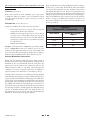
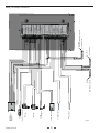
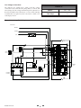
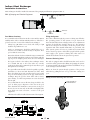
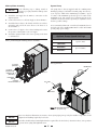
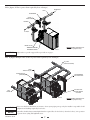
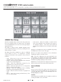
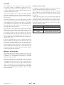
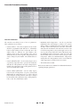
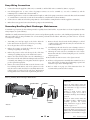
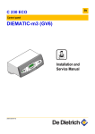
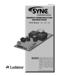
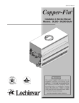
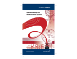
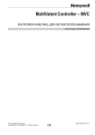
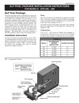
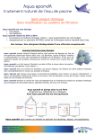
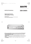
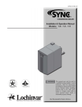
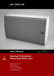
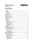
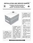
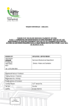
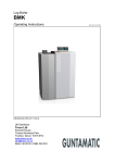
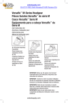
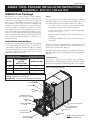
INS70111 Rev E AQUAS™ POOL PACKAGE INSTALLATION INSTRUCTIONS FOR MODELS: XPN 1015, 1320 and 1520 AQUAS Pool Package The AQUAS pool package system is a high efficiency commercial condensing boiler package system pre-piped to an indirect heat exchanger from the factory. This pool heater is a low temperature operating system designed to take advantage of the stainless steel heat exchanger and condensing operating temperatures to ensure the highest efficiency possible. The AQUAS is designed around a predetermined flow, set by the manufacturer, between the boiler and the indirect heat exchanger. The AQUAS operates off the pool system pump itself which will continually supply water to the indirect heat exchanger. This means there is no need to purchase a dedicated circulator to deliver water to this package system. Piping Pool / spa connections to the indirect heat exchanger are SCH 80 CPVC glue fittings. The connections from the field loop to the heat exchanger may be done in CPVC or PVC pipe as follows: • Use cement on the connections so they are rated for CPVC pipe and have enough body to hold the connection. • To make the connection, apply glue to both the CPVC flange and the section of pipe. • Insert the pipe into the flange until it reaches the bottom of the flange. • Turn the pipe a half turn in the socket to ensure that a proper seal is made. Installation Instructions To achieve the optimum operating efficiency of your AQUAS it is recommended that you keep the pool water flow of each appliance within plus or minus five gallons per minute of the recommended flow as stated in Table A. Low flow through the indirect heat exchanger will result in elevated temperatures supplied to the pool. TABLE A Pool water is designed to flow from right to left standing in front of the boiler. A factory installed sensor is on the inlet side of the indirect heat exchanger (FIG. 10, page 7). The supply and return water piping to the indirect heat exchanger shall be no smaller than 4" for Model 1015 and 6" for Models 1320 and 1520. Throttling Valve MODEL RECOMMENDED SYSTEM WATER FLOW CONNECTION SIZE 1015 243 4" 1320 316 6" 1520 364 6" A T of 8° - 10°F across the indirect heat exchanger is recommended. Throttling valves are used to set the flow through the indirect heat exchanger. (Standard gate valves are acceptable.) FIG. 1_Component Location RECOMMENDED CLEARANCES: BOILER - SEE SYNC I & O MANUAL INDIRECT HEX - ALLOW 18" FOR SERVICE ON ALL SIDES FLUE CONNECTION GAS INLET BOILER PUMP PRESSURE REDUCING VALVE / AUTO FILL VALVE EXPANSION TANK SYSTEM SENSOR LOCATION 1,000,000 - 1,500,000 BTU’S TEMPERATURE AND PRESSURE GAUGE RELIEF VALVE CUPRO-NICKEL POOL HEAT EXCHANGER SKID MOUNTED ON STEEL FRAME CONDENSATE DRAIN IMG00196 NOTE: Model 1520 shown for illustration purposes only. The system can be installed in either a Full Flow or Diverted Flow orientation: Apply a small amount of a high quality RTV silicone sealant to the threads to prevent leaks and install the limit and bulbwell into the threaded opening in the pipe. Install the limit control and bulbwell and tighten to seal. Do not over-tighten either part into the threaded opening in the PVC pipe. Over tightening can damage the parts and/or strip the threads cut into the plastic pipe. Wire the 110°F limit into the pool heater control circuit as shown in FIG. 2 on page 3. If additional wire length is needed, use 18 gauge wire for distances up to 30 feet. For longer distances, size the wire per Table B. Full Flow (reference FIG. 8) If the total system flow of the swimming pool or spa system is within five gallons per minute of the recommended system water flow as shown in Table A on page 1, this type of system is recommended. Diverted Flow (reference FIG.’s 9 & 10) TABLE B Remote Wire Connection Criteria for installing a diverted flow system is as follows: • If the total system flow is greater than the amount required by the indirect heat exchanger. • Installations with temperatures in excess of 95°F. This is necessary so the pool high limit will not trip. No water should enter the pool / spa in excess of 110°F. If the heat exchanger pool outlet is in excess of 110°F the water must be tempered down. • Multiple unit installation. Example: Total system flow is 1000 gallons per minute (GPM). If two 1,500,000 Btu/hr units were installed, each of the pool packages would require 364 GPM for a total of 728 GPM of the pool water being diverted through the indirect heat exchangers, while the other 272 GPM would be diverted back to the pool. Auxiliary Mixed Water Limit Control Ensure that the auxiliary 110°F mixed water limit control is installed in the filter system piping. Install the auxiliary limit a minimum of three feet downstream from the point where the heated water from the indirect heat exchanger is added to the filtration system (see FIG.’s 8 - 10). If the water leaving the heat exchanger is in excess of 110°F a bypass must be installed to temper the water below 110°F before re-entering the pool/spa. The limit will be mounted in a 3/8" NPT tapped fitting installed in the filtration system piping or it may be installed directly into a tapped opening in the PVC filter system piping. Turn off the filter system pump when installing the auxiliary limit in the filtration system piping. Tapped openings can be added to the PVC pipe by first drilling 9/16" pilot holes in the PVC pipe at least three feet downstream of the point where the heated water from the indirect heat exchanger is added to the filter piping. The drilled pilot holes can now be carefully threaded with a 3/8" NPT tap. After the pipe threads have been cut into the PVC pipe wall the limit and bulbwell can be inserted into the tapped openings. INS70111 Rev E 2 WIRE GAUGE MAXIMUM ALLOWABLE LENGTH 12 GA 100 ft. 14 GA 75 ft. 16 GA 50 ft. 18 GA 30 ft. INS70111 Rev E 3 TANK SENSOR SYSTEM SENSOR IMG00232 FROM PREVIOUS BOILER SHIELD A B B A SHIELD A B 3 RUN TIME LBL20052 REV B ENABLE 0 - 10V INPUT 30 SHIELD GND 29 A 28 B 26 SENSOR 27 SHIELD GND 25 TANK 23 OUT DOOR 24 SENSOR 21 SYSTEM 22 SENSOR 19 (+) 20 (-) 17 B 18 SHIELD GND 16 A 15 SHIELD GND 14 W 13 R 12 THERMOSTAT 10 FLOW SWITCH 11 TANK 9 MODULE 1 8 FLOW SWITCH 7 MODULE 2 6 PROVING 5 LOUVER 4 CONTACTS SHIELD MODBUS COMMUNICATION BUS TO NEXT BOILER TO NEXT BOILER SHIELD A B 1 ALARM 2 CONTACTS MOD BUS ENABLING DEVICE TANK THERMOSTAT MODULE 1 MODULE 2 110v HIGH LIMIT SENSOR BUILDING MANAGEMENT SYSTEM FIG.2_Low Voltage Connections CASCADE Line Voltage Connections TABLE C The AQUAS pool package has a single point line voltage connection for the boiler and the pump (FIG. 3). Connect 120 VAC wiring to the line voltage terminal strip in the junction box. Provide and install a fused disconnect or service switch (20 amp recommended) as required by local codes. Refer to Table C for total amps by model. Models 1015 - 1520 Total Amps 14.3 Figure 3 Line Voltage Field Wiring Connections 120V SUPPLY NEUTRAL W GROUND G LINE BK B SERVICE SWITCH W G DHW2/ SPA 2 W L G DHW1/ SPA 1 L B BK B B BK 2 4 6 8 PUMP 1 BK W PUMP 2 0 1 W RLY20038 RLY20040 INS70111 Rev E 4 JUMPER BK Indirect Heat Exchanger Installation Instructions Heat exchangers should be installed downstream of the pumping and filtration equipment (FIG. 4). FIG. 4_Pumping and Filtration Equipment TO POOL CHLORINATOR (DOWNSTREAM) TOP VIEW FROM POOL SYSTEM PUMP FILTRATION IMG00197 Pool Water Chemistry Filling the System It is essential that the instructions in this section and the Ryznar Stability Index and/or Calcium Stability Index are followed to prevent corrosion / erosion of the indirect heat exchanger: The boiler is filled through the pressure reducing auto-fill valve. The operating pressure of this system is 15 psi between the heater and the indirect heat exchanger. There are no adjustments necessary for the fill valve cartridge (factory set). The expansion tank is set at 20 psi. It is necessary to check the pressure of the expansion tank when annual maintenance is performed. The boiler system operates off a city or potable water system which feeds a closed loop system. A hard line is piped from the potable water supply to the pressure reducing valve. This water is to remain ON at all times when the system is in operation. - Always keep pH within correct levels. The ideal pool pH should be kept within 7.4 to 7.6. - Under no circumstances should the pH fall below 7.2 or rise above 7.8 (see FIG. 5). Check on a day-to-day basis. Alter pool conditions as necessary. - Ensure that chlorine levels are within the range recommended by the chemical manufacturer and are in accordance with the type of pool, for example; private, hotel, school or municipal. Pressure Reducing Valve - If a bypass is fitted to the indirect heat exchanger circuit, it is essential that any or all of the valves are correctly positioned to allow the recommended pool water flow to pass through the heat exchanger. The valve is equipped with a fast-fill feature that can be used to override normal operation when filling and purging the system. To activate fast-fill, push and hold down the fast-fill knob on top of the cartridge as shown in FIG.6. - The system filter unit should be checked regularly, especially sand filters (to detect sand and diatomaceous earth). Sand filters, if working incorrectly, can allow sand to pass around the pool circuit causing erosion of the pipe work and heat exchanger. Keep the pool free from debris such as leaves, grass cuttings, etc. This foreign matter can cause decay and increase pH. Relieve air from the system through operation of the pressure relief valve by pulling the lever on top of the valve, causing it to open. - It is essential that the correct chlorine dosage is added to the pool. To allow proper dispersion of the dose in the pool water, distribute the chemicals to various areas of the pool. Do not dose in one area only, as this will create highly acidic areas which can cause corrosion / erosion of the pool equipment. - Chlorinator should be installed downstream of the AQUAS. FIG.6_Pressure Reducing Auto-Fill Valve PUSH CAP DOWN TO ACTIVATE FAST FILL FIG.5_pH Scale 7.4 - 7.6 INS70111 Rev E 5 Makeup Water Assembly NOTICE System Pump In the following steps, a backup wrench is necessary to properly attach the makeup water assembly. 1. Attach the 3/4" nipple the the NPT tee connection on the AQUAS system. 2. Connect the brass tee to the brass nipple as shown in FIG. 7. 3. Attach the brass reducer to the female end of the street elbow. Attach the male end of the street elbow to the brass tee as shown in FIG. 7. 4. Connect the 1/2" nipple to the reducer bushing and connect the pressure reducing valve to the 1/2" nipple. 5. Attach the expansion tank to the center opening on the brass tee as illustrated. The pump that is factory-supplied with the Auxiliary Heat Exchanger package is a Grundfos VersaFlo pump. It is factoryset at “Speed 3” which is the maximum speed (100%). “Speed 2” is 80% of the maximum speed and “Speed 1” is 60% of the maximum speed. The current speed selections appear in the terminal box window and the speed may be adjusted between the three possible settings. It is recommended that a 30° - 35° Delta T be maintained across the boiler side of the Auxiliary HEX. Refer to Table D for HEX specific pump speed settings. TABLE D Optimal Pump Speed Settings HEX30058 FIG.7_Connecting the Makeup Water Assembly Speed 2 (80%) HEX30059 HEX30060 Speed 3 (100%) HEX30061 FIG.8_Full Flow 3/4” NIPPLE (BRS20031) FROM POOL 1/2” NIPPLE (BRS20022) CPVC IMG00728 STRAIGHT TEE (BRS20056) EXPANSION TANK AUXILIARY HEAT EXCHANGER 110 LIMIT TO POOL NOTE: Model 1520 shown for illustration purposes only. IMG00198 NOTICE Please note that these illustrations are meant to show system piping concept only, the installer is responsible for all equipment and detailing required by local codes. NOTICE System flow should always remain higher than the required flow for the boiler(s) when the boiler(s) is in operation to prevent short cycling and high limit issues. INS70111 Rev E 6 FIG.9_Bypass (if flow is greater than required by heat exchanger) FROM POOL CPVC FLOWMETER VALVE THROTTLING 110 LIMIT TO POOL RELIEF VALVE TEMPERATURE AND PRESSURE GAUGE NOTICE IMG00199 NOTE: Model 1520 shown for illustration purposes only. Adjust valves to provide suggested flow per Table A on page 1. FIG. 10_Bypass Multiple Units (if flow is greater than required by heat exchanger) 110 LIMIT (FOR EACH BOILER) VALVE THROTTLING (3X) FLOWMETER (3X) (OPTIONAL) RECOMMENDED ISOLATION VALVE FACTORY POOL RETURN SENSOR LOCATION CPVC PIPING IMG00200 NOTE: Model 1520 shown for illustration purposes only. NOTICE Please note that these illustrations are meant to show system piping concept only, the installer is responsible for all equipment and detailing required by local codes. NOTICE System flow should always remain higher than the required flow for the boiler(s) when the boiler(s) is in operation to prevent short cycling and high limit issues. INS70111 Rev E 7 SYNC control module Use the control panel (FIG. 11) to set temperatures, operating conditions, and monitor boiler operation. FIG. 11_Control Panel AQUAS Pool Setup • Service Mode - Allows the installer to control the fan speed of the individual control modules for the purposes of combustion analysis. Service Mode will override all automatic heat demands, however, all safeties will remain intact. When the ON/OFF switch is turned to the ON position, the first screen displayed will be the Status Screen. The Deatils Screen and Main Menu Screen can be accessed by pressing the appropriate button. The SYNC is equipped with a SMART TOUCH control system. All menu options are accessed by touching the screen with your finger or a stylus. Navigation to the Main Screen can be accomplished by pressing the MAIN button at the bottom of the page. The Main Screen allows navigation to eight (8) additional screens which are used to set temperatures, operating conditions, and monitor boiler operation. These screens are as follows: Reference the SYNC Service Manual for more information regarding the eight (8) accessible screens. Time - The time is displayed in the upper right-hand corner of the display. It is displayed in 24 hour format. Reference the night setback parameters in the SYNC Service Manual for information regarding adjusting the date and time. • Setup - Allows access to seven (7) other screens for the adjustment of the control parameters. • Cascade - Shows the status of multiple boilers connected together in a cascade arrangement. • Temps - Shows the temperatures measured by the individual sensors connected to the boiler. • Burners - Shows the status of the two (2) independent burner systems used in the boiler. • Building - Shows the information from a Building Integration System using Modbus Protocols. • Graphs - Allows the selection of items to be graphed on a chart. • History - Shows the operating and fault history of the two (2) control modules. Status button - Pressing this button displays the Status Screen. This screen shows the current status of the SYNC boiler. Access Modes User The user can view all of the settings on the LCD screen. By entering the user password #0704, the user can adjust User Set Point, HW Boiler Output Set Point, Backlight Time and Backlight Brightness Settings. Installer Most parameters are available only to the installer, accessible by entering the installer access code #5309. INS70111 Rev E 8 Cascade Sequence of the cascade When multiple boilers are installed, they can be wired together in a cascade sequence. A maximum of eight boilers can be controlled from a single control. In this application one boiler would be designated as the Leader control and all others would be designated as Member controls. To equalize the run time of all boilers on the Cascade, the firing sequence will automatically be changed at set intervals. For the first 24 hours after initializing the Cascade, the sequence will be changed every hour. After that the sequence will be changed once every 24 hours. The switching on/off sequence will be as follows: Once the Leader boiler receives a call for heat from the Enable input or 0 - 10 VDC input, the control will determine what the set point will be. A fixed temperature set point can be programmed into the control. If more than two boilers are on the Cascade, daisy chain the wiring from the Sequencing terminals on the second boiler to the Sequencing terminals on the third boiler, then from the third to the forth, and so on. The connections between boilers can be made in any order, regardless of the addresses of the boilers. Try to keep each cable as short as possible. If the water temperature at the system supply sensor is less than the set point + the turn-off offset - the off-on differential, then the control will initiate a call for heat on the Cascade (see the SYNC Service Manual for an explanation of the offset and differential). The Leader will energize the lead boiler on the Cascade. For a new startup this will be the Leader boiler. The boiler will fire at its ignition speed and will then modulate its firing rate to maintain the set point. If the first boiler reaches 100% of its firing rate, the Leader will calculate at what point the second boiler could fire at 10% of its firing rate. At this point, the Leader will fire the second boiler on the Cascade. For a new startup, this would be the first Member boiler. The boiler will fire at its ignition speed and will then modulate its firing rate to maintain the set point. If the set point still cannot be met, the Leader will continue firing more Members until either the heat demand is met or all boilers on the Cascade are firing. As the heat demand decreases, the last boiler on will modulate down to 10% of its firing rate. Once the demand for that boiler is zero, it will shut down. As the heat demand decreases further, the second to last boiler will modulate down and shut off. This will continue until the demand is satisfied and all boilers are shut off. Wiring of the Cascade When wiring the boilers for Cascade operation, select one boiler as the Leader boiler. The remaining boilers will be designated as Members. See “Configuration of the Cascade” for a detailed explanation of this procedure. Communication between the Leader boiler and the Member boilers is accomplished by using shielded, 2-wire twisted pair communication cable. Connect one of the twisted pair wires to terminal A on each of the Low Voltage Connection boards (FIG. 3), and the other wire of the twisted pair to terminal B on each of the Low Voltage Connection Boards. Connect the shield wires to one of the shield ground terminals on the Low Voltage Connection Boards. INS70111 Rev E 9 TIME SWITCHING ON SEQUENCE START L-M1-M2-M3-M4-M5-M6-M7 1 hour M2-M3-M4-M5-M6-M7-L-M1 2 hours M4-M5-M6-M7-L-M1-M2-M3 Cascade Parameters Screen: Cascade Parameters The Cascade Screen allows access to four (4) parameters. Those parameters are as follows: • Cascade Address - The boiler designated as the Leader should be programmed with address 0-1. All Member boilers require addresses from 2-3 through 14-15. The address must be different for each member. The addresses can be in any order, regardless of the order in which the boilers are wired together. This parameter can only be changed by the installer. The default address is 0-1. • Cascade Off Differential - Sets how many degrees above set point the temperature has to go before the lead boiler will shut off. This parameter can only be changed by the installer. The temperature range of this parameter is 0° to 72°F. The default value is 10°F. • Maximum Outlet Temperature - Sets the set point that individual boilers will attempt to achieve in a cascade. When a boiler is commanded to fire by the Leader, it will attempt to achieve this temperature at its outlet. The Leader will control the modulation of the last boiler to fire in order to hold the temperature at the system supply sensor to the user set point. If any of the boiler outlet temperatures reach the Maximum Outlet Temperature setting, the boiler will then modulate down on its own in order to keep its outlet temperature within the Maximum Outlet Temperature setting. Therefore, this parameter can be used to limit the outlet temperatures of all the boilers in a cascade. • The default value is 160°F. Reference the SYNC Service Manual for additional information regarding changing parameters. • Cascade Off/On Differential - Sets how many degrees below the turn off temperature (set point + Cascade Off Differential) the temperature has to go before the lead boiler will turn on. This parameter can only be changed by the installer. The temperature range of this parameter is 0° to 72°F. The default value is 20°F. INS70111 Rev E 10 Stand alone Operation Cascade Multiple Units Together Access the Set Up Screen from the Main Menu Screen, then select Setpoints. The following options will be available for Standalone Operation. Access the Set Up Screen from the Main Menu Screen, then select Setpoints. The following options will be available for Cascade. 1. User Set Point 1. User Set Point 2. Cascade OFF/ON differential 2. Cascade Address 3. Cascade OFF differential 3. Cascade OFF/ON differential 4. Maximum User Set Point 4. Cascade OFF differential To change parameters touch the hand icon on the screen and enter the installer code #5309. Proceed following the procedure below: 5. Maximum Outlet Temperature > Parameter Change > Set Point > Apply > Next > Set Up > Save Then proceed to the Boiler Status Screen. Sequence of operation Note: This unit is equipped with two (2) independent, but synchronized combustion systems. The Heat Exchanger 1 combustion system will fire first. If the demand cannot be met by one (1) combustion system the same sequence of operation will be followed to bring the Heat Exchanger 2 combustion system online. 1. Upon a call for heat, the control turns on the appropriate pumps (system and boiler pumps for a pool heating call, HW pump relay output for a HW call). 2. The control confirms that the low water cutoff and flow switch (optional) contacts are closed. 3. The control starts the blower and closes the louver contacts to begin the Pre-Purge cycle. 4. The control confirms that the blower comes up to the desired speed, the flap valve opens, and the air pressure switch, gas pressure switch (optional), louver proving switch (optional), and blocked drain switch contacts close. 5. Once the Pre-Purge cycle is complete, the control lowers the blower speed, initiates sparking of the ignition electrode, and opens the gas valve. 6. After a short wait, the control stops sparking and checks for the presence of flame current through the spark and flame sense electrodes. 7. If the control does not detect flame current, the control will lockout indefinitely, until the RESET button on the touch screen LCD is pressed. 8. If the control detects flame current, the control will hold the blower speed constant for a few seconds to allow the flame to stabilize, then begin modulating the firing rate in order to maintain the controlling sensor to the desired set point temperature. 9. If the current call for heat is for pool heating and an optional DHW call for heat becomes active, the control will turn on the HW pump relay output, then turn off the boiler pumps. It will then modulate the blower speed in order to maintain the outlet temperature to the desired DHW outlet set point temperature. 10. If the first heat exchanger in the boiler is unable to maintain the desired set point temperature, the second heat exchanger in the boiler will be started, using much of the same sequences as described above. Once both heat exchangers are firing, the controls will work in synchronization to maintain the desired set point temperature. If the heat load should decrease sufficiently, the second heat exchanger will be shut down, much like the sequences described below. 11. Once both the space heating and DHW calls for heat are satisified, the control will turn off the gas valve and begin the Post-Purge cycle. Any pumps that are running will begin their respective Pump Delay cycles. 12. At the end of the Post-Purge cycle, the louver contacts will open. 13. The control verifies that the blower stops running and the flap valve closes. 14. At the end of the Pump Delay cycle(s), the pump(s) will be turned off. INS70111 Rev E 11 Pump Wiring Connections 1. Connect the 120 volt supply line (white wire) to terminal (1) and the black wire to terminal (2) (FIG. 3, on page 4). 2. Cut field-supplied wire to create a three-leg jumper. Connect one end to terminal (2), one end to terminal (8) and the remaining end to terminal (10) as shown in FIG. 3. 3. Cut field-supplied wire to create two additional wire lengths to make boiler pump connections. Connect the first wire from terminal (7) to Boiler Hex 1. Connect the second wire from terminal (9) to Boiler Hex 2 as shown in FIG. 3. 4. Connect the two white wires from the pumps (FIG 3) to the neutral line coming from the 120 volt supply line, terminal (1). 5. Make all necessary ground connections from the pumps to the terminal strip. Secondary/Auxiliary Heat Exchanger Maintenance To maintain a pool system, the heat exchanger must be regularly cleaned and leak free. A system that is not cleaned regularly can have a major impact on system efficiency. Cleanliness is usually an internal (waterside) tube concern, and problems typically occur due to scale buildup and particulate deposits. This can result in loss of unit performance due to heat transfer problems and tube failure. Follow the procedure below to clean the secondary heat exchanger. 1. Turn OFF power and gas supply to the boiler. Allow the boiler and water in the system to cool before proceeding. 2. Close the gate valve to the heat exchanger. 7. Remove the tube sheet from the shell by sliding it to the left or right end of the shell. The sheet may be removed after one of the ends breaks free. 3. Relieve the pressure on both the boiler side of the heat exchanger by pulling the drain plug. 8. Visually inspect the tube sheet for wear or damage. A size 3 or size 4 cleaning brush is required to clean the heat exchanger. 4. Relieve the pressure on the tube sheet/pool side of the heat exchanger by pulling the plug on the naval brass bonnets. 9. Submerge the entire tube sheet vertically in a tub of water. Ensure that each tube is cleaned using this process, even if no clogs are present. 5. Remove the nuts and bolts that secure the CPVC flange to the bonnets on both ends of the heat exchangers and set aside for reassembly. Any damaged or torn gasket should be replaced per the replacement parts list. 6. Remove the socket head bolts that secure the bonnets to the heat exchanger shell. Remove each end to gain access to the tube sheet and set aside the bolts for reassembly. Remove the rubber O-ring on each end of the tube sheet. Replacement O-ring gaskets can be found on the replacement part sheet. 10. Reassemble the unit in reverse order of part removal. 11. If there is a bolt pattern in reassembly that contains four (4) or more bolts, follow a bolting pattern tightening sequence and follow the torque factor when tightening. 12. Refer to Table A on page one of this instruction sheet for recommended system water flow settings. FIG.12_Auxiliary Heat Exchanger Maintenance TUBE SHEET Revision Notes: Revision A (ECO C09876) initial release. BONNET FLANGE Revision B (ECO C10839) reflects the addition of the “Line Voltage Connection” section and Table C on page 2 as well as FIG. 3 on page 4. Revision C (ECO C11197) reflects the addition of pages 13-16 as well as information and images about DHW/Spa operation. SHELL O-RING FLANGE GASKET IMG00784 Revision D (ECO C12067) reflects the the addition of FIG. 7, “Makeup Water Assembly” procedure and “System Pump” information on page 6, and the removal of pages 13 - 16. (ECO C13276) reflects the inclusion of PVC piping in the “Piping” section on page 1, the addition of the “Secondary Heat Exchanger Maintenance” section and FIG. 12 on page 12 INS70111 Rev E 12 07/13 - Printed in U.S.A.