1
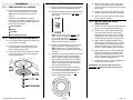
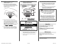
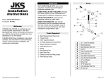
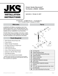
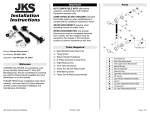
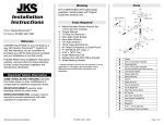
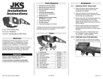
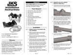
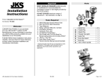
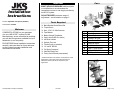
Important Installation Instructions MOST VEHICLES REQUIRE additional parts or modifications to accommodate the immediate increase in ride height provided by the ACOS system. DO NOT EXCEED maximum range of adjustment – see illustration on page 3. Product: Adjustable Coil Spacer (ACOS™) Part Number: PN 2550 Welcome CONGRATULATIONS on your purchase of a new JKS ACOS™ system! At JKS Manufacturing, we are committed to providing you with the best products available and your satisfaction is our first priority. PLEASE READ these Installation Instructions carefully, and save them for future reference, as they contain important installation and maintenance information. Parts Tools Required Metric/Standard Socket Wrench Set Torque Wrench 8mm, 1/4" & 5/16” Allen Wrenches Tape Measure Medium Strength Threadlocker Spray Lubricant (WD-40 or similar) Anti-Seize Lubricant Hydraulic Floor Jack Transfer Punch (or equivalent) 1/4” and 3/8” Drill Bits Coil Spring Compressor * Satin Black Spray Paint * Factory Service Manual (recommended) DESCRIPTION A B C D E F G H I Transfer Ring Adjuster Ring Threaded Tube (gold) Isolator Pad Bump Stop Support Bump Stop 10mm x 110mm Cap Bolt 5/16” x 1-3/8” Cap Bolts 5/16” Nylock Nuts QTY 2 2 2 2 2 2 2 6 6 * Asterisk denotes tools that are not required for some applications. Thoroughly read instructions first to determine which tools will be required for your application. PN 2200 (front application) pictured JKS Adjustable Coil Spacer Installation PN 2550 Page 1 of 3 Installation 1. REMOVE REAR COIL SPRINGS Remove the rear coil springs per the factory service manual instructions for your vehicle. HINT: A coil spring compressor is useful for removal. 3. DRILL UPPER SPRING MOUNT Remove the Adjuster Ring (B) and new Isolator Pad (D) from the pre-assembled ACOS unit. Rotate the Transfer Ring (A) on Threaded Tube (C) until top of Transfer Ring is just below top edge of tube. Locate and remove the bolt that secures the bump stop holder to the upper spring mount. Remove the bump stop holder. Remove the rubber isolator pad from the upper spring mount. Also remove any dirt or debris from the spring mount. Paint any exposed metal on the upper spring Position the Transfer Ring (A) against the upper spring mount and align the mounting holes. Insert a 5/16” x 1-3/8” Cap Bolt (H) through z Track Bar from the bump stop holder. location. Enlarge each hole with a 3/8” drill bit. SPRING MOUNT z Swaybar Pry the rubber bump stop (jounce bumper) free Using a 1/4” bit, drill a pilot hole at each hole 4. INSTALL ACOS ON UPPER z Shock Absorber 2. PREPARE UPPER SPRING MOUNT mount using a transfer punch or equivalent. Remove the ACOS components from the upper spring mount. mount to prevent corrosion. Depending on the application, it may be necessary to completely or partially remove any of the following components before spring can be free from upper mount. z Lower Suspension Arm Mark the hole locations on the upper spring HINT: Threaded Tube (C) is tapered on one end to fit properly against the upper spring mount. Other end of tube is recessed to accommodate the Bump Stop Support (E). Make sure tube orientation is correct! Position the Threaded Tube (C) with Transfer Ring (A) against the upper spring mount. HINT: Tapered end of Threaded Tube must contact spring mount to ensure Transfer Ring is centered. Temporarily secure the Threaded Tube (C) with Transfer Ring (A) in place by inserting the 10mm x 110mm Cap Bolt (G) through Bump Stop (F), Bump Stop Support (E), Threaded Tube (C), and then threading into the hole in center of upper spring mount. Bolt should be snug, but do NOT tighten yet. Rotate the Transfer Ring (A) on Threaded each hole and secure with a 5/16” Nylock Nut (I) from above the spring mount. Tighten bolts until snug, then loosen 1/2 turn so that Transfer Ring (A) is slightly movable by hand. Apply medium strength threadlocker to the upper threads of Threaded Tube (C). Thread tube completely into Transfer Ring (A) until it contacts the upper spring mount. This will center the Transfer Ring on the spring mount. Next insert the 10mm x 110mm Cap Bolt (G) through the Bump Stop (F) and Bump Stop Support (E), and thread into the hole in the center of the upper spring mount. Bolt should be snug, but NOT fully tightened yet. Now tighten the 5/16” x 1-3/8” Cap Bolts (H) to 40 ft-lb. using a torque wrench. IMPORTANT: The Transfer Ring (A) must rest completely flat against the upper spring mount. Tube (C) until the pre-drilled holes are in the 2-, 6-, and 10-o’clock positions, with the 6-o’clock hole located towards the rear of vehicle. See illustration below. JKS Adjustable Coil Spacer Installation PN 2550 Page 2 of 3 4. INSTALL ACOS ON UPPER SPRING MOUNT (cont.) Remove the10mm x 110mm Cap Bolt (G), Bump Stop (F), and Bump Stop Support (E) from upper spring mount and re-install Adjuster Ring (B) and Isolator Pad (D) onto the Threaded Tube (C). 5. SET ADJUSTER RING FOR DESIRED RIDE HEIGHT Once the Adjustable Coil Spacer is installed, rear ride height is determined by measuring the distance between top of Transfer Ring (A) and bottom of Isolator Pad (D), and subtracting 1/4” (0.25 in.). 6. RE-INSTALL REAR COIL SPRINGS Re-install the rear coil springs per the factory service manual instructions for your vehicle. HINT: A coil spring compressor is useful for installation. Also re-install any of the components that were removed during the REMOVE REAR COIL SPRINGS step of this installation. ATTENTION INSTALLER IMPORTANT NOTE REGARDING SHOCK ABSORBERS Most vehicles will require additional parts or modifications to accommodate the increase in ride height provided by the ACOS system. X” – 1/4” = RIDE HEIGHT * Apply anti-seize lubricant to the 10mm x 110mm Cap Bolt (G) and insert through Bump Stop (F) and Bump Stop Support (E). Thread bolt completely into hole in the center of upper spring mount, but do NOT tighten. HINT: Raised surface of Bump Stop Support (E) must face up and fully engage the recessed bottom of Threaded Tube (C). Slowly tighten 10mm x 110mm Cap Bolt (G) into the coil spring mount until sides of Bump Stop (F) begin to bulge. Do NOT overtighten! * Represents increase in ride height over OE suspension To prevent the coil springs from becoming unseated during maximum suspension extension, correct length shock absorbers must be installed. WARNING DO NOT EXCEED MAXIMUM RANGE OF ADJUSTMENT ADJUSTMENT RANGE * MINIMUM: 2” (2.0 in.) MAXIMUM: 3-3/8” (3.375 in.) Apply spray lubricant to Threaded Tube (C) and rotate Adjuster Ring (B) to desired position. Tighten recessed bolt in Adjuster Ring (B) to lock in position. Operation Future ride height adjustments should be made with NO LOAD on the rear coil springs, and the suspension at FULL DROOP. NEVER turn Adjuster Ring (B) while under tension, and ALWAYS apply spray lubricant to Threaded Tube (C) before adjusting. Maintenance Regular cleaning with pressurized water is recommended to maximize ease of operation and reliability. © 2009 JKS Manufacturing, Inc & Aftermarketing, LLC Revision Date 7/24/2009 JKS Adjustable Coil Spacer Installation PN 2550 Page 3 of 3