1
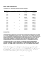
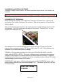
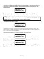
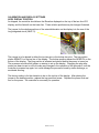
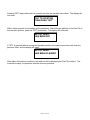
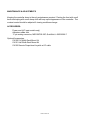
Installation
and Service
Manual
QuickTrac Series
Pan and Tilt
Controllers
International, Inc.
3650 Woodhead Drive * Northbrook, IL 60062-1895 U.S.A
Tel: 800 247-6563 * 847 498-0700 * Fax: 847 498-1258
www.quickset.com * email: [email protected]
© QuickSet International, Inc.
10/8/2001
MN00057
TABLE OF CONTENTS
Page
1.0
2.0
3.0
4.0
5.0
6.0
MODEL IDENTIFICATION CHART
1.1
Description
1.2
Identification of Controls
INSTALLATION
CALIBRATION AND DISPLAY SETTINGS
3.1
Calibration of the Display
3.2
Display Contrast
3.3
AZ/EL Readout Position
3.4
Zeroing the Readout to a Known Position
OPERATION
4.1
AUTOSCAN Function (Models With Meters Only)
MAINTENANCE & ADJUSTMENTS
ACCESSORIES
3
3
4
5
6
6
8
9
10
12
12
14
14
WARNING!
Carefully read all controller and Pan/Tilt documents BEFORE attempting to
connect and operate the Pan/Tilt control system. Improper connection between
the controller and Pan/Tilt may cause severe damage to either unit and void the
manufacturer's warranty.
If the user is unsure of the proper connections from the controller to the Pan/Tilt,
contact QuickSet International IMMEDIATELY for customer support.
Telephone:
1-800-247-6569
1-847-498-0700
Fax:
1-847-498-1258
Email:
[email protected]
Page 2 of 14
MODEL IDENTIFICATION CHART
This manual is for the following QuickSet QuickTrac controllers:
Model Number
C102
w/o meters
C437
12VDC
0-12VDC
24VDC
0-24VDC
24VDC
0-24VDC
115VAC
0-12VDC
115VAC
0-12VDC
115VAC
0-24VDC
115VAC
0-24VDC
230VAC
0-12VDC
230VAC
0-12VDC
230VAC
0-24VDC
230VAC
0-24VDC
x
x
x
x
x
C427
C432
0-12VDC
x
C337
C422
12VDC
x
C327
C332
Output Voltage
x
C207
C322
Input Voltage
x
C107
C202
w/meters
x
x
x
DESCRIPTION
The QuickSet QuickTrac Pan/Tilt Proportional Speed Controllers are used to control low voltage
DC Pan/Tilts using permanent magnet motors. These controllers are completely self contained
in a "3U" high, half rack, clear anodized enclosure with a black front panel. The controller is well
suited to surveillance and tracking applications as the joystick gives smooth control over a full
range of speed and direction. The controller may be used on a table or desk top with the
furnished rubber feet, or with the optional accessory rack kit, in a standard equipment rack.
Connection to the Pan/Tilt is with a circular 17 pin MS-style connector furnished with the
controller. Power to AC models is supplied with a 10' power cord plugged into the rear of the
enclosure. DC models include a “pigtail” with +VDC (red), -VDC (black) and ground (green)
wires.
Models with metering provide a backlit digital azimuth and elevation readout, showing the
operator the position of the pan and tilt when used with QuickSet Pan/Tilts equipped with
potentiometers. These models also include an azimuth “AUTOSCAN” function. Travel limits of
the AUTOSCAN are set electronically from the front panel of the controller. The indicated
“zero” position of the Pan/Tilt may also be reset by the user (see page 10).
Page 3 of 14
IDENTIFICATION OF CONTROLS
The illuminated power switch is also the protection circuit breaker. In event of an overcurrent
condition, determine and correct the cause, and press the rocker switch back to the ON position.
The front panel mounted joystick provides proportional speed and direction control to the
Pan/Tilt .
Positioning of the Pan/Tilt can be accomplished up to 15 feet away from the controller using the
optional CA102 remote joystick plugged into the controller.
Models “with meters” include a digital Elevation and Azimuth readout, a three position switch
and scan rate control for the “Autoscan” feature, and a “Set” button for setting the autoscan
limits and re-zeroing the metering.
The back panel includes a power inlet (AC input models) or wire pigtail (DC input models) and a
17 pin MS-style connector for direct connection to the Pan/Tilt.
Page 4 of 14
INSTALLATION
INPUT CONNECTIONS:
Installation of the controller involves providing input power by connecting it into a 115 or 230
VAC outlet (AC models), or applying DC current to the red (+) and black (-) pigtail leads (DC
models.)
OUTPUT CONNECTIONS: If the product was purchased with a cable from QuickSet, connect it
between the Pan/Tilt and the controller. Make sure the connectors are secured before
operating.
If you are constructing your own cable, wire the connector according to the information below:
MS3102E20-29S
CONTROLLER
PIN FUNCTION
A N/C
B Pot Reference “B”
C N/C
D Pot Reference “A”
E Left
F
Tilt position sense
G Ground
H N/C
J
Up
K Down
L
Right
M N/C
N N/C
P N/C
R N/C
S N/C
T
Pan position sense
SIGNAL LEVEL
May be used to supply power to heater
0 VDC
May be used to supply power to heater
+2.5 VDC
(-12 or -24) VDC to (+12 or +24) VDC
0 to +2.5 VDC
Earthen ground
(-12 or -24) VDC to (+12 or +24) VDC
(-12 or -24) VDC to (+12 or +24) VDC
(-12 or -24) VDC to (+12 or +24) VDC
0 to +2.5 VDC
Page 5 of 14
PAN/TILT
PIN
A
B
C
D
E
F
G
H
J
K
L
M
N
P
R
S
T
CALIBRATION AND DISPLAY SETTINGS
Calibration, display contrast, and AZ / EL readout positions require access to the inside of the
controller.
CAUTION---115 VOLTS AC AND HEAVY CURRENTS PRESENT INSIDE THE ENCLOSURE
CALIBRATION OF THE DISPLAY
Before opening the controller, turn of the power, and remove the power cord. Remove the
small screw in the middle of the rear of the top panel. Slide the top panel out of the enclosure,
and put it aside.
The controls for these functions are on the readout processor board located on the front of the
left side panel. The "CAL" switch is at the top/front of this board. The word "CAL" is on the
Printed Circuit Board next to it.
The calibration of the controller with the Pan/Tilt requires the user to monitor the Pan/Tilt
position using a method to measure 180° of pan rotation, and 90° of tilt. Once calibrated, the
calibration is non-volatile and should not change.
Calibration is required when changing from one model of QuickSet pan and tilt to another
model, such as QPT90 to QPT20. This is due to different amount of potentiometer resistance
changes for each degree of movement between the different pan and tilt models. Calibration
also determines the “direction” of indicated movement, increasing numbers indicate CW rotation
and decreasing numbers indicate CCW rotation.
PROCEDURE: Apply power. With the enclosure open, and the "AUTOSCAN" switch in the
center position, press the push button switch labeled "CAL". The display, at this time, will read
for three seconds:
PUSH "CAL" AGAIN
TO BEGIN
Page 6 of 14
During this interval, the push button will have to be pressed again. If this does not happen, the
read-out will return to normal operation. After the second activation of the push button, the
display will read:
PAN AZ TO "0°"
THEN PUSH "CAL"
Pan the azimuth to the zero or reference position with the joystick. Press the "CAL" switch to
set the chosen position as the reference.
NOTE: If you wish to change the “Zero” position later to a different reference position, you may
do so after this procedure by following the instructions listed “ZEROING THE READOUT TO A
KNOWN POSITION”. This may be done for Azimuth and/or Elevation.
The display will then change to read:
PAN AZ TO"+180°"
THEN PUSH "CAL"
The azimuth is driven 180° in either direction, and is set by pressing the "CAL" switch. This
allows software correction for changes in the zero reference location, and positive direction for
CCW or CW rotation with this calibration.
After the azimuth calibration is complete, the display will change to read:
TILT EL TO "0°"
THEN PUSH "CAL"
The tilt is driven to the zero or reference position and set by pressing the "CAL" switch. The
display will then read:
TILT EL TO "+90°"
THEN PUSH "CAL"
Tilt the elevation to 90° in either direction, and the position is set by pressing the "CAL" switch.
Again, “Zero” may be reset after this procedure. Up or down rotation can be set as positive
direction with this calibration.
Page 7 of 14
Calibration is now complete, and the display will read:
CAL COMPLETE
for three seconds, before returning to normal display indicating azimuth and elevation positions.
To interrupt the calibration procedure, for any reason, and not change the stored calibration,
wait for the processor to time out (approximately two to three minutes) during any step before
completing the entire calibration procedure. After that time, the display will go back to indicating
azimuth and elevation position. All steps in the calibration function must be completed before
the new calibration data is stored and used.
CALIBRATION AND DISPLAY SETTINGS
DISPLAY CONTRAST
The contrast potentiometer is at the bottom/front of this same board and, has the word "CONT"
adjacent to it.
CAUTION---115 VOLTS AC AND HEAVY CURRENTS PRESENT INSIDE THE ENCLOSURE
The contrast control has been set for optimum viewing in moderate light conditions, and
normally will not require any adjustments. It may be adjusted with a small plastic alignment tool
to prevent accidental shorting. It has a small range of adjustment. Full CW will make the
display very dark, and going CCW will make the display disappear. It should be adjusted for the
users best viewing condition.
Page 8 of 14
CALIBRATION AND DISPLAY SETTINGS
AZ/EL DISPLAY POSITION
As shipped, the controller should have the Elevation displayed on the top of the two-line LCD
display, and the Azimuth on the lower line. These relative positions may be changed if desired.
The jumper for the relative positions of the azimuth/elevation on the display is to the rear of the
long integrated circuit (68HC11).
The jumper is to be placed in either the top two pins or the bottom two pins. The top position
places AZIMUTH on the top line of the display. The bottom position places the AZIMUTH on the
bottom of the display. The plug position is selected and placed before the power is turned on.
The processor monitors this jumper on startup to set up the display. Changing the plug after
power has been turned on will not make any changes in the operation of the processor, until the
controller is powered up again, but could damage the processor board by static discharge, or
accidental shorting.
The factory setting is for the elevation to be on the top line of the display. After placing the
jumper in the desired position, replace the top panel and screw. Replace the power cord and
turn on the power. The controller is now ready for operation
Page 9 of 14
CALIBRATION AND DISPLAY SETTINGS
ZEROING THE READOUT TO A KNOWN POSITION
The procedure to move the zero reference of the Pan/Tilt without having to recalibrate the
controller, is as follows:
With the "AUTOSCAN" rocker in the center position ("OFF") press the "SET" pushbutton.
The display will at this time, read for five seconds:
PUSH "SET" AGAIN
TO CHANGE ZERO
By not pressing the second time in the time limit, the display will revert to the normal. Pressing
"SET" a second time within the five seconds will start the azimuth zero offset. The display will
now read:
PAN TO POSITION
THEN PUSH "SET"
Within three seconds the azimuth will be displayed.. After panning the Pan/Tilt to the new zero
position, press the "SET" pushbutton. The display will now read:
AZ-PAN ZERO
HAS BEEN SET
If the "SET" is pressed without moving the azimuth position, the read-out processor will clear
any previous offset, and the display will read:
AZ-PAN ZERO
HAS BEEN CLEARED
After either of the above conditions the following will be displayed:
PUSH "SET AGAIN
FOR EL-TILT ZERO
Page 10 of 14
Pressing "SET" again within the five seconds will start the elevation zero offset. The display will
now read:
TILT TO POSITION
THEN PUSH "SET"
With-in three seconds, the elevation will be displayed. After tilting the platform on the Pan/Tilt to
the new zero position, press the "SET" pushbutton. The display will now read:
EL-TILT ZERO
HAS BEEN SET
If "SET" is pressed without moving the elevation position, the read-out processor will clear any
previous offset, and the display will read:
EL-TILT ZERO
HAS BEEN CLEARED
After either of the above conditions, the read-out will be displaying the Pan/Tilt positions. The
controller is ready for operations with the new zero positions.
Page 11 of 14
OPERATION
To turn on the controller, press the top of the "POWER" circuit breaker. The LED in the center
of the circuit breaker rocker and the backlight of the display (Models with meters only) will
illuminate. In a few seconds the metered models will display azimuth and elevation positions.
To use the joystick in the controller, the jumper plug must be inserted into the "REMOTE"
joystick connector. When use of the optional remote joystick is desired, remove the jumper
plug, and install the remote joystick. The jumper plug is attached to the panel with a short ball
chain to keep it with the controller.
The joystick is used to move the Pan/Tilt in any direction and speed desired. To move the
Pan/Tilt in the left or counter-clock-wise (CCW) direction (as viewed from the top of the Pan/Tilt),
move the lever to the left. To move it in the right or clock-wise (CW) direction, move the lever to
the right. To move the elevation platform “down”, push the lever down, and for “up”, push the
lever up.
NOTE: The above is for the “normal” operation. The actual movement direction is dependent on
the calibration process. See “CALIBRATION OF THE DISPLAY” for additional information.
AUTOSCAN FUNCTION (MODELS WITH METERS ONLY)
The autoscan function has three controls:
1) A rocker switch with a center off position.
2) A small push button for setting limits.
3) A knob for setting the speed of the pan in autoscan.
For autoscan operation it is first necessary to set in the limits required for operation. To set up
the scan limits, the "AUTOSCAN" rocker switch is pressed to the left position labeled "LIMIT
SET". The display will read:
AUTOSCAN
SET LIMITS
After three seconds, the display will read:
PAN AZ TO -LIMIT
THEN PUSH "SET"
Page 12 of 14
After three seconds, either the top or bottom line will be replaced by the actual azimuth position.
In this example, the most negative pan position of the azimuth to be scanned is –27.2
Azimuth –27.2
Using the joystick, pan the Pan/Tilt to the most negative (lower) limit of the area to be scanned,
and push the “SET” button. The display will now read:
PUSH AZ TO +LIMIT
THEN PUSH "SET"
After three seconds the display will show the azimuth position as before. Pan the Pan/Tilt to the
most positive (upper) limit of the area to be scanned, and push the “SET” button.
After completion of the directed steps, the display will read:
RETURN ROCKER TO
CENTER POSITION
Return the rocker to its center position, "OFF". The display will now read for three seconds:
SCAN LIMITS SET
It will then return to the normal display.
The AUTOSCAN function is now ready. To run the AUTOSCAN, press the right side of the
"AUTOSCAN" rocker to "SCAN". An LED indicator will show when AUTOSCAN is running, and
the color in which direction. (RED CCW, GREEN CW) The Pan/Tilt will move into the selected
SCAN range from any starting position. The SCAN RATE knob adjusts the pan speed during
AUTOSCAN operation. To return to normal operation, move the rocker switch to the center
position.
Page 13 of 14
MAINTENANCE & ADJUSTMENTS
Keeping the controller clean is the only maintenance required. Dusting the front with a soft
brush and wiping with a soft damp cloth will keep up the appearance of the controller. The
contrast control should be adjusted if viewing conditions change.
ACCESSORIES:
Power cord (AC input models only)
Adhesive rubber feet
17-pin mating connector, MS3106F20-29P, QuickSet # 490126286-7
Optional Accessories:
CA100 Full Width Rack Mount Kit
CA101 Half Width Rack Mount Kit
CA102 Remote Proportional Joystick w/15’ cable
Page 14 of 14