1
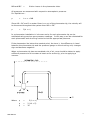
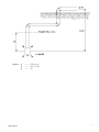
Twin Cylinder De-Airing Unit
User Manual
Man 165
3.0.1
06/08/2014
C.Spalton
Andy Small
Chris
Rasmussen
Manual No.
Revision
Date
Originator
Checked
Authorised for
Issue
User Manual
1
Contents
Section 1 :
Forward......................................................................................................... 3
Section 2 :
Introduction .................................................................................................. 4
Section 3 :
Installation Of The De-Airing Unit ................................................................. 5
Section 4 :
Preparation And Setting Up ........................................................................... 6
FIGURE 1 .......................................................................................................................... 6
Section 5 :
Operating And Recharging............................................................................. 8
Section 6 :
Calculation Of De-Airing Pressures For Piezometers ...................................... 9
Section 7 :
Calculating De-Airing Water Volumes .......................................................... 12
Section 8 :
The De-Aired Water Boiler ........................................................................... 13
FIGURE 2........................................................................................................................ 13
User Manual
2
Section 1 : Forward
It is essential that the equipment covered by this manual is both installed and
operated by competent and suitably qualified personnel. They must both READ AND
UNDERSTAND the procedures outlined in this manual before attempting installation
or operation of the equipment on site.
All systems are designed to operate consistently under normal field conditions but
although their components are relatively robust for such sensitivity they will not
survive mishandling or neglect. Treat all items with respect and handle with CARE.
Obviously these techniques can only serve as a general guide and will require
modification to suit particular circumstances on site. If difficulties are encountered
time will usually be saved by contacting Soil Instruments at the earliest opportunity.
User Manual
3
Section 2 :
Introduction
The de-airing unit consists essentially of a pressure and a supply tank and a gauge to
measure water pressure during circulation of de-aired water. All these components
are mounted on a frame or panel complete with valves and connecting pipework.
Pressure and vacuum pumps are used to operate the equipment. Pressure is applied
to the de-aired water in the supply tank by forcing water from the pressure tank into
the bladder in the supply tank. Water from the supply tank may then be circulated
through the tubes. The volume changes measured in the pressure tank indicates the
quantity of water circulated through the system.
The equipment has been fully tested to the operating pressure and vacuum before
despatch. However, it is possible that movements during transit may disturb the
cylinders, pipework or valves sufficiently to cause small leaks when the equipment is
operated. If any leaks are observed during operation they should be eliminated by
gently tightening the appropriate component.
NEVER modify the arrangement without the full written approval of Soil Instruments
as unauthorised modifications may bypass the safety system.
It is advisable to drain water from the equipment during cold weather to prevent
damage to the cylinders due to freezing.
WARNING
If an anti-freeze solution is used, the system must be flushed with clean water to
prevent the bladder from perishing over time.
WARNING
External high pressure gas cylinders must not be connected to this de-airing unit.
User Manual
4
Section 3 : Installation of the De-Airing Unit
The unit should be mounted vertically and level either on wooden battens fixed to the
instrument house wall, at a convenient height for the operation of all the valves, or
stood on a level working surface. The terminal panels should be connected to the
elbow connection on the valve marked C on the de-airing unit.
Under normal operating conditions the foot pressure pump is connected to the special
Schaeder connector on valve A and the foot vacuum pump is attached to valves B
and E, as appropriate.
WARNING
External high pressure gas cylinders must not be connected to this de-airing unit.
User Manual
5
Section 4 : Preparation and Setting Up
PRESSURE
GAUGE
K
E
G
PRESSURE
CYLINDER
J
H
SUPPLY
CYLINDER
P
L
WATER
SUPPLY
TO INSTRUMENT
MANIFOLD
VALVE 'S' ON
WATER BOILER
FIGURE 1
The valves must be operated in the order given, commencing with all the valves in
the closed position.
4.1. Attach the vacuum pump with the black hose supplied to valve B. Open valves
B, D and E and apply vacuum until the bladder in the supply cylinder is
completely evacuated. Close all valves.
4.2. Immerse the red rubber tube into a container of clean water to remove all the
air and then attach one end to valve C at the base of the pressure cylinder.
Open valves C and B and operate the vacuum pump drawing the water into the
pressure cylinder. When this tank is 90% full, close valves C and B. Remove
the vacuum hose from valve B, open valve B to release the vacuum, and then
close it again.
4.3. Attach the vacuum hose to valve E on the supply cylinder and open the valve.
Open valve B and D on the pressure cylinder. Slowly create a vacuum in the
supply cylinder using the vacuum pump, this will draw water into the bladder.
User Manual
6
When the pressure cylinder is almost empty, close valve D. Remove the vacuum
hose from valve E and then close valve E after the vacuum has equalised.
4.4. Connect the vacuum hose to valve B on the pressure cylinder. Attach one end
of the red rubber tube to valve S on the boiler and the other end to, valve F on
the supply cylinder. Open valves, B, D and F on the de-airing unit and valves S
and V on the boiler. (NEVER open valve S before opening valve V with a
partial vacuum inside the boiler, as this will draw air into the de-aired
water). Use the vacuum pump to draw the water into the cylinder from inside
the bladder in the supply cylinder. This draws water from the boiler into the
supply cylinder.
4.5. When the pressure cylinder is 90% full, close all valves. Connect the pressure
pump to the Schraeder valve (similar to a motorcar tyre inflation valve) above
valve A. Open valves A, D and E. Generate a little pressure using the foot
pump so that the water in the pressure cylinder is, again, forced into the
bladder in the supply cylinder.
TAKE CARE! As soon as water comes out of valve E close it and open valve B to
release the pressure. Close valve B.
4.6. To completely evacuate the bladder, open valves S and V on the boiler and
valves B, D and F on the de-airing unit. Using the vacuum pump, draw the
water from inside the bladder into the pressure cylinder, thereby filling the
supply cylinder outside the bladder. When the pressure cylinder is 95% full
close all valves
The unit is now full and ready for operation.
WARNING
If an anti-freeze solution is used, the system must be flushed with clean water to
prevent the bladder from perishing over time.
User Manual
7
Section 5 : Operating and Recharging
To purge hydraulic equipment of air, carry out the following steps, opening the
valves in the order given:5.1. Confirm the pressures to be used to flush the tubes with de-aired water and the
volumes required.
For overflow cells the pressures required will be very low, for piezometers or
settlement cells higher pressures may be required.
5.2. Start with all the valves in the closed position. Fit the foot pressure pump lead
to the Schaeder valve on valve A and open valves D, and G. Open/close the
appropriate valves on any terminal panel that may be installed.
5.3. Apply pressure gradually so that the level of water in the pressure cylinder
slowly begins to fall. Observe the volume changes on the pressure cylinder’s
graduated scale.
5.4. As water circulation proceeds the pressure will drop slowly and it will be
necessary from time to time to re-adjust it to the original calculated value by
operating the foot pump.
5.5. Circulate water until no more air bubbles are seen to be returning through the
water in the return lines. Finally check that the volume of water returning
corresponds to the volume leaving the de-airing unit. (Volume from pressure
cylinder).
5.6. When the flushing operation is complete or the level in the pressure cylinder is
almost at the base of the sight glass, close all valves. Open valve B to release
any pressure trapped in the pressure cylinder and then close it again.
5.7. During operation of the unit the bladder in the supply cylinder should not be
allowed to distend to more than 75% of the volume of the cylinder. At this
point it is necessary to recharge with de-aired water as follows:
5.8. Attach one end of the red rubber tube to valve S on the boiler and the other end
to valve F on the supply cylinder. Open valves V and S on the water boiler
(NEVER open valve S before opening valve V with a partial vacuum inside the
boiler, as this will draw air into the de-aired water) and valves B and D on the
pressure cylinder and valve F on the supply cylinder.
Using the vacuum pump draw the water from inside the bladder into the
pressure cylinder, thereby filling the supply cylinder outside the bladder with deaired water from the de-aired water boiler. When the pressure cylinder is 95%
full close all valves.
The unit is now full and ready for operation again.
User Manual
8
Section 6 : Calculation of De-Airing Pressures For Piezometers
It is important that pressures used to de-air piezometers are carefully controlled. If
too little pressure is applied the de-airing process will take a long time. If too much
pressure is applied there may be a risk of hydro fracturing the soil around the
piezometer tip.
The following calculations would be used to determine a balanced condition from
which the send pressure would be increased to generate a steady flow observed in
the tubing and in the pressure cylinder.
There are many factors that can affect the pressures required to generate a flow
and care must be taken not to exert too much pressure on the system without
knowing where this pressure is being exerted. Hydro fracture of a soil will create a
fissure in the material that could possibly form a drainage path.
When a piezometer and its tubing are to be filled with water for the first time, it is
very important to slowly and steadily fill the tubes with the minimum pressure
required to create a flow. This ensures that all the air in the tubes will be displaced
by the water.
When de-airing a “Low Air Entry” piezometer tip it may be necessary to initially
purge both tubes with water under pressure rather than expecting the water to be
sent down one and return down the other.
Once a steady flow has been achieved an appropriate volume of de-aired water
should be flushed through the tubes and the returned water should be checked for
air bubbles.
Consider a piezometer tip in the soil during the de-airing process as follows:u
p
h
User Manual
=
=
=
pore pressure in the fill at the tip.
pressure on the pressure side of the de-airing unit.
difference in head between the piezometer tip and the pressure
gauge on the de-airing
unit.
h
9
fAB and fBC
=
friction losses in the piezometer tube.
All pressures are measured with respect to atmospheric pressure.
For Equilibrium:p
=
h + u + fAB
Since AB = BC and if no water flows in or out of the piezometer tip, the velocity will
be the same throughout the system then fAB = fBC
p
=
2(h + u)
In a piezometer installation h is known and u for each piezometer tip can be
estimated using previous pore pressure readings. In this way p can be calculated for
each piezometer and de-airing carried out at the appropriate pressure.
If the piezometer lies below the readout point, the term h, the difference in head
between the piezometer tip and the pressure gauge on the de-airing unit, changes
sign and becomes negative.
When a piezometer tip has accumulated a lot of air, care should be taken to apply
sufficient pressure to drive water at least as far as the tip, prior to applying a
vacuum.
Where
User Manual
p
=
2 (h + u)
p
p
=
=
2 (10 + 5)
30
10
Where
User Manual
p
=
2 (h + u)
p
p
=
=
2 (-7 +4)
-6
11
Section 7 : Calculating De-Airing Water Volumes
After calculating de-airing pressures (see Sections 4 and 5) it is important to
determine the volume of de-airing water to be circulated through each instrument.
The amount of de-aired water required depends on the length of instrument tubing
between the installed instrument and the de-airing unit.
Under normal conditions we use tubing with 2.8mm internal diameter and 4.8mm
outer diameter (3/16”), 3.8mm internal diameter and 6.4mm outer diameter (1/4”)
or 5.4 mm internal diameter and 8.0mm outer diameter (5/16”).
The tubing can be installed as two separate tubes, each with a 1mm polythene
sheath or as two tubes within a single polythene sheath.
7.1. Determine which size of tubing has been installed by precisely measuring the
outer diameter.
7.2. Calculate from installation layout drawings or physically measure the distance
from the installed piezometer tip to the de-airing unit.
7.3. Multiply installed length ( in metres x 100 ) by the appropriate cross sectional
area in cm2 (0.062 for tubing with 2.8mm internal diameter, 0.11 for tubing
with 3.8mm internal diameter or 0. 23 for tubing with 5.4 mm internal diameter)
to give de-airing water volume in cubic centimetres ( cm3 ).
Add 500cc for the volume of the tip and at least 10% to the calculated volume to allow
for tube snaking etc.
User Manual
12
Section 8 : The De-Aired Water Boiler
Up to 50 litres of de-aired water can be prepared in the boiler at one filling. A heater
coil heats the water to boiling thus expelling any air or gases in solution. By sealing the
boiler and allowing it to cool, the steam and water vapour above the water condense
thus creating a partial vacuum inside the boiler. This prevents further solution of air or
gases.
8.1.
Open valves V and S. Remove the central filler-cap using the spanner provided.
8.2.
Fill with clean water to within 100mm of the top.
8.3.
Connect the electrical cable to a suitable mains supply (either 110V or 230V
as indicated on the heater coil cover). Switch on at the mains. Bring to the
boil and allow to boil for fifteen minutes. Switch off at the mains supply.
8.4.
Close valves V and S replace the central filler-cap. Allow to cool.
FIGURE 2
WARNING: Although the cap is fitted with a pressure relief valve, NEVER boil
with the filler-cap on.
With a partial vacuum inside the boiler, NEVER open valve S before opening
valve V, as this will draw air into the de-aired water.
NOTE :
SAFETY REQUIREMENTS: The 4 psi Pressure Relief Valve in the centre of the filler-cap
must be checked by a competent person, at intervals not exceeding 12 months.
Bell Lane, Uckfield, East Sussex
t: +44 (0) 1825 765044
e: [email protected]
TN22 1QL United Kingdom
f: +44 (0) 1825 744398
w: www.itmsoil.com
Soil Instruments Ltd. Registered in England. Number: 07960087. Registered Office: 5th Floor, 24 Old Bond Street, London, W1S 4AW
User Manual
13