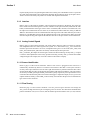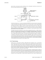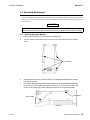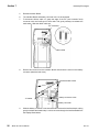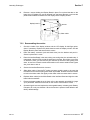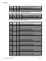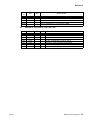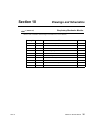
1
HAND-HELD RESPIRATORY MECHANICS MONITOR Service Manual Model 101 April 17, 2000 Catalog No. 6800-90-01 Novametrix Medical Systems Inc. PO Box 690 5 Technology Drive Wallingford, Connecticut, U.S.A. 06492 Revision History Revision History Rev. 01 22-May-98 Release 17-Apr-00 Revision 01, R-N746 Model 101 Service Manual iii Revision History [This page intentionally blank.] iv Model 101 Service Manual Rev. 01 Table of Contents Safety ..................................................................................................... 1 Introduction ........................................................................................... 3 Keypad Controls and Indicators ........................................................................ 4 Symbols ............................................................................................................. 4 Theory of Operation ............................................................................. 5 Main Board ........................................................................................................ 5 Power Supply ..............................................................................................................5 Reference Voltages .....................................................................................................5 Battery Charger ........................................................................................................... 5 On/Off Control ............................................................................................................. 6 Digital Control and Microprocessor ............................................................................. 6 Serial Communication .................................................................................................7 Audio ........................................................................................................................... 7 Interface ...................................................................................................................... 8 Analog Control Signals ................................................................................................8 Sensor Identification .................................................................................................... 8 Flow Zeroing ............................................................................................................... 8 Flow Circuitry ..............................................................................................................9 Barometric and Airway Pressure ...............................................................................10 Interface Board ................................................................................................ 11 Key panel Interface ...................................................................................................11 Display interface ........................................................................................................11 LED control ...............................................................................................................11 Power Supplies ......................................................................................................... 11 Functional Tests ................................................................................. 13 Equipment Required ........................................................................................ 13 Procedure ........................................................................................................ 13 Accuracy Tests ................................................................................... 15 Equipment Required ........................................................................................ 15 Procedure ........................................................................................................ 15 Electrical Tests ................................................................................... 17 Equipment Required ........................................................................................ 17 Rev. 01 Model 101 Service Manual v Table of Contents Procedure ........................................................................................................ 17 Power Supplies ......................................................................................................... 17 Airway Pressure Calibration ...................................................................................... 18 Differential Pressure Calibration ............................................................................... 19 Barometric Pressure Calibration ..................................................................... 19 Maintenance ........................................................................................ 21 General ........................................................................................................... 21 Maintenance Schedules .................................................................................. 21 Cleaning and Sterilization ................................................................................ 22 Battery and AC Operation ............................................................................... 22 Battery Installation .................................................................................................... 23 External Battery Charger .......................................................................................... 23 Features Connector .................................................................................................. 23 Assembly Exchanges ...................................................................................... 24 Disassembling the Monitor ........................................................................................ 24 Reassembling the monitor ........................................................................................ 26 Accessories ......................................................................................... 27 Parts Lists ............................................................................................ 29 6800-00 Final Assembly, Model 101 ......................................................................... 29 6800-01 Main Assembly, Model 101 ......................................................................... 29 2740-01 01 Main Board Assy, Model 101 ................................................................. 30 2740-17 01 Main Board Subassy, Model 101 ........................................................... 30 2739-01 00 Battery & Comm Interface Board Assy .................................................. 32 2741-01 00 Interface Board Assy, Model 101 ........................................................... 32 6935-48 00 Test Fixture, Flow Leak Test ................................................................. 33 Drawings and Schematics ................................................................. 35 vi Model 101 Service Manual Rev. 01 Guarantee Equipment manufactured or distributed by Novametrix Medical Systems Inc., is fully guaranteed, covering materials and workmanship, for a period of one year from the date of shipment, except for certain disposable products and products with stated guarantees other than one year. Novametrix reserves the right to perform guarantee service(s) at its factory, at an authorized repair station, or at the customer’s installation. Novametrix’ obligations under this guarantee are limited to repairs, or at Novametrix’ option, replacement of any defective parts of our equipment, except fuses, batteries, and calibration gasses, without charge, if said defects occur during normal service. Claims for damages during shipment must be filed promptly with the transportation company. All correspondence concerning the equipment must specify both the model name and number, and the serial number as it appears on the equipment. Improper use, mishandling, tampering with, or operation of the equipment without following specific operating instructions will void this guarantee and release Novametrix from any further guarantee obligations. Service Department For factory repair service, call toll free 1-800-243-3444 In Connecticut, call Collect (203) 265-7701 FAX (203) 284-0753 http://www.novametrix.com Email [email protected] Caution: Federal (U.S.A.) law restricts this device to sale, distribution, or use by or on the order of a licensed medical practitioner. Copyright 1998, 2000 Novametrix Medical Systems Inc. This document contains information which is proprietary and the property of Novametrix Medical Systems Inc., and may not be reproduced, stored in a retrieval system, translated, transcribed, or transmitted, in any form, or by any means, without prior explicit written permission from Novametrix Medical Systems Inc. Declaration of Conformity with European Union Directive The Authorized Representative for Novametrix equipment is: D.R.M. Green European Compliance Services Limited Oakdene House Oak Road Watchfield Swindon, Wilts SN6 8TD Rev. 01 Model 101 Service Manual vii Guarantee Service Policy Novametrix Medical Systems Inc. provides 24-hour a day access to technical support through its Technical Support Department in Wallingford, Connecticut, and company Service Representatives located throughout the United States. (Outside the U.S., primary technical support is handled through our qualified international sales and service distributors.) Novametrix will provide Warranty Service support within 48 hours of receiving a request for assistance. Contact the Technical Support Department by telephone toll free at 800-243-3444, or 203-265-7701; by facsimile at 203-284-0753; or, by e-mail at [email protected]. After hours telephone support requests (before 8:00 AM and after 5:00 PM Eastern Time) will be responded to promptly by the Technical Support on-call staff. After hours facsimile and e-mail requests will be answered the next business day. It is suggested that any person calling in for technical support have the equipment available for product identification and preliminary troubleshooting. Novametrix reserves the right to repair or replace any product found to be defective during the warranty period. Repair may be provided in the form of replacement exchange parts or accessories, on-site technical repair assistance or complete system exchanges. Repairs provided due to product abuse or misuse will be considered “non-warranty” and invoiced at the prevailing service rate. Replaced or exchanged materials are expected to be returned to Novametrix within 10 days in order to avoid (additional) charges. Return materials should be cleaned as necessary and sent directly to Novametrix using the return paperwork and shipping label(s) provided. (Transferring return materials to a local sales or dealer representatives does not absolve you of your return responsibility.) Novametrix manufactures equipment that is generally field serviceable. When repair parts are provided, the recipient can call Technical Support for parts replacement assistance and repair assurance. In the event a replacement part requires increased technical capability, Technical Support may request Biomedical assistance, provide on-site technical support or complete replacement equipment. If the customer requires the return of their original product, the exchange material will be considered “loaner material” and exchanged again after the customer equipment is repaired. Novametrix promotes customer participation in warranty repairs, should they become necessary. A longer useful product life, and quicker, more cost-effective maintenance and repair cycles—both during and after the warranty period, are benefits of a smooth transition into self-maintenance. The Technical Support Department can provide technical product support at a level appropriate to your protocol and budget requirements. Please contact Technical Support for information on these additional programs and services: • Focus Series Technical Training Seminars • Test Equipment and Test Kits • Service Contract / Parts Insurance Plans • On-Site Technical Support • “Demand Services” including Flat rate parts-exchange Flat rate return for repair Time and Material • Full warranty, discounted replacement sensors viii Model 101 Service Manual Rev. 01 Section 1 Safety The VENT✔ Handneld Respiratory Mechanics Monitor, Model 101, is electrically isolated. Patient leakage current flowing from the instrument to ground is limited to less than 10 uA. • Keep the VENT✔ and its accessories clean. Do not operate the VENT✔ when it is wet due to spills or condensation. • Connect only Novametrix Series 3 Flow Sensors to the VENT✔. For maximum performance; keep the pressure sensor ports oriented upward, and keep the sensor clear of moisture and secretions by proper breathing circuit maintenance. • Connect the sensor first to the VENT✔ and then to the patient breathing circuit in order to limit circuit volume loss and to avoid excessive moisture build-up in the flow sensor tubing. • VENT✔ has electrically isolated inputs. Patient leakage current flowing from the instrument to ground is limited to less than 10 µA at 120 V, 60 Hz. Patient isolation is greater than 10 MΩ, 2500V rms at 60 Hz. • Where electromagnetic devices (i.e., electrocautery) are used, patient monitoring may be interrupted due to electromagnetic interference. Electromagnetic fields up to 3 V/m will not adversely affect system performance. • VENT✔ contains no user serviceable parts. Refer servicing to qualified service personnel. • This product and its accessories which have patient contact are latex free. For maximum patient and operator safety, observe the following warnings and cautions. WARNINGS ! Rev. 01 Indicates a potentially harmful condition that can lead to personal injury. • Explosion Hazard: Do NOT use the VENT✔ in the presence of flammable anesthetics. Use of this instrument in such an environment may present an explosion hazard. • Electrical Shock Hazard: Always turn the monitor off before cleaning it. Do NOT use a damaged monitor or sensor. Refer servicing to qualified service personnel. • Fire Hazard: The VENT✔ should not be exposed to elevated oxygen levels at elevated pressures. Use in such an environment may present a fire hazard. • Failure of Operation: If the monitor fails to respond as described, do not use it until the situation has been corrected by qualified personnel. • Do not apply tension to the sensor tubing while connected to a patient breathing circuit, as accidental extubation may result. • Do not position the flow sensor’s tubing in any manner that may cause entanglement or strangulation. • Use the optional external battery charger in non-patient areas only. Model 101 Service Manual 1 Section 1 CAUTIONS Indicates a condition that may lead to equipment damage or malfunction. • Federal (U.S.A.) law restricts this device to sale, distribution, or use by or on the order of a licensed medical practitioner. • Electrical Shock Hazard: Always turn the monitor off before cleaning. Do NOT use a damaged monitor. • Do NOT use a damaged flow sensor. • Do NOT immerse the monitor or sensors in liquids. • Do NOT sterilize the monitor or the sensors. • No user serviceable parts inside. Refer servicing to qualified service personnel. • Operate at temperatures between +10° C to +40° C (50-104° F), < 90% relative humidity (noncondensing). • Avoid storing the monitor at temperatures less than -20° C or greater than +55° C (<-4° F or >131° F). NOTES Indicates points of particular interest or emphasis for more efficient or convenient operation. • The VENT✔ operates with Novametrix Series 3 Flow Sensors only. • The VENT✔ performs an automatic zero (self calibration) periodically and as needed. During this time, monitoring is interrupted for less than three seconds. • The automatic zero can be manually initiated by simultaneously pressing the DATA and GRAPH keys. After changing the sensor from Adult to Neonatal (while the VENT✔ is operational), wait 30 seconds then perform an automatic zero. • This product and its accessories which have patient contact are free of latex. • The C20/C Compliance Ratio (neonatal) parameter is not supported. • To determine the VENT✔ software version, turn the monitor on. During the self test performed at power up, the software level is shown on the third line as “main-101-xx”, where “xx” is the software version. • Some VENT✔ monitors were produced with the statement “Use only Novametrix approved devices, 13 VDC, 1A” located on the label at the Flow Sensor Input Connector. This erroneous statement does NOT apply to the VENT✔ monitor and should be ignored. 2 Model 101 Service Manual Rev. 01 Section 2 Introduction The VENT✔ Handheld Respiratory Mechanics Monitor, Model 101 is shown below. Keypad & Display Connect Series 3 Flow Sensor Neonatal Sensor #6718/6720 Quick Guide Rev. 01 Features Connector nt tie a P To tor tila en V To Pediatric/Adult Sensor #6717 Battery Access Compartment Model 101 Service Manual 3 Section 2 Keypad Controls and Indicators 2.1 Keypad Controls and Indicators 1 2 3 4 POWER GRAPH DATA NEO B A # Key Action Function 1 POWER Press Turns VENT✔ on/off. 2 GRAPH Press Display Graph Screens. Additional presses causes VENT✔ to sequence through available Graph Screens. 3 DATA Press Display Data Screens. Additional presses causes VENT✔ to sequence through available Data Screens. Press Turns display backlight on/off. Press & Hold Adjusts contrast/viewing angle of display (1 step/sec.) None Illuminated if powered from battery Green; battery charged Yellow flashing slowly; capacity getting low Red flashing quickly; exhausted in 10-15 min. None Illuminates when a Neonatal sensor is connected. 4 A B NEO 2.2 Symbols Symbol Description Patient Isolation Identifies patient isolation connection as type BF. ! 4 Model 101 Service Manual Attention Consult manual for detailed information. Rev. 01 Section 3 3.1 Theory of Operation Main Board 3.1.1 Power Supply Refer to page 4 of the schematic 2740-03. An external power source can be connected to J403 to power the monitor and charge a rechargeable battery (only Novametrix approved rechargeable batteries and chargers should be used with the model 101). The internal battery connects to the cathode of D11, fuse F1 provides overload protection. Since the monitor has the possibility of being powered by the internal battery or an external charger, diodes D4 and D11 isolate each of these sources from one another. 3.1.2 Reference Voltages Refer to page 5 of the 2740-03 schematic. A 2.5 volt reference (AVCC_2) is generated by U10 and buffered by U1A. This voltage is amplified by U1B and Q1 and supplies a 5 volt line (AVCC). The 2.5 volt reference is divided down by resistors R6 and R7, buffered by U2B to supply a 1.5 volt reference (A_1_5V). A negative 2.5 volt reference (NEG_AVCC_2) is generated by U9B and Q9 which are set up as a unity gain inverting amplifier fed by the 2.5 volt reference (AVCC_2). 3.1.3 Battery Charger Refer to page 9 of the 2740-03 schematic. The internal NiMH battery will charge when the monitor is connected to the DC wall mount adapter or installed in the cradle option. Battery charging is controlled by U11, a frequency modulated fast charge controller. U11 monitors temperature, voltage, and time throughout the charging process to safely and effectively charge the internal battery. The charger is configured to terminate charging using the ∆T/∆t (delta temperature/delta time) method of charge termination. Charging is maintained at the C/4 (600mA) rate while current to the battery is controlled by Q11, Q2, Q12, and the MOD output of U11. Q2 provides base drive for Q11 while Q12 serves to shut Q11 off very quickly on a cycle by cycle basis allowing the large currents required for charging to pass through Q11 which is a surface mount SOT-23 package capable of 500mW power dissipation. Temperature is monitored using the battery’s internal thermistor, R115, R116, and R118. Resistors R115, R116, and R118 set the ∆T/∆t charge termination parameter to 1ºC per minute. R39 and R106 set the maximum temperature for charge termination (a safety override) to 45ºC. Battery charging is initiated in one of two ways. Either by applying 13 VDC to +VCHG, therefore providing power (BVDD) to U11, or by inserting a rechargeable battery into the battery compartment (provided external power is available). Resistors R34 and R36 set up a divider which determines whether the installed battery is within the correct voltage range for charging. BVDD is regulated by D1, a 5.1V zener diode while R35 keeps D1 Rev. 01 Model 101 Service Manual 5 Section 3 Main Board operating in the knee region and C68 and C69 provide filtering. Over current protection is provided by F2, a 1A slo-blo replaceable fuse. Reverse leakage protection is provided by D2 and D7 which prevents the battery from trying to power BVDD and +VCHG in the battery operation state. 3.1.4 On/Off Control Refer to page 4 of the 2740-03 schematic. When the power key is pressed the cathode of D3 is brought to ground, bringing the anode low, this biases Q3B on and allows VDCIN to power the unit. Pressing the power key again will signal the processor that the unit must power down. The processor will assert the POWER_HOLD line (low) to bias Q4 off, this will turn Q3B off and power the unit down. The voltage level of the battery (or power source) is monitored by U13A. If the VSWDC level drops below a certain threshold then comparator U13A will go low, this will pull the POWER_HOLD line low through D19 and shut the monitor down. 3.1.5 Digital Control and Microprocessor Refer to page 1 of the 2740-03 schematic. The system is controlled by microprocessor U18. Eight analog channels are monitored and processed and several digital lines are generated for various operations. The analog channels are monitored and converted to digital information by the microprocessor. These channels are listed below: ANALOG CHANNEL DESCRIPTION ACH_0 Airway flow channel X1 ACH_1 Airway flow channel X10 ACH_2 Airway flow channel X100 ACH_3 Airway flow channel X1000 AWPRESS Airway pressure zero ABPRESS Barometric pressure F5V CPU power plane measurement VBATTADC Battery voltage measurement The digital lines are listed below: DIGITAL LINES DESCRIPTION 6 8255_CS Chip select for programmable peripheral interface, U22 DAC_SDI Serial data input line for U8 and U25 DAC_LD Load assert line for U8 DAC_CLK Clock signal for U8 OCDRV_0 Drive signal for opto isolator 1 OCDRV_1 Drive signal for opto isolator 2 Model 101 Service Manual Rev. 01 Section 3 Main Board OCDRV_2 Drive signal for opto isolator 3 POWER_HOLD Signal line asserted low for powering down the monitor VLV_CNTL Valve control line used for zeroing pressure sensors CLKOUT 1/2 of the system clock output (6MHz) MPU_TXD Serial communication transmit line MPU_RXD Serial communication receive line 750KHz Clock input signal for audio output pulse width modulated signal EE_OUT Erasable EPROM data output signal LED_PWM Clock output signal for display back light EE_CS Erasable EPROM chip select COMMPWR Enable/sleep control for RS232 Transceiver, U17 AUD_CLK Audio drive output signal ALE Address line enable (A0-A7) INST Control line for RAM and ROM access WR Write enable RD Read enable Crystal Y1 sets the operating frequency at 12MHz. System software is stored in U21, a flash ROM device, and system RAM in U19. Decoding for the RAM and ROM is handled by U27, U28 and U20. Address lines A0-A7 are shared with data lines D0-D7, U15 decodes the data lines as address lines when needed through the ALE line. The digital supply is monitored by U26, if the voltage drops below a certain threshold then the SRST* signal will reset the system. The SRST* line will also bias Q8 off, this will assert the RESET line that will reset other chips on the board at the same time that the microprocessor is reset. 3.1.6 Serial Communication Refer to page 2 of the 2740-03 schematic. Serial communication is handled by U17, the transmit (MPU_TXD) and receive (MPU_RXD) lines are converted into RS232 levels by U17. Diodes D13 and D14 are for protection on the processor side of U17. Capacitors C62-C65 are used by U17 for generating the required voltages for the RS232 levels. L1 and L2 are high frequency filters for immunity and susceptibility. The RS232 signals appear at the rear connector of the unit and at J401 (circuit board mounted header connector). The COMMPWR line from the microprocessor enables U17 when high, when set low U17 is put in sleep mode to conserve power. 3.1.7 Audio Refer to page 2 of the 2740-03 schematic. Audible tones are generated by LS1 when driven by Q13. The AUD_CLK line from the microprocessor biases Q13 on and off creating the desired tone output from LS1. A 750KHz clock signal is generated by U31 from the 6MHz system clock. This clock input is Rev. 01 Model 101 Service Manual 7 Section 3 Main Board required by the processor for generating the audio tones of AUD_CLK. The RESET line on U31 prevents any audio from inadvertently being generated by disabling the chip during power up and power down. Audio is used for low battery only. There are no other alert outputs in this monitor. 3.1.8 Interface Refer to page 3 of the 2740-03 schematic. The microprocessor interfaces to the display, key panel, and LED’s on the 2741 board through U22. U22 also interfaces to the optical isolators (located on the 2740 board), which determine which type of flow sensor is installed (adult, neonatal, or neonatal/CO2). The microprocessor communicates to U22 via the A0, A1 address lines, D0-D7 data lines, 8255_CS, RD and WR lines. The PA0-PA7 lines are a buffered data bus which go to the 2741 board where they are used as latched I/O. The PB5-PB7 lines decode the appropriate latch on the 2741 board for display and LED indicator output and key-panel input and the PC5-PC7 lines drive the opto isolators on the 2740 board. 3.1.9 Analog Control Signals Refer to page 5 of the 2740-03 schematic. The serial to DAC (digital to analog converter) U8 contains four independent DACs for control signals in the system. A 1.5 volt reference (A_1_5V) is used as the reference input to all four DACs via U12A, an amplifier with a gain of 2. The clock (DAC_CLK), load (DAC_LD) and data (DAC_SDI) lines are directly controlled by the microprocessor. DAC_A and DAC_B’s outputs are used for gain control in the flow measuring circuitry. DAC_C’s output is used for offset adjustments in the airway pressure measuring circuitry. DAC_D controls the VDISP voltage through U9A and Q10, this varies the contrast on the monitor’s display. 3.1.10 Sensor Identification Refer to page 8 of the 2740-03 schematic. When a flow sensor is plugged into the monitor it is automatically identified by means of a reflective/non-reflective label that is read by the monitor’s circuitry. Three opto isolators are used to emit a light and measure any reflection from the label. There are three bands that can reflect or absorb light, this enables eight distinct possibilities. The opto isolators are driven by OCDRV_0 through OCDRV_2 which drive Q5-Q7 respectively. If an opto isolator receives a reflection then the transistor portion will conduct and trigger a comparator output (U13) to go low. The outputs OCRD-0, OCRD_1 and OCRD_2 will be read by U22 and allow the processor to determine the type of flow sensor connected. 3.1.11 Flow Zeroing Reference page 3 of the 2740-03 schematic. The zero process begins when the CPU brings the VLV_CNTL line high, this biases Q3A on energizing valves V1 and V2. This disconnects the differential pressure transducer U29 (via V1 and V2) and the absolute pressure transducer U30 (via V2) from the 8 Model 101 Service Manual Rev. 01 Section 3 Main Board patient airway, and opens all pressure transducer ports to atmosphere. Diodes D16 and D17 are for protection against back EMF from the valves coils. AIRWAY PRESSURE TRANSDUCER VALVE 2 VALVE 1 PNEUMATIC TUBING BAROMETRIC PRESSURE TRANSDUCER The pressure transducers are “zeroed” by adjusting the amplified and conditioned pressure output signals so that each reading reads approximately mid-scale (512 counts) using a successive approximation algorithm. With a reference voltage of 5.0 Volts, each count returned by the 10-bit ADC is equal to 4.883 mV. Centering the no flow (ambient) signal to the ADC's mid-scale allows the sensor to report both positive and negative airway pressures. U8, a Digital to Analog Converter (DAC) provides the adjustment under microprocessor control. The DAC maintains each adjustment voltage obtained during the zeroing process until a new zero cycle is initiated. The patient airway pressure transducer is "zeroed" first by adjusting the UB_DAC_A output of the DAC until the Airway Pressure signal reads mid-scale. The barometric (ambient) pressure as sensed by the processor is recorded after the airway pressure zero is completed. Next the flow channels are zeroed. A non-inverting summing amplifier U6A combines two of the DAC's outputs and a constant voltage from AVCC equal to the mid-scale of the ADC. The output voltage produced by the summer is fed into U14, a monolithic instrumentation amplifier, which takes the differential output of the pressure transducer, U29, and adds an offset equal to the reference voltage input. DAC outputs UB_DAC_A and UB_DAC_B serve to provide the flow channels with a fine and a course adjustment. The result from each channel is stored in SRAM and used as an offset in the flow calculations. Valves V1 and V2 are then de-energized, reconnecting the pressure transducers with the patient airway. 3.1.12 Flow Circuitry Reference page 6 of the 2740-03 schematic. Differential Pressure Transducer, U29, is a silicon-based, piezoresistive bridge with four active elements. When pressure is applied between transducer ports P1 and P2, a differential output voltage proportional to the applied pressure is produced. The full-scale input pressure range for the transducer is 0 to 4 inches of water (P1>P2). By setting the 0 differential pressure (no-flow) point to mid-scale (during the zeroing process described earlier), negative pressure readings (P2>P1) are also available. The transducer is temperature compensated at 25 degrees Celsius and designed to be driven by a constant current source (U6B). In the normal system operating mode, all valves are de-energized. Transducer ports P1 and P2 are connected to the patient airway. As air flows through the flow sensor, a pressure difference between P1 and P2 is created. This signal is dependent on both the magnitude and the direction on the air flow. The greater the flow volume, the larger the pressure difference created between the two transducer ports. The transducer senses an inspired flow as a positive pressure difference (P1>P2), while an expiratory flow is Rev. 01 Model 101 Service Manual 9 Section 3 Main Board seen as a negative pressure (P2>P1). With a source voltage of approximately 5.0V, the sensor transforms this pressure difference into an electrical signal with a nominal absolute magnitude of 50 mV Full-scale Output. This signal is conditioned and amplified by U14, which is a monolithic Instrumentation Amplifier (IA). The flow IA U14 also offsets the signal to the mid-range of the ADC obtained during the zeroing process. A positive pressure difference (inspiratory flow) creates a signal above the offset (approximately 1.25 to 2.5V). A negative pressure difference (expiratory flow) becomes a 1.25 to 0V signal. The nominal gain of U14 is set by fixed resistor R59 and variable resistor VR1. The output for the transducer is adjusted using VR1 and a known pressure input as a calibration reference. With an input differential pressure of 10 inH2O, the gain of the amplifier is set to give an ADC count of 3498. The signal out of the flow U14 is taken through a two-pole low pass filter U7B with a 31Hz cutoff frequency to remove unwanted high frequency electronic noise before it is passed on to the four gain stages (U4 and U5). The four flow differential gain amplifiers provide signal gains of 1 (ACH_0), 10 (ACH_1), 100 (ACH_2) and 1000 (ACH_3). The gain of 1 amplifier is used to buffer the flow signal and provide signal conditioning consistent with the other channels. The x10, x100 and x1000 channels amplify the flow signal according to the following equation: Vout = (Vflow-Vrefo/2)(Av) + (Vrefo/2) where Av is the amplifier gain, Rfb/Rv (1, 10, 100 or 1000) Rfb is the feedback resistor (R51,R58, R68, R78) Rv is the reference resistor (R131,R61, R73, R82) The circuit is designed to amplify the difference between the flow signal into each gain stage and the reference voltage so the zero point of each stage remains at mid-scale. The output from each gain stage appears at the microprocessor for conversion into digital information. An alternate pressure transducer, U29A may be installed in place of U29. The principal of operation is the same as described above with the exception that it’s full scale pressure input range is 0 to 10 inches of water and it is excited by a constant 5.0 volt (AVCC) reference. 3.1.13 Barometric and Airway Pressure Refer to page 7 of the 2740-03 schematic. U30 is a piezoresistive differential pressure transducer with port P2 held at a vacuum (0 psi). It measures the absolute pressure difference at port P1 relative to the vacuum at port P2. The transducer is calibrated for a full scale output of 0 to 30 psi, has internal temperature compensation and is designed to be driven by a constant current source. Resistor R99 is used to set the current through the sensing bridge by amplifier U7A. Instrumentation amplifier (IA) U23 conditions this signal to correspond to the current barometric pressure, which is set by adjusting VR2 for span and VR3 for offset. The nominal gain of this amplifier is 68.75. The output signal from U23 appears as an input to both the 10-bit ADC and a second IA, U24. U24 provides gain adjustment via VR4 and offsets the output signal from the barometric amplifier to mid-scale during the zeroing state. This is handled by the AW_DAC line from U2A (page 5 of the 2740-03 schematic), the output is then fed to the low pass filter circuit of U12B. The nominal gain of the airway pressure amplifier is 2.1. This signal connects to the P1 (proximal to the patient) side of the differential pressure transducer during monitoring and provides patient airway pressure sensing (AWPRESS). 10 Model 101 Service Manual Rev. 01 Section 3 Interface Board 3.2 Interface Board 3.2.1 Key panel Interface Refer to page 1 on 2741-03 schematic. The key panel keys are monitored by the system through latch U4. When any key is depressed the associated pull-up resistor (R9-R13) is brought low and the appropriate line will appear as a low on the PD0-PD7 line. The latch is read by U22 from the main board (lines PD0PD7) when the 0xF800 line is asserted. 3.2.2 Display interface Refer to page 1 on 2741-03 schematic. Communication to the display is handled by latches U1 and U2, these in turn are controlled by U22 on the main board. U1 is enabled by the oxF806 line and handles the display data lines DS0-DS7. The remaining control lines are handled through U2 and the 0xF807 line. 3.2.3 LED control Refer to page 1 on 2741-03 schematic. The LEDs on the front panel display are controlled by latch U2 and the 0xF807 line. LEDs D1 and D2 are bicolor LEDs that are controlled by two lines each. D3and D4 are unicolor LEDs. 3.2.4 Power Supplies Refer to page 2 on 2741-03 schematic. The VSWDC supply from the main board is regulated to a +5 volt supply by U3, a VALVE_SUPPLY supply by U7 and ±12 volt supplies by U5 and U6. U7 is used as a separate5 volt regulator for the main board valves. The other supplies are connected to the main board through J2. Rev. 01 Model 101 Service Manual 11 Section 3 12 Model 101 Service Manual Interface Board Rev. 01 Section 4 Functional Tests 4.1 Equipment Required 1. Adult Flow Sensor Cat. No. 6717-01 2. Neonatal Flow Sensor Cat. No. 6718-01 3. Battery Case Cat. No. 6862-00 4. AA 1.5 VDC Alkaline Batteries (Qty 7) Cat. No. 400038 (Panasonic AM3X or equivalent) 4.2 Procedure 1. Inspect the unit for cosmetic defects, verify no damage. 2. Install the Battery Case (loaded with seven good AA Alkaline batteries). 3. Press the POWER key to power up the unit. 4. Connect the 6717-01 Adult Flow sensor to the unit. 5. Breathe into the flow sensor. 6. Press the GRAPH key and verify that all of the Graph screen is functioning properly; VOLUME GRAPH • Automatically scaled. • Breath-by-breath reporting. Rev. 01 7. Remove the flow sensor from the unit. Verify the unit displays “NO SENSOR DETECTED INSERT FLOW SENSOR” 8. Connect the 6718-01 Neonatal Flow Sensor to the unit under test. Verify a “NEW SENSOR DETECTED TYPE: Neonatal” is temporarily displayed. Verify the NEO LED illuminates. 9. Remove the flow sensor. 10. Press the lamp key and verify that the backlite shuts off. 11. Press the lamp key again and verify the backlite turns back on. Model 101 Service Manual 13 Section 4 14 Procedure 12. Press and hold the lamp key and verify that the contrast is adjustable. Set the contrast to a desirable level. 13. Power the unit down by pressing the POWER key. 14. Press and hold the DATA key, then press the POWER key to power up the unit in the engineering menu. 15. Verify the AC LED is off and the battery LED is on. 16. Press the GRAPH (next) key until the arrow is beside “TEST LEDs”. 17. Press the DATA (select) key to start the LED test. Verify the LED that corresponds to the displayed LED test is ON. LED Test LED On LED Color Neo Neo Green LED TEST Battery Red Battery OK Battery Green Low Battery Battery Yellow 18. Press the GRAPH (next) key until the arrow is next to “EXIT”. Press DATA (select) to return to normal operating mode. 19. Power the unit down by pressing the POWER key. 20. The Functional Test Procedure is complete. Model 101 Service Manual Rev. 01 Section 5 Accuracy Tests 5.1 Equipment Required 1. Calibrated Barometer 2. Adult Flow Sensor, PN: 6717-01 3. Neonatal Flow Sensor, PN: 6718-01 4. 500 cc Calibration Syringe, Hans Rudolph 5550 or equivalent 5. 10 cc Calibration Syringe, Hans Rudolph, Model 5520 or equivalent PN: 550032 6. Flow Leak Test Adapter, PN: 6935-48 7. Common Mode Test Adapter, PN: 6937-48 8. Pressure Source, Penwalt Pneumatic Calibrator, Model 65-120 or equivalent 9. Battery Case Cat. No. 6862-00 10. AA 1.5 VDC Alkaline Batteries (Qty 7) Cat. No. 400038 (Panasonic AM3X or equivalent) 5.2 Procedure 1. Install a Battery Case (Cat No 6862-00) with seven fully charged AA batteries (Cat No 400038) in the Model 101. 2. Press and hold the DATA key, then press the POWER key to power up the unit in the engineering menu. 3. Verify the AC LED is off and the battery LED is on. 4. Press the GRAPH key (next) until the arrow is beside “CALIBRATION” then press the DATA key (select). 5. Read the current barometric pressure from the calibrated barometer. Verify Pbar equals the current barometric pressure ± 2. 6. Connect the 6935-48 Flow Leak Test Adapter to the unit. 7. With the stop cock on the FLow Leak Test Adapter open, set the airway pressure (Paw) to 100 - 110 cmH2O. 8. Close the stop cock. 9. Verify the airway pressure (Paw) remains the same for at least 30 seconds. 10. Rev. 01 Disconnect the Flow Leak Test Adapter. Model 101 Service Manual 15 Section 5 16 Procedure 11. Connect the 6937-48 Common Mode Test Adapter to the unit. 12. Using the pressure source, apply 20 cmH2O to the Common Mode Test Adapter. 13. Verify a Paw value of 20.0 ± 2.0. 14. Increase the pressure source to 80 cmH2O. 15. Verify a Paw of 80.0 ± 2.0. 16. Press the POWER key (EXIT) to exit the Calibration screen. Press the GRAPH (next) key until the arrow is beside “EXIT”, then press the DATA (select) key to exit. 17. Connect the 6717-01 Adult Flow Sensor to the 500cc Calibration Syringe, then connect to the Model 101. 18. Press the DATA key to display the Flow/Volume screen (repeated key depressions may be required). 19. Pump the Calibration Syringe at approximately 20 cycles per minute (one stroke every 3 seconds), use a smooth and steady action when pumping the syringe. 20. Verify VTi and VTe read 500ml ± 25ml. 21. Press the GRAPH key. Verify the Volume screen is displayed (repeated key depressions may be required). 22. Verify a Vt of 500ml ± 25ml with a volume waveform present. 23. Remove the Adult Flow Sensor. Verify the unit displays “NO SENSOR DETECTED INSERT FLOW SENSOR” 24. Install the 6718-01 Neonatal Flow Sensor. Verify a “NEW SENSOR DETECTED TYPE: Neonatal” is temporarily displayed. Verify the NEO LED illuminates and the Volume waveform screen is then displayed. 25. Connect the Neonatal Flow Sensor to the 10cc Calibration Syringe. 26. Pump the syringe at approximately 40 cycles per minute (one stroke every one and one-half second). 27. Press the DATA key to display the Flow/Volume screen (repeated key depressions may be required). 28. Verify a VTi and VTe of 10ml ±2 ml. 29. Remove the flow sensor. 30. Power the unit down by pressing the POWER key. 31. The Accuracy Test Procedure is complete. Model 101 Service Manual Rev. 01 Section 6 Electrical Tests 6.1 Equipment Required 1. Digital Multimeter, Fluke model 8840A or equivalent 2. Oscilloscope, Tektronix model 2236 or equivalent 3. Pneumatic Calibrator, Pennwalt Model 65-120 or equivalent 4. Calibrated Barometer 5. Flow Leak Test Adapter, PN: 6935-48 6. Differential Test Adapter, PN: 6936-48 7. Common Mode Test Adapter, PN: 6937-48 8. Adult Flow Sensor, PN: 6717-01 9. Neonatal Flow Sensor, PN: 6718-01 10. 500cc Calibration Syringe, Hans Rudolph Model 5550 or equivalent 11. 10cc Calibration Syringe, Hans Rudolph Model 5520 or equivalent, PN: 550032 6.2 Procedure 6.2.1 Rev. 01 Power Supplies 1. With the monitor off, remove the bottom cover to expose the internal circuit boards. Refer to "Disassembling the Monitor" on page 25. 2. Measure the following voltages. Use TP4 as ground reference. Signal Name Location Voltage Tolerance BVDD TP15 5.10 Vdc ± 100 mV THERM TP16 2.25 Vdc ± 50 mV 3. Press the POWER key on the monitor. 4. Measure the following voltages. Use TP2 as ground reference. Signal Name Side Location Voltage Tolerance F5V Front IC19 pin 28 5.10 Vdc ± 100 mV Model 101 Service Manual 17 Section 6 Procedure TP_POS_12V Front IC16 pin 8 12.0 Vdc +100 mV - 300mv TP_NEG_12V Front IC16 pin 4 -11.5 Vdc ± 500 mV TP_AVCC Front TP1 5.00 Vdc ± 25 mV TP_AVCC_2 Front TP2 2.50 Vdc ± 25 mV TP_1.47V Front TP3 1.47 Vdc ± 25 mV NEG_AVCC_2 Back IC24 pin 4 2.50 Vdc ± 25 mV 5. Measure the voltage at IC7 pin 3 on the 2741-01 board. Verify 5.00 Vdc ± 100 mV. 6. Monitor IC11 pin 8. Verify a voltage < 4.1 Vdc. 7. Monitor IC11 pin 10. Verify 0 VDC. 8. Monitor IC11 pin 14. Verify a switching pulse with a frequency of approximately 85 KHZ. Note: The frequency, pulse width, and period will change depending on the battery charge status. 9. Using a clip lead short TP15 to TP16. Verify the switching frequency at IC11 pin 14 changes from approximately 85 KHZ to < 50 HZ. Verify IC1 pin 10 goes high. 6.2.2 Airway Pressure Calibration 10. Press the POWER key to turn the unit off. 11. Press and hold the DATA key, then press the POWER key to power up the unit in the engineering menu. 12. Press the GRAPH (next) key until the selection arrow is pointing to “CALIBRATE” on the display. Press the DATA (select) key to enter the Calibration screen. Note: The second line of the calibration screen (Paw) has 2 parameters. They are (in order): 18 PAW_ADU The A/D counts reading for the airway pressure channel. PAW The airway pressure in cmH2O. 1. Press the GRAPH (ZERO) key. 2. Connect the Common Mode Test Adapter to the unit and to the Pennwalt. Adjust the Pennwalt to 90 cmH2O. Note: The pressure settings for the Airway Pressure adjustment is stated in cmH2O. Use the Inner scale on the Pennwalt when setting the pressure to cmH2O. 3. Adjust VR4 until the PAW reading matches the Pennwalt reading of 90 cmH2O. 4. Press the GRAPH (ZERO) key. 5. Repeat steps 3 and 4 until the PAW reading is within ± 0.5 cmH2O as read from the Pennwalt meter. 6. Disconnect the Common Mode Test Adapter. Model 101 Service Manual Rev. 01 Section 6 Barometric Pressure Calibration 6.2.3 Differential Pressure Calibration Note: The calibration screen displays 2 columns of values for the x1, x10, x100, and x1000 channels of the differential pressure sensor. They are (in order): ACTUAL_CNTS The actual A/D counts for the respective channel. DIFF_CNTS The difference between the actual A/D counts and the A/D counts at the zero point. 1. Connect the 6936-48 Differential Test Adapter to the 2740-01 board. 2. Press the GRAPH (ZERO) key. 3. Connect the Pennwalt to the positive pressure port (blue tube). 4. Adjust the Pennwalt to 11 cmH2O. 5. Adjust VR1 until the x1 channels DIFF_CNTS reads 887 counts. 6. Press the GRAPH (ZERO) key. 7. Repeat steps 5 and 6 until the x1 channels DIFF_CNTS is 887 counts ± 2 counts. 8. Switch the Pennwalt’s output from the positive port to the negative port (clear tube) of the Differential test fixture. 9. Verify the x1 channel reads -887 counts ± 25. 10. Disconnect the Differential Test Adapter. 6.3 Barometric Pressure Calibration Perform the following only if the barometric pressure reading of the monitor does not match the currrent barometric pressure as recorded from a calibrated barometer. This procedure requires adjustments for offsets within the electronic circuitry and must be performed accurately and carefully. 1. Connect the 6937-48 Common Mode Test Adapter to the monitor. 2. Press and hold the DATA key, then press the POWER key to power up the unit in the engineering menu. 3. Press the GRAPH (next) key until the selection arrow is pointing to “CALIBRATE” on the display. Press the DATA (select) key to enter the Calibration screen. 4. Note: The top line of the calibration screen (Pbar) has 3 parameters displayed. They are (in order): 5. Rev. 01 BARO_ADU The A/D counts reading for the barometric pressure channel ADDED_PRESSURE The applied gage pressure (mmHg) to the unit. This parameter must be read after a ZERO. Changing the offset or span will make this number meaningless until the next zero. BARO_PRESSURE The TOTAL pressure (mmHg). Barometric plus added pressure. With no pressure applied, this will equal the barometric pressure. Adjust VR3 so that the BARO_ADU reading is about 1000 counts. Model 101 Service Manual 19 Section 6 20 Barometric Pressure Calibration 6. Press the GRAPH (ZERO) key. 7. Connect the Pennwalt pneumatic calibrator to the Common Mode Test Adapter. 8. Adjust the Pennwalt for an output pressure of 50 mmHg. Note: The pressure settings for the Barometric Pressure adjustments are stated in mmHg not cmH2O. Use the outer scale on the Pennwalt when setting the pressure to mmHg. 9. Adjust VR2 until the ADDED_PRESSURE reading is 50 (you may need to readjust VR3 if BARO_ADU becomes greater than 3500 counts). 10. Press the GRAPH (ZERO) key. 11. Repeat steps 9 and 10 until the ADDED_PRESSURE is within ± 2 mmHg of the Pennwalt setting. 12. Adjust the Pennwalt for an output pressure of 100 mmHg. 13. Adjust VR2 until the ADDED_PRESSURE reading is 100. 14. Press the GRAPH (ZERO) key. 15. Repeat steps 13 and 14 until the ADDED_PRESSURE is within ± 1 mmHg of the Pennwalt setting. 16. Disconnect the Pennwalt from the Common Mode Test Adapter. 17. Press the GRAPH (ZERO) key. 18. Obtain the current Barometric Pressure from the calibrated Barometer. 19. Adjust VR3 until the BARO_PRESSURE value matches the Barometric pressure obtained from the calibrated Barometer. 20. Press the GRAPH (ZERO) key. 21. Repeat steps 19 and 20 as needed. Model 101 Service Manual Rev. 01 Section 7 Maintenance 7.1 General This section presents recommended maintenance schedules for the Model 101 and information on general maintenance, such as battery replacement, disassembly and assembly instructions, and system software updates. 7.2 Maintenance Schedules The electronic circuits within the Model 101 do not require scheduled calibration or service. However, in order to maximize battery life, the monitor’s internal battery should be tested monthly. Novametrix recommends the following maintenance schedules.* • Cleaning and Sterilization: Perform as required. See Cleaning and Sterilization on page 22. • Battery and AC Operation: Contains information on use of disposable alkaline and rechargeable batteries. See Battery and AC Operation on page 22. • Functional Tests: The test verifies overall functional integrity of the monitor and sensor. See Functional Tests on page 13. • Accuracy Tests: The test verifies the calibration accuracy of the monitor using specified test apparatus. See Accuracy Tests on page 15. • Electrical Tests: These tests contain information on testing the electronic circuits within the Model 101 and should only be performed if the monitor fails to pass the Functional and or Accuracy Tests. Only qualified service personnel should attempt to perform the Electrical Tests. See Electrical Tests on page 17. *. At the customer’s request, Novametrix will provide repair and calibration services under terms of a Service Contract. Contact the Novametrix Service Department for contract details. Rev. 01 Model 101 Service Manual 21 Section 7 Cleaning and Sterilization 7.3 Cleaning and Sterilization Follow the cleaning and sterilization instructions listed below to clean and/or sterilize the monitor and its accessories. CAUTION The airway adapter is designed for single patient use. Sterilizing may affect system performance. • • • • Turn the monitor off and disconnect from any other devices before cleaning. Do not immerse the monitor. Do not attempt to sterilize the monitor. The monitor can be cleaned and disinfected with solutions such as a 70% isopropyl alcohol, 2% glutheralhyde, or 10% bleach solution. Then wipe down with a water-dampened clean cloth to rinse. Dry before use. • Treat Series 3 Flow Sensors in accordance with hospital protocol for single-patient use items. 7.4 Battery and AC Operation The Model 101 can be powered from seven “AA” disposable alkaline batteries or a rechargeable battery. Battery capacity is shown in the chart below. Times may be reduced in colder temperatures or with power cycling; operation with the backlight off may slightly increase these times. Any batteries used with the 6862-00 case cannot be charged, it is for use with disposable type batteries only. Standard AA alkaline batteries (7 ea. - disposable) Optional Rechargeable battery, (NiMH 7.2 vdc) 8 hours n/a 400038 (battery) 6862-00 (case) 12 hours 4.5 hours Power Source Capacity, continuous Recharge Time Catalog Number 400043 AA Alkaline Batteries. To power Model 101 from AA alkaline batteries, insert seven disposable alkaline batteries (Panasonic AM3X or equivalent) into the Battery Case (Cat. No. 6862-00) following the polarity markings on the case. ! WARNING: Do not recharge or incinerate alkaline batteries. Attempting to do so may cause the batteries to leak or explode. Rechargeable Battery. Model 101 can operate from the optional NiMH (or equivalent) rechargeable battery. If a rechargeable battery has not been used for three months or more, recharge it before use. ! 22 Model 101 Service Manual WARNING: Battery can explode, leak or catch on fire if heated or exposed to fire or high temperatures. Rev. 01 Section 7 Battery and AC Operation NOTE: • New batteries, or batteries stored for extended periods of time may need to be fully charged and discharged up to five (5) times before performing at full capacity. • With a new battery, or a battery that has not been used for 30 days, charge the battery for 24 hours prior to use. • Refer to instructions packaged with rechargeable battery for complete operating instructions. Additional Battery Information. • Dispose of batteries in accordance with local laws. • Do not mix battery types (e.g. disposable and rechargeable AA batteries). • Model 101 may not power up if the batteries are nearly depleted. 7.4.1 Battery Installation To install or remove the battery, grasp the finger grips on each end of the Model 101 battery cover. Squeeze together and pull so that the hinged cover opens. The battery is keyed and can be installed in only one orientation (see illustration inside battery compartment). The contacts should go in first and be located toward the top left of the monitor. Close the battery cover before operating the monitor. Connect only Novametrix approved devices Hinged Battery Compartment Cover Swing battery cover open Finger Grips 7.4.2 External Battery Charger An optional external charger for the NiMH rechareable battery pack is available. The external charger allows the battery to be recharged outside of the Model 101 monitor. • The external charger is for use with the rechargeable NiMH battery only. • In a non-patient area, connect the external charger to an AC source. Remove the battery from the Model 101 and insert it into the external charger. The battery will be fully charged in approximately 4.5 hours. • Refer to the instructions supplied with the charger for additional information. ! Rev. 01 WARNING: The external battery charger should NOT be operated near or in close proximity to patients and/or other medical equipment in operation. Model 101 Service Manual 23 Section 7 Battery and AC Operation 7.4.3 Features Connector Located on the enclosure rear is a six pin modular contact which provides a power input for unit operation and battery charging when connected to Novametrix accessories. This connector meets the patient safety requirements of the following agencies: IEC 601-1, UL544, and TUV. 24 Model 101 Service Manual Rev. 01 Section 7 Assembly Exchanges 7.5 Assembly Exchanges The disassembly instructions below are intended as a guide to enable component exchanges if necessary. There are no user serviceable parts inside. Disassembly should be performed by qualified service personnel only. CAUTION The Model 101 contains static sensitive devices. Be sure to follow proper grounding procedures when handling the internal components to avoid damage from static discharge. 7.5.1 Disassembling the Monitor 1. Ensure that the monitor is OFF. Remove the battery pack. 2. Turn the monitor upside down and remove the four cover screws from the bottom cover. cover screws 3. Carefully lift the rear cover from the monitor. The separate assemblies of the monitor can now be removed. 4. Lift the Main Board and disconnect ribbon cable from the Interface Board by grasping the connector (not the cable) and gently rocking from side to side to loosen. Be careful not to bend any pins when pulling the connector off of the header strips. main board ribbon cable side view Rev. 01 Model 101 Service Manual 25 Section 7 Assembly Exchanges 5. Remove the Main Board. 6. The Interface Board and battery connector can now be accessed. 7. To disconnect ribbon cable J3, grasp the edge of the ZIF (zero insertion force) connector with one forefinger on either side. Pull gently sideways to release the mechanism. Slide the ribbon cable out. ZIF connector ribbon cable 8. Remove four screws from the Interface Board. Disconnect the screw on the battery connector (black and red wires). inerface board screws J1 header battery connector screw battery connector 9. 26 Slide the battery connector out of the bracket and remove the interface board, rocking gently to release the header strip J1 which connects through the Interface Board from the Display Board below. Model 101 Service Manual Rev. 01 Section 7 Assembly Exchanges 10. Remove 4 screws holding the Display Board in place. Do not bend the tabs on the board, the LCD display can not be removed from the board. Be sure not to lose the plastic bezel located in between the LCD display and the display window. display board screws ribbon cable 7.5.2 Rev. 01 Reassembling the monitor 1. Check the inside of the display window and the LCD display for dirt/finger prints, clean if necessary. Replace the plastic bezel around the display window. Set the Display Board in place and secure with 4 screws. 2. Place the battery connector (red and black wires) into the bracket and push in. Secure in place with 1 screw. 3. Place the Interface Board in the case, taking care to align the pins at header strip J1 underneath—line the LEDs up with the openings in the case, this will give you a point of reference. When you are sure the pins are lined up with the holes, gently push down, do not force. Place the strain relief section on the sensor cable into the egress slot, push down to lock in. 4. Secure the Interface Board with 4 screws. 5. Slide ribbon cable J3 into the ZIF locking connector, pushing gently to be sure that the cable is as far into the locking mechanism as possible. Push the connector closed to lock in the ribbon cable. Pull lightly on the ribbon cable to ensure that it is secure. 6. Replace ribbon cable from the Main Board to the Interface Board and align the main board with the standoffs. 7. Ensure the battery gasket is set in place, refer to the assembly print 6800-01 (page 3) for placement. Place the back cover on the monitor. Secure with 4 screws. 8. Opened hinged cover and replace the rechargeable battery or battery pack. Battery is keyed to fit in only one direction. When the monitor is powered it will default to the factory default settings. Model 101 Service Manual 27 Section 7 28 Model 101 Service Manual Assembly Exchanges Rev. 01 Section 8 Cat. No. Accessories Description Monitor (English language) 6800-00 6800-23 6800-90 VENT✔ Handheld Respiratory Mechanics Monitor, Model 101 User's Manual Service Manual 420037 420038 420039 VENT✔ Quick Guide Inservice Video VHS video tape, NTSC format (U.S.A.) VHS video tape, PAL format VHS video tape, SECAM format Flow Sensors 6717-00 Series 3, Pediatric/Adult Flow Sensor. 10/Box 6718-00 Series 3, Neonatal Flow Sensor. 10/Box 6720-00 Series 3, Neonatal Combined CO2/Flow Sensor. 10/Box Power Options 6862-00 Battery Case for AA Batteries (batteries not included) 400038 Alkaline Battery, 1.5 vdc, AA Size (Panasonic AM3X or equivalent) 400043 Rechargeable Battery, NiMH, 7.2V, 2.4AH, (Duracell® DR30 or equivalent) 400049 External Battery Charger (DR30), Universal Voltage, NiMH (power line cord not included) 600026 Power Line Cord, 120 vac, (U.S.A.) for External Battery Charger Miscellaneous Rev. 01 140084 Pole/Shelf Mount Kit 315107 Carrying Case Model 101 Service Manual 27 Section 8 [This page intentionally blank.] 28 Model 101 Service Manual Rev. 01 Section 9 9.1 6800-00 Final Assembly, Model 101 LINE PART NO 0001 6800-01 02 1 MAIN ASSY, MODEL 101 - VENTCHECK 0002 0003 6800-04 6800-09 XX P0 0 0 TEST PROCEDURE, SYSTEM, MODEL 101 - VENTCHECK OVERALL WIRING DIAGRAM, MODEL 101 - VENTCHECK 0004 6800-23 02 1 USERS MANUAL, MODEL 101 - VENTCHECK 0005 0006 6800-33 6800-40 XX 00 0 0 ASSY PROCEDURE, SHIPPING INSTRUCTIONS, MODEL 101 DESIGN DOCUMENTATION, MODEL 101 - VENTCHECK 0007 6800-43 XX 0 DATA SHEET, MODEL 101 - VENTCHECK 0008 0009 6800-75 6835-32 02 00 0 1 DEVICE MASTER RECORD, MODEL 101 - VENTCHECK LABEL, PATIENT ISOLATION, MODEL 101 REV QPA DESCRIPTION 0010 6874-32 00 1 LABEL, SERIAL NO. & BATTERY ALIGNMENT 0011 0012 6877-32 6886-13 00 00 1 1 QUICK GUIDE LABEL, BOTTOM COVER, MODEL 101 CARTON, SHIPPING, HAND HELD MONITOR 0013 6920-13 00 1 SHIPPING CARTON, ACCESSORIES, HAND HELD MONITOR 0014 0015 6965-32 9026-32 00 01 1 1 REGULATORY LABEL, UL MARK FOR USA & CANADA LABEL, "MANUFACTURED IN USA" 0019 240059 0 SCREW COVER, BLK, PVC, .25DIA X .06T, ACRYLIC 0020 315033 0 POUCH, PLASTIC, ZIP LOCK, 4" X 6", 2 MIL THICK 9.2 Rev. 01 Parts Lists 6800-01 Main Assembly, Model 101 LINE PART NO REV QPA DESCRIPTION 0001 2740-01 01 1 MAIN BOARD ASSY, MODEL 101 - VENTCHECK 0002 0003 2741-01 6680-13 00 01 1 1 INTERFACE BOARD ASSY, MODEL 101 - VENTCHECK BOTTOM COVER W HOLE AND SHIELDING, HAND HELD 0004 6685-16 00 1 BATTERY DOOR, HAND HELD ENCLOSURE 0005 0006 6773-10 6823-10 00 01 1 1 SHIELD, MYLAR, BOTTOM COVER, MODEL 101 FILLER, KEYPANEL 0007 6824-27 01 1 MEMBRANE KEYPANEL, MODEL 101 - VENTCHECK 0008 0009 6838-10 6839-10 01 00 1 1 GASKET, BATTERY DOOR GASKET, BATTERY 0010 6855-13 00 1 TOP COVER WITH SHIELDING, MODEL 101 0012 161082 0 TAPE, UHMW POLYETHYLENE, .002 THK 0013 161102 0 ADHESIVE, RTV162, SILICONE, WHITE 0014 160044 0 ALCOHOL, ISOPROPYL, TECHNICAL GRADE 0015 0016 281211 286223 0 0 SCREW, 2-56 X 1/4L, SELF TAPPING, BINDING HEAD SCREW, 6-32 X 3/8 IN. L, PAN HD, PHILLIPS, ST 0017 482605 1 LCD DISPLAY, W LED BACKLIGHT & CONN W GOLD PL 0018 0019 600068 600518 1 1 RIBBON CABLE, 40 PIN, RCPT TO RCPT, 3.5 IN. L BATTERY INTERCONNECTION CABLE, 5 PIN, 2.3 IN. Model 101 Service Manual 29 Section 9 9.3 2740-01 01 Main Board Assy, Model 101 PART NO REV QPA 0 ADHESIVE, RTV162, SILICONE, WHITE 2740-03 2740-04 01 XX 0 0 SCHEMATIC, MAIN BOARD, MODEL 101 - VENTCHECK TEST PROCEDURE, MAIN BOARD, MODEL 101 2740-17 01 1 MAIN BOARD SUBASSY, MODEL 101 - VENTCHECK 1 0 IC, DUXL01D, DIFF PRESSURE SNSR, 1 IN, H20, 4 CABLE TIE, SELF-LKG, .094W X 8L, 1/16 TO 2" B 161102 487128 608012 9.4 6837-10 01 1 GASKET, CONNECTOR CRADLE, MODEL 101 6961-01 6962-07 01 12 1 1 FLOW CONNECTOR AND TUBING ASSY, 101 PROGRAM, EPROM ASSY, SYSTEM, 101 - VENTCHECK 2740-17 01 Main Board Subassy, Model 101 PART NO 30 DESCRIPTION REV QPA DESCRIPTION 130015 154062 1 23 TRANSDUCER, AUDIO, 2400 HZ, 12V, 40MA, .5 DIA CAPACITOR, .01UF, 50V, 10%, X7R, SURFACE MOUNT 154072 59 CAPACITOR, .1UF, 50V, 10%, X7R, CER CHIP, S M 154078 154079 1 7 CAPACITOR, 1000PF, 50VDC, 10%, NPO, MONO CERA CAPACITOR, 10UF, 25V, 10%, TANTALUM, SURFACE 154080 8 CAPACITOR, 47UF, 10VDC, 10%, TANTALUM, SURFAC 154081 1 CAPACITOR, 100PF, 100V, 10%, NPO, MLTILYR CER 154082 154093 2 2 CAPACITOR, 22PF, 100V, 10%, NPO, MLTILYR CERA CAPACITOR, 68UF, 16VDC, 10%, TANTALUM, SURF M 180022 3 180029 180030 15 2 INDUCTOR, 10UH, 10%, SURFACE MOUNT INDUCTOR, 50MHZ CUT-OFF FREQUENCY, SURFACE MO INDUCTOR-CAP, 4700PF, 50VDC, 2A, 3 TERM, SURF 180046 1 INDUCTOR, 18UH @ 2.5M HZ, +25% -15%, SURFACE 180047 210141 4 1 INDUCTOR, 50 OHMS @ 100M HZ, 3A, 1206 STYLE, CONNECTOR, DC PWR JACK, SOLDER TERM, PC/PNL M 211415 1 CONNECTOR, 4 PIN, HEADER, .079 SP, R ANG, PC 213412 215073 1 1 CONNECTOR, 40 PIN, HEADER, DIL, STR, .05 SP, SOCKET, PLCC, 32 PIN, .05 SP, LOW PROFILE, S 216029 0 TEST POINT, SPRING LOADED, 475 DEG C MAXIMUM 230027 250146 1 2 CRYSTAL, 12.00 MHZ, .192 SP, HC-49/US STYLE, VALVE, SOLENOID, 5V, 0-30 PSIG, 10 PSID MAX, 2739-01 00 1 BATTERY & COMM INTERFACE BOARD ASSY, MODEL 61 2740-02 01 1 FAB, MAIN BOARD, MODEL 101 - VENTCHECK 474127 1 RESISTOR, 511K OHM, 1/8W, 1%, SURFACE MOUNT 474136 11 RESISTOR, 1K OHM, 1/8W, 1%, SURFACE MOUNT 474137 474138 3 30 RESISTOR, 1M OHM, 1/8W, 1%, SURFACE MOUNT RESISTOR, 100 OHM, 1/8W, 1%, SURFACE MOUNT 474141 2 RESISTOR, 249K OHM, 1/8W, 1%, SURFACE MOUNT 474152 474157 2 3 RESISTOR, 3.01K OHM, 1/8W, 1%, SURFACE MOUNT RESISTOR, 511 OHM, 1/8W, 1%, SURFACE MOUNT 474161 1 RESISTOR, 5.9K OHM, 1/8W, 1%, SURFACE MOUNT 474165 474166 26 19 RESISTOR, 10K OHM, 1/8W, 1%, SURFACE MOUNT RESISTOR, 100K OHM, 1/8W, 1%, SURFACE MOUNT 474170 2 RESISTOR, 301K OHM, 1/8W, 1%, SURFACE MOUNT 474182 2 RESISTOR, 150K OHM, 1/8W, 1%, SURFACE MOUNT 474185 1 RESISTOR, 150 OHM, 1/8W, 1%, SURFACE MOUNT Model 101 Service Manual Rev. 01 Section 9 PART NO Rev. 01 REV QPA DESCRIPTION 474186 1 RESISTOR, 15K OHM, 1/8W, 1%, SURFACE MOUNT 474211 474216 7 1 RESISTOR, 49.9K OHM, 1/8W, 1%, 1206 STYLE, S RESISTOR, 4.99K OHM, 1/8W, 1%, 1206 STYLE, SR 474220 7 RESISTOR, ZERO OHM, 1/4W, 5%, 1206 STYLE, SUR 474263 474273 1 1 RESISTOR, 28K OHM, 1/8W, 1%, 1206 SIZE, SURF RESISTOR, 14.7K OHM, 1/8W, 1%, 1206 STYLE, SU 474274 8 RESISTOR, 20K OHM, 1/8W, 1%, 1206 STYLE, SURF 474275 2 RESISTOR, 1.5K OHM, 1/8W, 1%, 1206 STYLE, SUR 474277 1 RESISTOR, .15 OHM, 1/2W, 2010 STYLE, SURFACE 474278 1 RESISTOR, 237K OHM, 1/8W, 1%, 1206 STYLE, SUR 474279 474280 1 1 RESISTOR, 562 OHM, 1/8W, 1%, 1206 STYLE, SURF RESISTOR, 243 OHMS, 1/8W, 1%, 1206 STYLE, SUR 474281 1 RESISTOR, 71.5K OHM, 1/8W, 1%, 1206 STYLE, SR 474282 474285 1 1 RESISTOR, 4.64K OHM, 1/8W, 1%, 1206 STYLE, SR RESISTOR, 255 OHM, 1/8W, 1%, 1206 STYLE, SURF 474287 6 RESISTOR, 200K OHM, 1/8W, 1%, 1206 STYLE, SUR 474288 474289 2 1 RESISTOR, 499 OHM, 1/8W, 1%, 1206 STYLE, SURF RESISTOR, 8.06K OHM, 1/8W, 1%, 1206 STYLE, SR 474290 1 RESISTOR, 12.1K OHM, 1/8W, 1%, 1206 STYLE, SR 474291 474293 1 1 RESISTOR, 34K OHM, 1/8W, 1%, 1206 STYLE, SURF RESISTOR, 40.2K OHM, 1/8W, 1%, 1206 STYLE, SU 475050 3 POTENTIOMETER, 20K OHM, 10%, M TURN, T ADJ, S 475052 1 POTENTIOMETER, 1K OHM, 10%, TOP ADJ, M-TURN, 481045 481546 1 10 DIODE, ZENER, BZT52-C5V1, 5.1V DIODE, MMBD914L, SWITCHING, SURFACE MOUNT 481547 1 DIODE, BAT54, HOT CARRIER SCHOTTKY, SURFACE M 481549 481552 2 3 DIODE, MBRS140T3, RECTIFIER, SURFACE MOUNT DIODE, MBRS340T3, SCHOTTKY, 40V, 3A, SURFACE 481555 2 DIODE, MMBD7000LT1, DUAL SWITCHING, SURFACE M 483019 483020 2 1 TRANSISTOR, MMBT2907ALT1, PNP, SOT-23, SURFAC TRANSISTOR, FMMT717, PNP, SOT23 CASE, SURFACE 484060 3 TRANSISTOR, MMBT3904T, NPN, SURFACE MOUNT 485532 485543 6 1 TRANSISTOR, 2N7002T1, N-CHAN ENHAN MODE, SURF TRANSISTOR, SI9939DY, MOSFET, N-CH & P-CH, -2 486042 1 IC, AT93C66-10SC, SERIAL 4K EEPROM, 8 PIN, SR 486306 1 IC, MCM60L256AF10, 32K X 8 CMOS SRAM, 100NS 486317 2 IC, MC74HC00AD, QUAD 2-IN NAND GATE, SURFACE 486323 1 IC, SN74HC573DW, OCTAL D-TYPE LATCH W 3-ST OU 486349 486351 1 1 IC, MC74HC08AD, QUAD 2 INPUT AND GATE, 14 PIN IC, S80C196KB-16, 16 BIT MICROCONTROLLER 486353 1 IC, CS82C55A, PROGRAMABLE PERIPH INTFC, 8MHZ, 486354 486481 1 1 IC, LTC1384CS, L PWR RS232 RECEIVER, 18 PIN, IC, TLC5620CD, QUAD 8-B D-TO-A CNVRTR, 14 P, 486785 1 IC, LP339M, QUAD VOLTAGE COMPARATOR, ULTRA-LO 486808 486811 1 1 IC, AD680JR, 2.5 VOLTAGE REF, L PWR, 8 PIN S IC, TLC2262AIDR, DUAL OP AMP, RAIL TO RAIL, S 486820 1 IC, BQ2004SN, FAST CHARGE, 16 PIN, SURFACE MO 486821 486824 9 1 IC, AD822AR, FET-IN OP AMP, L POWER, 8 PIN, S IC, MC74HC4024D, BINARY RIPPLE CNTR, 7-STAGE, 487108 1 IC, TL7757CD, VOLTAGE SUPERVISOR, 8 PIN, S MN 487115 3 IC, AD620BR, INSTR AMPLIFIER, L PWR, 8 PIN, S Model 101 Service Manual 31 Section 9 PART NO 9.5 9.6 REV DESCRIPTION 487124 3 IC, ERT-3281, REFLECTIVE SENSOR, H SPD, 4 PIN 487126 515087 1 1 IC, SCC30AD4, PRESSURE SNSR, 30 PSIA, 6 PIN, FUSE W FUSEHOLDER, 1A, 125V, SLO-BLO, SUBMIN, 515090 1 FUSE, 2A, 63V, VERY FAST-ACTING, THIN FILM, S 2739-01 00 Battery & Comm Interface Board Assy LINE PART NO REV QPA 0001 0002 2739-02 2739-03 00 00 1 0 DESCRIPTION FAB, BATTERY & COMM INTERFACE BOARD, MODEL 101 SCHEMATIC, BATTERY & COMM INTERFACE BD, MODEL 101 0008 211512 2 CONNECTOR, 5 PIN, HEADER, STRAIGHT, .1 SP, PC MNT 0009 211638 1 CONNECTOR, 6 PIN, RECEPTACLE, MOD CONTACT 2741-01 00 Interface Board Assy, Model 101 PART NO 32 QPA REV QPA DESCRIPTION 152096 6 CAPACITOR, 220UF, 35V, 20%, ELCTLT, 8X10.8 CA 154062 4 CAPACITOR, .01UF, 50V, 10%, X7R, SURFACE MOUN 154072 154079 3 2 CAPACITOR, .1UF, 50V, 10%, X7R, CER CHIP, S M CAPACITOR, 10UF, 25V, 10%, TANTALUM, SURFACE 154081 1 CAPACITOR, 100PF, 100V, 10%, NPO, MLTILYR CER 154114 180022 3 3 CAPACITOR, .022UF, 50V, 10%, X7R, 1206 SIZE, INDUCTOR, 10UH, 10%, SURFACE MOUNT 180043 1 FERRITE BEAD, 30 OHMS AT 100MHZ, 0603 STYLE, 211514 211639 1 1 CONNECTOR, 5 PIN, HEADER, RT ANGLE, .1 SP, PC CONNECTOR, 6 PIN, RCPT, ZIF, R ANG, .05 SP, P 213411 1 CONNECTOR, 40 PIN, RCPT, PASS THRU, DIL, STR, 213412 216029 1 0 CONNECTOR, 40 PIN, HEADER, DIL, STR, .05 SP, TEST POINT, SPRING LOADED, 475 DEG C MAXIMUM 2741-02 01 1 FAB, INTERFACE BOARD, MODEL 101 - VENTCHECK 2741-03 2741-04 00 00 0 0 SCHEMATIC, INTERFACE BOARD, MODEL 101 - VENT TEST PROCEDURE, INTERFACE BOARD, MODEL 101 280233 0 SPACER, LED, FOR 2 LEADS, .2 DIA X .1 LONG, B 280234 280235 0 0 SPACER, LED, FOR 3 LEADS, .255 DIA X .185 L, SPACER, LED, FOR 2 LEADS, .25 DIA X .2 LONG, 474136 6 RESISTOR, 1K OHM, 1/8W, 1%, SURFACE MOUNT 474165 7 RESISTOR, 10K OHM, 1/8W, 1%, SURFACE MOUNT 474166 1 RESISTOR, 100K OHM, 1/8W, 1%, SURFACE MOUNT 474174 4 RESISTOR, 332 OHM, 1/8W, 1%, SURFACE MOUNT 474186 1 RESISTOR, 15K OHM, 1/8W, 1%, SURFACE MOUNT 474220 1 RESISTOR, ZERO OHM, 1/4W, 5%, 1206 STYLE, SUR 474274 1 RESISTOR, 20K OHM, 1/8W, 1%, 1206 STYLE, SURF 474276 481546 1 2 RESISTOR, 866K OHM, 1/8W, 1%, 1206 STYLE, SUR DIODE, MMBD914L, SWITCHING, SURFACE MOUNT 481549 1 DIODE, MBRS140T3, RECTIFIER, SURFACE MOUNT 482601 482602 1 1 LED, YELLOW, ROUND, .100 SPACING, PC MOUNT LED, GREEN, ROUND, .100 SPACING, PC MOUNT 482604 1 LED, BICOLOR, RED & GREEN, ROUND, 3 LEAD, PC 484558 484572 1 2 VOLTAGE REGULATOR, LTC1144CS8, SW CAP, 8 PIN, VOLTAGE REGULATOR, LT1129CST-5, 3 PIN, SURFAC Model 101 Service Manual Rev. 01 Section 9 PART NO QPA DESCRIPTION 485532 2 TRANSISTOR, 2N7002T1, N-CHAN ENHAN MODE, SURF 486314 1 IC, MC74HC541DW, OCTAL BUFFER/LINE DRVR-RCVR 486323 487125 2 1 IC, SN74HC573DW, OCTAL D-TYPE LATCH W 3-ST OU IC, LT1302CS8, DC-DC CONVERTER, 8 PIN, SURFAC 515087 1 FUSE W FUSEHOLDER, 1A, 125V, SLO-BLO, SUBMIN, 9.7 Rev. 01 REV 6935-48 00 Test Fixture, Flow Leak Test LINE PART NO REV QPA DESCRIPTION 0002 6653-72 01 1 PNEUMATIC CONNECTOR, PLUG, MULTIPORT 0003 8921-10 00 0 DUAL TUBING, 96 IN. LONG, FLOW SENSOR 0010 0012 160038 250111 0 1 SOLVENT,50% CYCLOHEXANONE & 50% TETRAHYDROFUR FITTING, QIK DISC FEM LUER, 1/8 ID TUBING, NYLON 0013 250149 1 FITTING, T-CONNECTOR, 1/16 TO 1/8, NYLON 0014 0015 250150 315095 1 1 STOPCOCK, 3-WAY, WITH MALE LUER ADAPTER SYRINGE, 5CC, DISPOSABLE, WITH LUER LOK 0016 608106 0 TUBING, VINYL, .125(3.2) ID, .250(6.4) OD, 68 Model 101 Service Manual 33 Section 9 [This page intentionally blank.] 34 Model 101 Service Manual Rev. 01 Section 10 Drawings and Schematics Respiratory Mechanics Monitor VENT✔ (Model 101) Below is a list of schematics and drawings for the Model 101 (Cat. No. 6800-00). Rev. 01 Drawing No. Code Title Sheets 6936 48 Differential Test Adapter 1 6937 48 Common Mode Test Adapter 1 6935 48 Test Fixture, Flow Leak 1 6800 09 Overall Wiring Diagram 1 6800 00 Flow Monitor, Vent Check 1 6800 01 Main Assembly, Model 101 3 2740 01 Main Board Assembly 1 2740 03 Main Board Schematic 9 2741 01 Interface Board Assembly 1 2741 03 Interface Board Schematic 2 Model 101 Service Manual 35