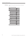
1
TAS 200 Series Adjustment Procedures
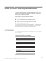
Power Supply Adjustments
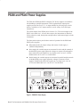
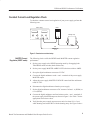
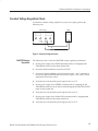
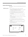
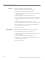
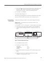
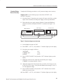
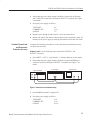
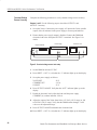
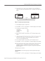
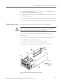
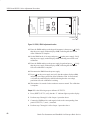
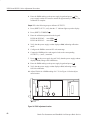
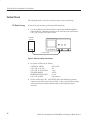
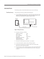
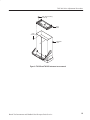
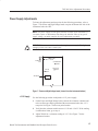
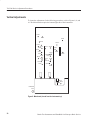
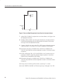
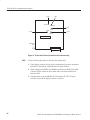
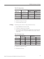
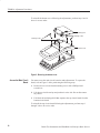
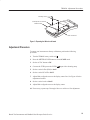
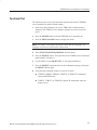
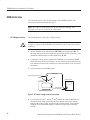
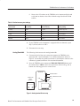
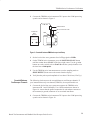
To locate the adjustments and test points for the following procedures, refer to
Figure 7. The Power and High Voltage board occupies the bottom-left side of the
instrument below the CRT.
NOTE. The power supply section affects all other sections of the instrument. If
you make repairs or adjustments that change the absolute value of any power
supply voltage, you must complete the entire adjustment procedure.
WARNING. Use extreme caution when adjusting the power supply. The high
voltages present can cause a fatal injury.
Instrument
front
ASTIG
VR604
FREQ ADJ
VR701
SUB INTENSITY
VR603
+12V ADJ
VR601
SUB FOCUS
VR602
+12V
Test points
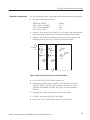
Figure 7: Power and High Voltage board (viewed from the instrument bottom)
+12 V Supply
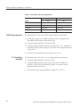
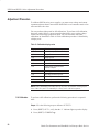
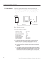
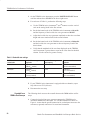
Use the following procedure to adjust the +12 V power supply.
1. On the Power and High Voltage board, connect the voltmeter common lead
to the oscilloscope chassis ground and the measurement lead to the +12 V
test point. See Figure 7 for the test point location.
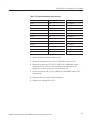
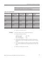
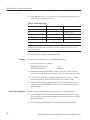
2. Verify that the voltmeter reads between +11.95 and +12.05 V. If the reading
is within these limits, go to step 4.
3. Adjust VR601 for a voltmeter reading of +12 V. See Figure 7 for the
adjustment location.
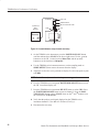
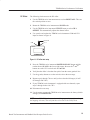
Bench Test Instruments and Handheld Oscilloscopes Basic Service
27