1
PS2520 and PS2521 Series Performance Verification
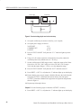
20. Press SHIFT → STORE → 1 to store the above values in the memory 01
location. Verify that the MEMORY, CURRENT (A), and VOLTS readouts
display the values listed in step 19 for memory location 01.
21. Reset the power supply as follows:
VOLTS SET
CURRENT SET
DELAY
6V
5A
3s
22. Press SHIFT → STORE → 2 to store the above values in the memory 02
location. Verify that the MEMORY, CURRENT (A), and VOLTS readouts
display the values set in step 21 for memory location 02.
23. Repeat steps 6 through 12 above.
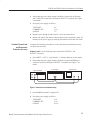
24. Press STEP SET. Set the VOLTS SET to 1 V.
and verify that as you attempt to decrease the voltage
25. Press VOLTS
below 0.00 V, “Err - 018” appears on the CURRENT (A) and VOLTS
readouts. The voltage should decrease in 1 volt steps on the VOLTS readout.
26. Press VOLTS
and verify that as you attempt to increase the voltage past
6.00 V, “Err - 016” appears on readouts. The voltage should increase in
1 volt steps on the VOLTS readout.
27. Press STEP SET. Set the CURRENT SET to .1 A.
28. Press CURRENT
and verify that as you attempt to decrease the current
below 0.000 A, “Err - 019” appears on the readouts and the “C.C.” indicator
lights. The current should decrease in .1 ampere steps on the CURRENT (A)
readout.
and verify that as you attempt to increase the current
29. Press CURRENT
past 5.100 A, “Err - 017” appears on the readouts. The current should
increase in .1 ampere steps on the CURRENT (A) readout.
OCP, Series, and Parallel Mode Indicators. Use the following steps to verify OCP,
series, and parallel output indicator function.
1. On the power supply front panel, press OCP ON/OFF to enable the OCP.
Verify that the “OCP” indicator lights up on the display.
2. Press OCP ON/OFF. Verify that the “OCP” indicator turns off.
3. Press SHIFT → SERIES/INDEP to configure the power supply outputs for
series operation. Verify that the “SERIES” indicator lights up on the display.
4. Press SHIFT → PARA/INDEP to configure the power supply outputs for
parallel operation. Verify that the “PARA” indicator lights up on the display.
34
Bench Test Instruments and Handheld Oscilloscopes Basic Service