1
TAS 200 Series Adjustment Procedures
Horizontal Adjustments
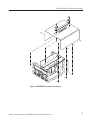
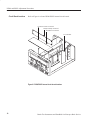
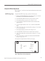
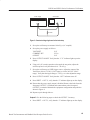
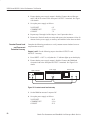
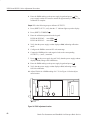
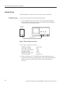
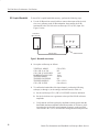
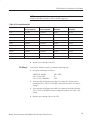
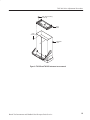
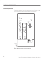
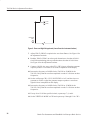
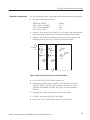
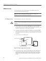
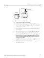
To locate the adjustments for the following procedures, refer to Figures 8 and 10.
The Main board occupies the bottom-right side of the instrument.
X10 MAG Registration
Use the following procedure to adjust the X10 MAG registration.
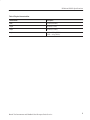
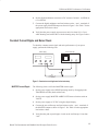
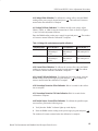
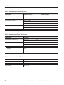
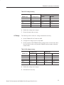
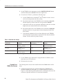
1. Set up the oscilloscope as follows:
VERTICAL MODE
CH 1 VERTICAL POSITION
HORIZONTAL SEC/DIV
CH1
Midrange
1 ms
2. Rotate the HORIZONTAL POSITION control to move the left edge of the
trace to the display center (center vertical graticule line).
3. Set the HORIZONTAL X10 MAG push switch to the in position. Verify that
the trace is located within ±1 division of the display vertical center. If the
trace does not line up, use the HORIZONTAL POSITION control to
reposition the trace to the display center.
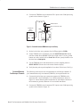
4. Set the HORIZONTAL X10 MAG push switch to the out position. Adjust
VR502 to position the trace edge to the display vertical center. See Figure 8
for the adjustment location.
5. Repeat steps 3 and 4 until the trace edge remains within ±1 division of the
display center when pressing the HORIZONTAL X10 MAG push switch in
and out.
Horizontal Position
Use the following procedure to adjust the horizontal position.
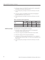
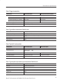
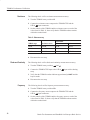
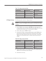
1. Set up the oscilloscope as follows:
VERTICAL MODE
CH 1 VERTICAL POSITION
HORIZONTAL SEC/DIV
CH1
Midrange
1 ms
2. Center the HORIZONTAL POSITION control.
3. Adjust VR408 to align the left edge of the trace to the left-most graticule of
the display. See Figure 8 for the adjustment location.
1 ms Timing
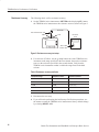
Use the following procedure to adjust the 1 ms timing.
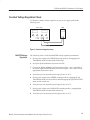
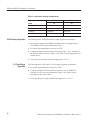
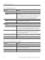
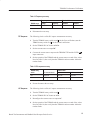
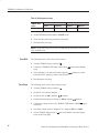
1. Set up the oscilloscope as follows:
VERTICAL MODE
CH 1 VERTICAL POSITION
Bench Test Instruments and Handheld Oscilloscopes Basic Service
CH1
Midrange
37