1
Programmer
TG700
TV Signal Generator Platform
077-0139-06
This document applies to firmware version 5.6
and above.
www.tektronix.com
Copyright © Tektronix. All rights reserved. Licensed software products are owned by Tektronix or its subsidiaries or
suppliers, and are protected by national copyright laws and international treaty provisions.
Tektronix products are covered by U.S. and foreign patents, issued and pending. Information in this publication supercedes
that in all previously published material. Specifications and price change privileges reserved.
TEKTRONIX and TEK are registered trademarks of Tektronix, Inc.
Contacting Tektronix
Tektronix, Inc.
14150 SW Karl Braun Drive
P.O. Box 500
Beaverton, OR 97077
USA
For product information, sales, service, and technical support:
H In North America, call 1-800-833-9200.
H Worldwide, visit www.tektronix.com to find contacts in your area.
Warranty 2
Tektronix warrants that this product will be free from defects in materials and workmanship for a period of one (1)
year from the date of shipment. If any such product proves defective during this warranty period, Tektronix, at its
option, either will repair the defective product without charge for parts and labor, or will provide a replacement in
exchange for the defective product. Parts, modules and replacement products used by Tektronix for warranty work
may be new or reconditioned to like new performance. All replaced parts, modules and products become the
property of Tektronix.
In order to obtain service under this warranty, Customer must notify Tektronix of the defect before the expiration
of the warranty period and make suitable arrangements for the performance of service. Customer shall be
responsible for packaging and shipping the defective product to the service center designated by Tektronix, with
shipping charges prepaid. Tektronix shall pay for the return of the product to Customer if the shipment is to a
location within the country in which the Tektronix service center is located. Customer shall be responsible for
paying all shipping charges, duties, taxes, and any other charges for products returned to any other locations.
This warranty shall not apply to any defect, failure or damage caused by improper use or improper or inadequate
maintenance and care. Tektronix shall not be obligated to furnish service under this warranty a) to repair damage
resulting from attempts by personnel other than Tektronix representatives to install, repair or service the product;
b) to repair damage resulting from improper use or connection to incompatible equipment; c) to repair any
damage or malfunction caused by the use of non-Tektronix supplies; or d) to service a product that has been
modified or integrated with other products when the effect of such modification or integration increases the time
or difficulty of servicing the product.
THIS WARRANTY IS GIVEN BY TEKTRONIX WITH RESPECT TO THE PRODUCT IN LIEU OF ANY
OTHER WARRANTIES, EXPRESS OR IMPLIED. TEKTRONIX AND ITS VENDORS DISCLAIM ANY
IMPLIED WARRANTIES OF MERCHANTABILITY OR FITNESS FOR A PARTICULAR PURPOSE.
TEKTRONIX’ RESPONSIBILITY TO REPAIR OR REPLACE DEFECTIVE PRODUCTS IS THE SOLE AND
EXCLUSIVE REMEDY PROVIDED TO THE CUSTOMER FOR BREACH OF THIS WARRANTY.
TEKTRONIX AND ITS VENDORS WILL NOT BE LIABLE FOR ANY INDIRECT, SPECIAL, INCIDENTAL,
OR CONSEQUENTIAL DAMAGES IRRESPECTIVE OF WHETHER TEKTRONIX OR THE VENDOR HAS
ADVANCE NOTICE OF THE POSSIBILITY OF SUCH DAMAGES.
Table of Contents
Preface . . . . . . . . . . . . . . . . . . . . . . . . . . . . . . . . . . . . . . . . . . . . . . . . . . .
v
Related Manuals . . . . . . . . . . . . . . . . . . . . . . . . . . . . . . . . . . . . . . . . . . . . . . . . .
v
Getting Started . . . . . . . . . . . . . . . . . . . . . . . . . . . . . . . . . . . . . . . . . . . .
1--1
Overview of the Manual . . . . . . . . . . . . . . . . . . . . . . . . . . . . . . . . . . . . . . . . . . .
Connecting the Interface . . . . . . . . . . . . . . . . . . . . . . . . . . . . . . . . . . . . . . . . . .
1-- 1
1-- 2
Getting Started
Syntax and Commands
TG700 Syntax . . . . . . . . . . . . . . . . . . . . . . . . . . . . . . . . . . . . . . . . . . . . .
2--1
Programming Model . . . . . . . . . . . . . . . . . . . . . . . . . . . . . . . . . . . . . . . . . . . . . .
SCPI Commands and Queries . . . . . . . . . . . . . . . . . . . . . . . . . . . . . . . . . . . . . .
IEEE 488.2 Common Commands . . . . . . . . . . . . . . . . . . . . . . . . . . . . . . . . . . .
Constructed Mnemonics . . . . . . . . . . . . . . . . . . . . . . . . . . . . . . . . . . . . . . . . . . .
Block Arguments . . . . . . . . . . . . . . . . . . . . . . . . . . . . . . . . . . . . . . . . . . . . . . . .
Special Characters . . . . . . . . . . . . . . . . . . . . . . . . . . . . . . . . . . . . . . . . . . . . . . .
2-- 2
2-- 4
2-- 9
2-- 10
2-- 10
2-- 11
TG700 Remote Commands . . . . . . . . . . . . . . . . . . . . . . . . . . . . . . . . . .
2--13
Common Commands . . . . . . . . . . . . . . . . . . . . . . . . . . . . . . . . . . . . . . . . . . . . .
DISPLAY Commands . . . . . . . . . . . . . . . . . . . . . . . . . . . . . . . . . . . . . . . . . . . . .
INSTRUMENT Commands . . . . . . . . . . . . . . . . . . . . . . . . . . . . . . . . . . . . . . . .
MASS MEMORY Commands . . . . . . . . . . . . . . . . . . . . . . . . . . . . . . . . . . . . . .
PROGRAM Commands . . . . . . . . . . . . . . . . . . . . . . . . . . . . . . . . . . . . . . . . . . .
SENSE Commands . . . . . . . . . . . . . . . . . . . . . . . . . . . . . . . . . . . . . . . . . . . . . . .
STATUS Commands . . . . . . . . . . . . . . . . . . . . . . . . . . . . . . . . . . . . . . . . . . . . . .
SYSTEM Commands . . . . . . . . . . . . . . . . . . . . . . . . . . . . . . . . . . . . . . . . . . . . .
2-- 13
2-- 15
2-- 16
2-- 17
2-- 20
2-- 21
2-- 22
2-- 25
AG7 Audio Generator Module Remote Commands . . . . . . . . . . . . .
2--27
OUTPUT Commands . . . . . . . . . . . . . . . . . . . . . . . . . . . . . . . . . . . . . . . . . . . . .
SENSE Commands . . . . . . . . . . . . . . . . . . . . . . . . . . . . . . . . . . . . . . . . . . . . . . .
2-- 27
2-- 29
AGL7 Analog Genlock Module Remote Commands . . . . . . . . . . . . .
2--31
INPUT Commands . . . . . . . . . . . . . . . . . . . . . . . . . . . . . . . . . . . . . . . . . . . . . . .
SOURCE Commands . . . . . . . . . . . . . . . . . . . . . . . . . . . . . . . . . . . . . . . . . . . . .
OUTPUT Commands . . . . . . . . . . . . . . . . . . . . . . . . . . . . . . . . . . . . . . . . . . . . .
SENSE Commands . . . . . . . . . . . . . . . . . . . . . . . . . . . . . . . . . . . . . . . . . . . . . . .
2-- 31
2-- 33
2-- 34
2-- 36
ATG7 Analog Test Generator Module Remote Commands . . . . . . .
2--39
MASS MEMORY Commands . . . . . . . . . . . . . . . . . . . . . . . . . . . . . . . . . . . . . .
OUTPUT Commands . . . . . . . . . . . . . . . . . . . . . . . . . . . . . . . . . . . . . . . . . . . . .
SENSE Commands . . . . . . . . . . . . . . . . . . . . . . . . . . . . . . . . . . . . . . . . . . . . . . .
2-- 39
2-- 40
2-- 44
AVG7 Analog Video Generator Module Remote Commands . . . . . .
2--47
MASS MEMORY Commands . . . . . . . . . . . . . . . . . . . . . . . . . . . . . . . . . . . . . .
OUTPUT Commands . . . . . . . . . . . . . . . . . . . . . . . . . . . . . . . . . . . . . . . . . . . . .
SENSE Commands . . . . . . . . . . . . . . . . . . . . . . . . . . . . . . . . . . . . . . . . . . . . . . .
2-- 47
2-- 48
2-- 54
AWVG7 Analog Wideband Video Generator Module
Remote Commands . . . . . . . . . . . . . . . . . . . . . . . . . . . . . . . . . . . . .
2--57
MASS MEMORY Commands . . . . . . . . . . . . . . . . . . . . . . . . . . . . . . . . . . . . . .
OUTPUT Commands . . . . . . . . . . . . . . . . . . . . . . . . . . . . . . . . . . . . . . . . . . . . .
SENSE Commands . . . . . . . . . . . . . . . . . . . . . . . . . . . . . . . . . . . . . . . . . . . . . . .
2-- 57
2-- 58
2-- 63
TG700 TV Signal Generator Platform Programmer Manual
i
Table of Contents
BG7 Black Generator Module Remote Commands . . . . . . . . . . . . . .
2--65
OUTPUT Commands . . . . . . . . . . . . . . . . . . . . . . . . . . . . . . . . . . . . . . . . . . . . .
SENSE Commands . . . . . . . . . . . . . . . . . . . . . . . . . . . . . . . . . . . . . . . . . . . . . . .
2-- 65
2-- 68
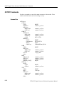
DVG7 Digital Video Generator Module Remote Commands . . . . . .
2--71
MASS MEMORY Commands . . . . . . . . . . . . . . . . . . . . . . . . . . . . . . . . . . . . . .
OUTPUT Commands . . . . . . . . . . . . . . . . . . . . . . . . . . . . . . . . . . . . . . . . . . . . .
SENSE Commands . . . . . . . . . . . . . . . . . . . . . . . . . . . . . . . . . . . . . . . . . . . . . . .
2-- 71
2-- 72
2-- 82
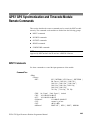
GPS7 GPS Synchronization and Timecode Module
Remote Commands . . . . . . . . . . . . . . . . . . . . . . . . . . . . . . . . . . . . .
2--85
INPUT Commands . . . . . . . . . . . . . . . . . . . . . . . . . . . . . . . . . . . . . . . . . . . . . . .
SOURCE Commands . . . . . . . . . . . . . . . . . . . . . . . . . . . . . . . . . . . . . . . . . . . . .
OUTPUT Commands . . . . . . . . . . . . . . . . . . . . . . . . . . . . . . . . . . . . . . . . . . . . .
SENSE Commands . . . . . . . . . . . . . . . . . . . . . . . . . . . . . . . . . . . . . . . . . . . . . . .
2-- 85
2-- 90
2-- 99
2-- 104
HD3G7 3 Gb/s SDI Video Generator Module
Remote Commands . . . . . . . . . . . . . . . . . . . . . . . . . . . . . . . . . . . . .
2--107
OUTPUT Commands . . . . . . . . . . . . . . . . . . . . . . . . . . . . . . . . . . . . . . . . . . . . .
SENSE Commands . . . . . . . . . . . . . . . . . . . . . . . . . . . . . . . . . . . . . . . . . . . . . . .
DIAGNOSTIC Commands . . . . . . . . . . . . . . . . . . . . . . . . . . . . . . . . . . . . . . . . .
2-- 107
2-- 132
2-- 134
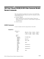
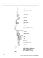
HDLG7 HD Dual Link Video Generator Module
Remote Commands . . . . . . . . . . . . . . . . . . . . . . . . . . . . . . . . . . . . .
2--137
OUTPUT Commands . . . . . . . . . . . . . . . . . . . . . . . . . . . . . . . . . . . . . . . . . . . . .
SENSE Commands . . . . . . . . . . . . . . . . . . . . . . . . . . . . . . . . . . . . . . . . . . . . . . .
Command Examples . . . . . . . . . . . . . . . . . . . . . . . . . . . . . . . . . . . . . . . . . . . . . .
2-- 137
2-- 144
2-- 145
HDVG7 HDTV Digital Video Generator Module
Remote Commands . . . . . . . . . . . . . . . . . . . . . . . . . . . . . . . . . . . . .
2--147
MASS MEMORY Commands . . . . . . . . . . . . . . . . . . . . . . . . . . . . . . . . . . . . . .
OUTPUT Commands . . . . . . . . . . . . . . . . . . . . . . . . . . . . . . . . . . . . . . . . . . . . .
SENSE Commands . . . . . . . . . . . . . . . . . . . . . . . . . . . . . . . . . . . . . . . . . . . . . . .
2-- 147
2-- 147
2-- 157
SDI7 Dual Channel SD/HD/3G SDI Video Generator Module
Remote Commands . . . . . . . . . . . . . . . . . . . . . . . . . . . . . . . . . . . . .
2--161
OUTPUT Commands . . . . . . . . . . . . . . . . . . . . . . . . . . . . . . . . . . . . . . . . . . . . .
SENSE Commands . . . . . . . . . . . . . . . . . . . . . . . . . . . . . . . . . . . . . . . . . . . . . . .
2-- 161
2-- 189
Error Messages and Codes
Error Messages and Codes . . . . . . . . . . . . . . . . . . . . . . . . . . . . . . . . . .
3--1
Command Errors . . . . . . . . . . . . . . . . . . . . . . . . . . . . . . . . . . . . . . . . . . . . . . . . .
Execution Errors . . . . . . . . . . . . . . . . . . . . . . . . . . . . . . . . . . . . . . . . . . . . . . . . .
Device Specific Errors . . . . . . . . . . . . . . . . . . . . . . . . . . . . . . . . . . . . . . . . . . . .
Query Errors . . . . . . . . . . . . . . . . . . . . . . . . . . . . . . . . . . . . . . . . . . . . . . . . . . . .
Device Errors . . . . . . . . . . . . . . . . . . . . . . . . . . . . . . . . . . . . . . . . . . . . . . . . . . .
3-- 1
3-- 2
3-- 4
3-- 5
3-- 5
Index
ii
TG700 TV Signal Generator Platform Programmer Manual
Table of Contents
List of Figures
Figure 1--1: Command parts . . . . . . . . . . . . . . . . . . . . . . . . . . . . . . . . .
Figure 1--2: 10 Base-T connector (rear panel) . . . . . . . . . . . . . . . . . . .
1--1
1--2
Figure 2--1: Example of SCPI subsystem hierarchy tree . . . . . . . . . .
2--4
Figure 2--2: Example of abbreviating a command . . . . . . . . . . . . . . .
2--6
Figure 2--3: Example of chaining commands and queries . . . . . . . . .
2--7
Figure 2--4: Example of omitting root and lower-level nodes in a chained
message . . . . . . . . . . . . . . . . . . . . . . . . . . . . . . . . . . . . . . . . . . . . . . .
2--7
TG700 TV Signal Generator Platform Programmer Manual
iii
Table of Contents
List of Tables
iv
Table 2--1: Parameter types used in syntax descriptions . . . . . . . . .
Table 2--2: BNF symbols and meanings . . . . . . . . . . . . . . . . . . . . . . .
Table 2--3: GPS7 Source horizontal offset ranges . . . . . . . . . . . . . . .
Table 2--4: GPS7 Output horizontal offset ranges . . . . . . . . . . . . . . .
Table 2--5: GPS7 Vertical timing offset ranges . . . . . . . . . . . . . . . . .
Table 2--6: HD3G7 Horizontal offset ranges . . . . . . . . . . . . . . . . . . .
Table 2--7: SDI7 Horizontal offset ranges . . . . . . . . . . . . . . . . . . . . . .
Table 2--8: SDI7 Vertical offset ranges . . . . . . . . . . . . . . . . . . . . . . . .
2--5
2--9
2--92
2--104
2--106
2--132
2--189
2--190
Table 3--1: Command errors . . . . . . . . . . . . . . . . . . . . . . . . . . . . . . . .
Table 3--2: Execution errors . . . . . . . . . . . . . . . . . . . . . . . . . . . . . . . . .
Table 3--3: Device specific errors . . . . . . . . . . . . . . . . . . . . . . . . . . . . .
Table 3--4: Query errors . . . . . . . . . . . . . . . . . . . . . . . . . . . . . . . . . . . .
Table 3--5: Device errors . . . . . . . . . . . . . . . . . . . . . . . . . . . . . . . . . . . .
3--1
3--2
3--4
3--5
3--5
TG700 TV Signal Generator Platform Programmer Manual
Preface
This manual provides programming information for the TG700 TV Signal
Generator Platform and related modules.
Related Manuals
The following documents are also available for the TG700 and related modules:
H
The TG700 TV Signal Generator User Manual (Tektronix part number
071-1970-XX) describes how to install the instrument and how to operate
the mainframe and modules.
H
The TG700 TV Signal Generator Platform PC Tools Technical Reference
(Tektronix part number 077-0138-XX) describes how to use the PC tools
that are available for the mainframe and related modules.
H
The TG700 TV Signal Generator Platform Specifications and Performance
Verification Technical Reference (Tektronix part number 077-0137-XX)
describes the mechanical, electrical, and environmental specifications for the
mainframe and related modules. This manual also provides performance
verification procedures.
H
The TG700 TV Signal Generator Platform Programmer Manual (Tektronix
part number 077-0139-XX) provides programming information for the
mainframe and related modules.
H
The TG700 TV Signal Generator Platform Service Manual (Tektronix part
number 077-0230-XX) describes how to service the TG700 mainframe to the
module level (circuit boards, fuses). Specific service information for a
module is located in a subsection of the Service manual specific to the
module.
H
The TG700 TV Signal Generator Platform Release Notes (Tektronix part
number 077-0228-XX English; 077-0443-XX Japanese) describes the new
features, improvements, and limitations of the most recent available
firmware for the TG700 TV Signal Generator Platform.
H
The Video Sync Pulse Generator & Electronic Changeover Unit System
Integration Technical Reference (Tektronix part number 077--0563--XX)
provides information for system integrators who are designing systems for
high-definition (HD) and standard-definition (SD) digital video content
where Tektronix electronic changeover units and video sync pulse generators
are to be deployed.
TG700 TV Signal Generator Platform Programmer Manual
v
Preface
vi
TG700 TV Signal Generator Platform Programmer Manual
Getting Started
Getting Started
To help you get started with programming the TG700, this section includes the
following subsections:
H
Overview of the Manual
Summarizes each major section of this manual.
H
Connecting the Interface
Describes how to physically connect the analyzer to a controller.
Overview of the Manual
The information contained in each major section of this manual is described
below.
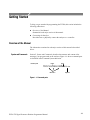
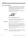
Syntax and Commands
Section 2, Syntax and Commands, describes the structure and content of the
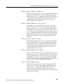
messages your program sends to the analyzer. Figure 1--1 shows command parts
as described in the Command Syntax subsection.
Command parts
Header
Space
:CALCulate:MARKer:MODE ABSolute
Mnemonics
Argument
Figure 1- 1: Command parts
TG700 TV Signal Generator Platform Programmer Manual
1- 1
Getting Started
Section 2 also describes the effect of each command and provides examples of
how you might use it.
Error Messages and
Codes
The program may request information from the instrument. The instrument
provides information in the form of status and error messages. Section 3, Status
and Events, describes how to get status or event information from the program
and details the event and error messages.
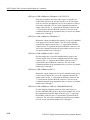
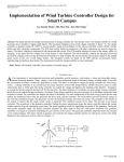
Connecting the Interface
The TG700 has a 10 BASE-T port on the rear panel that allows you to control
the instrument remotely, using your PC to upload and download various files
such as signal files or logo files. For details on connecting to this port, see the
TG700 TV Signal Generator Platform User Manual, Tektronix part number
071-1970-XX.
10 BASE-T port
Figure 1- 2: 10 Base-T connector (rear panel)
1- 2
TG700 TV Signal Generator Platform Programmer Manual
Syntax and Commands
TG700 Syntax
This section contains information on the Standard Commands for Programmable
Instruments (SCPI) and IEEE 488.2 Common Commands you can use to
program your TG700. The information is organized in the following subsections:
H
Programming Model -- This subsection provides information on programming prerequisites
H
SCPI Commands and Queries -- This subsection describes the SCPI
command organization and syntax
H
IEEE 488.2 Common Commands -- This subsection lists the commands and
argument structures that are common to all SCPI commands
H
Constructed Mnemonics -- This subsection describes the usage of constructed
mnemonics by the TG700.
H
Block Arguments -- This subsection describes the usage of block arguments
by the TG700.
H
Special Characters -- This subsection lists the special character sets that are
used by the remote control interface.
TG700 TV Signal Generator Platform Programmer Manual
2- 1
TG700 Syntax
Programming Model
Specific conditions must exist before programming commands will affect the test
signal generated by a module.
Selecting the Module
Command Arguments
Select the module to be addressed before executing any commands. Many of the
commands used by the TG700 are shared by several modules and will be
accepted without a reported error.
Many commands accept either string or numeric arguments. For example: a
boolean argument can either be “1” or “ON”.
Signal parameter commands that have a :STEP node can accept either a numeric
value or a string argument that refers to the :STEP increment.
Select signal parameter commands accept either a numeric value or one of the
following strings:
UP. Use this argument to increase the parameter value one increment as defined
by the :STEP value.
DOWN. Use this argument to decrease the parameter value one increment as
defined by the :STEP value.
MINimum. Use this argument to query the minimum value or set the parameter
value to the minimum acceptable value.
MAXimum. Use this argument to query the maximum value or set the parameter
value to the maximum acceptable value.
DEFault. Use this argument to query the default value or set the parameter value
to the default value.
NOTE. If the TG700 does not return a value in response to a MIN or MAX query,
then the values are undefined and an error message is generated.
2- 2
TG700 TV Signal Generator Platform Programmer Manual
TG700 Syntax
Query Arguments
If you send a query with no argument, the response is the current value.
You can also use MINimum, MAXimum, and DEFault as arguments for queries
whose command form can use these arguments (refer to the command syntax for
the specific command). Instead of returning the current value, queries using these
arguments return the following information:
MINimum. Returns the minimum acceptable value.
MAXimum. Returns the maximum acceptable value.
DEFault. Returns the default value.
Argument Example
The following example demonstrates the effect of each of the arguments when
used with a step value.
1. selects the HDTV digital video generator
module located in the slot number indicated by the “#” symbol.
2. displays a circle on the video display.
NOTE. :OUTPut:CIRCle:DIAMeter uses an argument that is the percent of
picture height.
3. ! sets the circle diameter to 90 percent
of the screen height.
4. "# sets the step increment to 10 percent.
5. $ changes the circle diameter to 80 percent
of the screen height.
6. %# changes the circle diameter to 50 percent of
the screen height.
7. &' changes the circle diameter to
100 percent of the screen height.
8. ' changes the circle diameter to
0 percent of the screen height.
9. changes the circle diameter to 10 percent of
the screen height.
10. ( &' queries the maximum circle
diameter (not the current diameter). The query returns the value of
100 percent, which is the maximum circle diameter allowable.
TG700 TV Signal Generator Platform Programmer Manual
2- 3
TG700 Syntax
SCPI Commands and Queries
SCPI is a standard created by a consortium that provides guidelines for remote
programming of instruments. These guidelines provide a consistent programming environment for instrument control and data transfer. This environment
uses defined programming messages, instrument responses, and data format
across all SCPI instruments, regardless of manufacturer. The TG700 uses a
command language based on the SCPI standard.
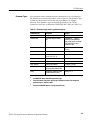
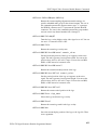
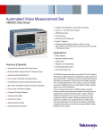
The SCPI language is based on a hierarchical or tree structure (see Figure 2--1)
that represents a subsystem. The top level of the tree is the root node; it is
followed by one or more lower-level nodes.
STATe
OUTPut
Root node
CIRCle
Lower-level
nodes
DIAMeter POSition
Figure 2- 1: Example of SCPI subsystem hierarchy tree
You can create commands and queries from these subsystem hierarchy trees.
Commands specify actions for the instrument to perform. Queries return
measurement data and information about parameter settings.
Creating Commands
SCPI commands are created by stringing together the nodes of a subsystem
hierarchy and separating each node by a colon.
In Figure 2--1, OUTPut is the root node and CIRCle, STATe, DIAMeter, and
POSition are lower-level nodes. To create a SCPI command, start with the root
node OUTPut and move down the tree structure adding nodes until you reach the
end of a branch. Most commands and some queries have parameters; you must
include a value for these parameters. If you specify a parameter value that is out
of range, the parameter will be set to a default value.
For example, OUTPut:CIRCle:STATe ON is a valid SCPI command created
from the hierarchy tree in Figure 2--1.
Creating Queries
2- 4
To create a query, start at the root node of a tree structure, move down to the end
of a branch, and add a question mark. OUTPut:CIRCle:STATe? is an example of
a valid SCPI query using the hierarchy tree in Figure 2--1.
TG700 TV Signal Generator Platform Programmer Manual
TG700 Syntax
Parameter Types
Every parameter in the command and query descriptions is of a specified type.
The parameters are enclosed in brackets, such as <pattern>. The parameter type
is listed after the parameter and is enclosed in parentheses, for example,
(discrete). Some parameter types are defined specifically for the TG700
command set and some are defined by ANSI/IEEE 488.2-1987 (see Table 2--1).
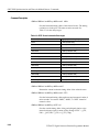
Table 2- 1: Parameter types used in syntax descriptions
Parameter type
Description
Example
binary
Binary numbers
#B0110
A specified length of arbitrary
data
#512234xxxxx . . . where 5
indicates that the following 5
digits (12234) specify the length
of the data in bytes; xxxxx ...
indicates the data
boolean
Boolean numbers or values
ON or 1
OFF or 0
discrete
A list of specific values
MIN, MAX, UP, DOWN
hexadecimal2
Hexadecimal numbers
(0-- 9, A, B, C, D, E, F)
#HAA, #H1
NR12,3 numeric
Integers
0, 1, 15, - 1
NR22 numeric
Decimal numbers
1.2, 3.141516, - 6.5
NR32
Floating point numbers
3.1415E-- 9, - 16.1E5
NRf2 numeric
Flexible decimal number that
may be type NR1, NR2 or NR3
See NR1, NR2, NR3 examples
string4
Alphanumeric characters (must
be within quotation marks)
“Testing 1, 2, 3”
arbitrary
block1
numeric
1
Defined in ANSI/IEEE 488.2 as “Definite Length Arbitrary Block Response Data.”
2
An ANSI/IEEE 488.2- 1992-defined parameter type.
3
Some commands and queries will accept a hexadecimal value even though the
parameter type is defined as NR1.
4
Defined in ANSI/IEEE 488.2 as “String Response Data.”
TG700 TV Signal Generator Platform Programmer Manual
2- 5
TG700 Syntax
Abbreviating Commands,
Queries, and Parameters
You can abbreviate most SCPI commands, queries, and parameters to an
accepted short form. This manual shows these short forms as a combination of
upper and lower case letters. The upper case letters indicate the accepted short
form of a command. As shown in Figure 2--2, you can create a short form by
using only the upper case letters. The accepted short form and the long form are
equivalent and request the same action of the instrument.
Long form of a
command
OUTPut:EAUDio:CHANnel2:AMPLitude 10
Minimum information needed
for accepted short form
Accepted short form
of a command and
parameter
OUTP:EAUD:CHAN2:AMPL 10
Figure 2- 2: Example of abbreviating a command
NOTE. The numeric suffix of a command or query may be included in either the
long form or short form; the TG700 will default to “1” if no suffix is used. In
Figure 2--2, the “2” of “CHAN2” indicates that the command is directed to the
second channel..
2- 6
TG700 TV Signal Generator Platform Programmer Manual
TG700 Syntax
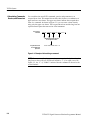
Chaining Commands and
Queries
You can chain several commands or queries together into a single message. To
create a chained message, first create a command or query, add a semicolon (;),
and then add more commands or queries and semicolons until you are done. If
the command following a semicolon is a root node, precede it with a colon (:).
Figure 2--3 illustrates a chained message consisting of several commands and
queries. The single chained message should end in a command or query, not a
semicolon. Responses to any queries in your message are separated by semicolons.
:OUTP:CIRC:DIAM 75;:OUTP:EAUD:STAT ON;:OUTP:EAUD:GRRO:NBIT?;:OUTP:LOGO:POS:HOR?
First command
Second command
First query
The response from this chained
message might be
Second query
24;-35
Response from first query
Response from second query
Figure 2- 3: Example of chaining commands and queries
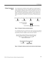
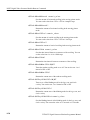
If a command has the same root and lower-level nodes as the previous command,
you can omit these nodes. In Figure 2--4, the second command has the same root
node (CIRC) as the first command, so these nodes can be omitted.
:OUTP:CIRC:DIAM 25;:OUTP:CIRC:POS:VERT 25;:OUTP:CIRC:STAT ON
Identical root and lower-level nodes
:OUTP:CIRC:DIMA 25;POS:VERT 25;STAT ON
First command
Additional commands
(omitting the root nodes)
Figure 2- 4: Example of omitting root and lower-level nodes in a chained message
TG700 TV Signal Generator Platform Programmer Manual
2- 7
TG700 Syntax
General Rules
Here are three general rules for using SCPI commands, queries, and parameters:
H
H
You can use single (‘ ’) or double (“ ”) quotation marks for quoted strings,
but you cannot use both types of quotation marks for the same string.
correct:
“This string uses quotation marks correctly.”
correct:
‘This string also uses quotation marks correctly.’
incorrect:
“This string does not use quotation marks correctly.’
You can use upper case, lower case, or a mixture of both cases for all
commands, queries, and parameters.
&) *%
is the same as
+,
-,+.''+/+'0+! *%
and
-,+.''+) *%
NOTE. Literal strings (quoted) are case sensitive. For example: file names.
H
2- 8
No embedded spaces are allowed between or within nodes.
correct:
&) *%
incorrect:
& ) *%
TG700 TV Signal Generator Platform Programmer Manual
TG700 Syntax
IEEE 488.2 Common Commands
Description
ANSI/IEEE Standard 488.2 defines the codes, formats, protocols, and usage of
common commands and queries used on the interface between the controller and
the instruments. The TG700 complies with this standard.
Command and Query
Structure
The syntax for an IEEE 488.2 common command is an asterisk (*) followed by a
command and, optionally, a space and parameter value. The syntax for an
IEEE 488.2 common query is an asterisk (*) followed by a query and a question
mark. All of the common commands and queries are listed in the last part of the
Syntax and Commands section. The following are examples of common
commands:
H
1 "2
H
1
The following are examples of common queries:
Backus-Naur Form
Definition
H
1(
H
1(
This manual may describe commands and queries using the Backus-Naur Form
(BNF) notation. Table 2--2 defines the standard BNF symbols:
Table 2- 2: BNF symbols and meanings
Symbol
Meaning
<
Defined element
::=
Is defined as
|
Exclusive OR
{
Message Terminators
>
}
Group; one element is required
[ ]
Optional; can be omitted
. . .
Previous element(s) may be repeated
(
Comment
)
This manual uses <EOM> (End of message) to represent a message terminator.
Symbol
Meaning
<EOM>
Message terminator
TG700 TV Signal Generator Platform Programmer Manual
2- 9
TG700 Syntax
The end-of-message terminator may be the ASCII code for line feed (LF) sent as
the last data byte. The TG700 always terminates messages with LF. It allows
white space before the terminator.
Constructed Mnemonics
Some header mnemonics specify one of a range of mnemonics. For example, an
audio channel mnemonic can be either CHANnel1, CHANnel2, CHANnel3, or
CHANnel4.You use these mnemonics in the command just as you do any other
mnemonic. For example, there is a "( query, and there
is also an *( query. In the command descriptions, this
list of choices is abbreviated as 34. The value of <n> is the upper range
of valid suffixes. If the numeric suffix is omitted, the TG700 uses the default
value of “1”.
Block Arguments
Several TG700 commands use a block argument form:
Symbol
Meaning
<NZDig>
A non-zero digit character, in the range 1-- 9
<Dig>
A digit character, in the range 0-- 9
<DChar>
A character with the hex equivalent of 00 through FF
hexadecimal (0 through 255 decimal)
<Block>
A block of data bytes, defined as:
<Block> ::=
{ #<NZDig><Dig>[<Dig>...][<DChar>...]
| #0[<DChar>...]<terminator> }
3)'54 specifies the number of 3'54 elements that follow. Taken together, the
3'54 elements form a decimal integer that specifies how many 3/!4
elements follow.
2- 10
TG700 TV Signal Generator Platform Programmer Manual
TG700 Syntax
Special Characters
The remote control interface handles characters differently than the front panel or
SDP2000 software.
Standard symbol (ASCII)
Remote control sequence
/
(47)
‘s
\
(92)
‘b
-
(45)
‘h
‘
(96)
’’
:
(58)
‘c
Line return
^
(94)
Signal names created from SDP2000 software will be displayed as created.
Signals created or displayed using the SCPI interface use the remote control
sequence.
For example: “SinX/X” is displayed as “SinX/X” via the front panel or SDP2000
software; however, “SinX/X” is displayed as “SinX‘sX” via when using SCPI.
Use the caret symbol “^” as a line return when naming buttons and signals.
TG700 TV Signal Generator Platform Programmer Manual
2- 11
TG700 Syntax
2- 12
TG700 TV Signal Generator Platform Programmer Manual
TG700 Remote Commands
This section describes the remote command set used in the TG700. The
commands for the TG700 are divided into the following eight groups:
H
Common commands
H
DISPLAY commands
H
INSTRUMENT commands
H
MASS MEMORY commands
H
PROGRAM commands
H
SENSE commands
H
STATUS commands
H
SYSTEM commands
The TG700 can be controlled remotely through the Ethernet interface on the rear
panel. Refer to the TG700 TV Signal Generator User Manual, Tektronix part
number 071-1970-XX, for detailed information about how to connect and set up
for remote operation.
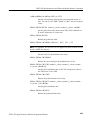
Common Commands
The Common commands have a “*” prefix and address all of the installed
modules.
Command Tree
*CLS
*ESE(?)
*ESR?
*IDN?
*OPC(?)
*OPT?
*RST
*SRE(?)
*STB?
*TST?
*WAI
TG700 TV Signal Generator Platform Programmer Manual
2- 13
TG700 Remote Commands
Command Description
1
Clears SESR (Standard Event Status Register), the SBR (Status Byte
Register), and Event Queue, which are used in the instrument status
and event reporting system.
1
Sets the bits of the ESER (Event Status Enable Register) used in the
status and events reporting system.
1(
Returns the contents of the ESER.
1(
Returns the contents of SESR (Standard Event Status Register) used
in the status and events reporting system.
1(
Returns the ID information of the instrument.
1
Causes bit 0 in the SESR (Standard Event Status Register) to be set ,
and the operation complete message to be issued, when all pending
operations are finished.
1(
Waits until all pending operations are finished and returns a “1 ”
ASCII character.
1(
Lists all of the occupied slots in the TG700 and the nomenclature,
slot, hardware version, and software version of the installed
modules.
Each field is a slot. Each field is separated by commas. The
information within a field is colon delimited, as in “<nomenclature>:<slot>:<hw>:<sw>”.
1
Resets the instrument to the default state.
2- 14
TG700 TV Signal Generator Platform Programmer Manual
TG700 Remote Commands
1
Sets the bits of the SRER (Service Request Enable Register).
1(
Returns the contents of SRER.
16(
Returns the value of the SBR (Status Byte Register). Bit 6 of the
SBR is read as a MSS (Master Status Summary) bit.
1(
Self-test query. This query does not perform any tests; however, this
query is accepted as a valid command to comply with IEEE 488.2
requirements.
1$
Wait-to-continue command. This command is not necessary since
the TG700 handles commands sequentially; however, this query is
accepted as a valid command to comply with IEEE 488.2 requirements.
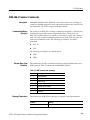
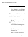
DISPLAY Commands
Use these commands to control the contrast and backlight settings of the LCD
display.
Command Tree
:DISPlay
:BACKlight
ON|OFF
:CONTrast
<numeric_value>
[:WINDow][:TEXT][:DATA] <message>
Command Description
!768'5/ 9
Turns the LCD display backlight on or off. You can use 1 or 0
instead of ON or OFF.
!768'5/(
Returns the current status of the backlight.
TG700 TV Signal Generator Platform Programmer Manual
2- 15
TG700 Remote Commands
!7!. 3
':;!
4
Controls the intensity of the front-panel LCD display. The value
should be an integer number between 1 and 40.
!7!.(
Returns the current contrast value.
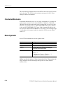
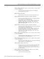
INSTRUMENT Commands
Use these commands to list, identify, and query modules.
Command Tree
:INSTrument
:CATalog?
:FULL?
[:SELect] <module_name>
:NSELect <slot_number>
Command Description
!+5(
Returns a comma delimited list of all slots that are occupied by
modules.
!+5 (
Returns a comma delimited list of module names and slot numbers,
in pairs. The string type of module and the numeric suffix indicates
the slot. For example, “AGL7:1”, 1, “HDVG7:2”, 2 indicates a
AGL7 in slot 1, and a HDVG7 in slot 2.
<
= 3+>
:!
4
Selects a module by name.
<
=(
Returns a module by name.
3.+:?
4
Select a module by slot number.
2- 16
TG700 TV Signal Generator Platform Programmer Manual
TG700 Remote Commands
(
Returns a module by slot number.
MASS MEMORY Commands
All signal movement within the memory is accomplished by copying all
appropriate files of the named signal(s) to the new location. The signal tree is
traversable and the use of wildcards permits copying or storing individual signals
or the entire module signal list.
Command Tree
:MMEMory
:CATalog?
:CDIRectory
:COPY
:DATA
:DELete
:LOAD
:DOWNload
:PRESet
:SIGNal
:MDIRectory
:MOVe
:RDIRectory
:SIGNal
:ACTive?
:STORe
:PRESet
:PRESet
:CATalog?
:ALL?
:DELete
:REName
[<directory_path>]
<directory_path>
<source>,<destination>
<file_name>,<block_data>
<file_name>
<block_data>
<preset_ID>|<preset_name>
<module_name>,<signal_name>
<directory_path>
<from_filename>,<to_filename>
<directory_path>
<signal_name>
<preset_ID>|<preset_name>
<preset_ID>
<preset_ID>|<preset_name>
<preset_ID>,<preset_name>
The argument <signal_name> is the full or partial path name to a signal found in
a module. The argument <file_name> is the MS-DOS compatible naming
convention. For example, the syntax for a complete path would be:
module_type/signal_set/button/test_signal
H
module_type is the directory level for a given module type
H
signal_set is the directory level for different sets of signals
H
button is the directory level for different buttons
H
test_signal is the directory level for different test signals
TG700 TV Signal Generator Platform Programmer Manual
2- 17
TG700 Remote Commands
Command Description
+7!+5( <3>'
+7:,!/4=
Lists the current directory level. If at the top level, it returns a list of
signal sets and the other files and directories for the module partition
you are currently in. If in a Signal Set directory, it returns a list of
buttons. If in a button directory, it returns a list of test signals.
Query response -- <used_bytes>, <available_bytes>, <file_name1>,,
<file_size1>, <file_name2>,, <file_size2>
+7
+7 <3>'
+7:,!/4=
Changes the current working directory.
+7
+7(
Returns the current working directory path.
+7@ 3.+
4A3>
.'!'+4
Copies a file within the TG700 file system. Wildcards are not
supported.
This command is provided to support sequence files and is not
recommended for use with signal files.
+7 3B'
:!
4A3?+C:>!!4
Loads data created by a PC to the flash memory of the TG700 with
the specified file name. The file name should have an appropriate
extension.
+7( 3B'
:!
4
Lists the block data for the specified file name.
+7
3B'
:!
4
Removes files from the flash memory of the TG700.
+7$+!> 3?+C:>!!4
Adds DNL files to the TG700.
+7.
3,
.
:493,
.
:!
4
Loads a saved preset. This command accepts the name of a
previously saved preset. Current instrument settings are overwritten
by this command. The preset_IDs are from 0 to 15; 0 represents the
Power on Default, 1 to 13 represent ordinary presets, 14 represents
the User Default, and 15 represents the Factory Default.
2- 18
TG700 TV Signal Generator Platform Programmer Manual
TG700 Remote Commands
+7! 3+>
:!
4A3.'5!:!
4
+7! 3.+:?
4A3.'5!:!
4
Loads the named signal into the named module. The current signal
in the module is overwritten.
+7
+7 3>'
+7:!
4
Creates a directory by the given name.
+7
3B+:B'
!
4A3+:B'
!
4
Changes the name of the specified file.
+7
+7 3>'
+7:!
4
Removes the specified directory from the file system.
+7!';
( 3.+:?
493+>
:!
4
Lists the current output signal in the specified module.
+7
3,
.
:493,
.
:!
4
Saves all the instrument settings with the specified preset ID or
preset name. The preset_IDs are from 0 to 15; 0 represents the
Power on Default, 1 to 13 represent ordinary presets, 14 represents
the User Default, and 15 represents the Factory Default.
+7
!+5( 3,
.
:4
Lists the name of the specified preset saved in the TG700. The
preset_IDs are from 0 to 15; 0 represents the Power on Default, 1 to
13 represent ordinary presets, 14 represents the User Default, and 15
represents the Factory Default.
+7
!+5(
Lists the names of all presets saved in the TG700.
+7
3,
.
:493,
.
:!
4
Deletes the specified preset saved in the TG700. The preset_IDs are
from 0 to 15; 0 represents the Power on Default, 1 to 13 represent
ordinary presets, 14 represents the User Default, and 15 represents
the Factory Default.
+7
!
3,
.
:4A3,
.
:!
4
Renames the specified preset saved in the TG700. The preset_IDs
are from 0 to 15; 0 represents the Power on Default, 1 to 13
represent ordinary presets, 14 represents the User Default, and 15
represents the Factory Default.
TG700 TV Signal Generator Platform Programmer Manual
2- 19
TG700 Remote Commands
PROGRAM Commands
Use these commands to access and run programs called “sequences”.
Command Tree
:PROGram
[:SELected]?
:NAME
:STATe
:WAIT?
:EXPLicit
:STATe
:WAIT?
<progname>
RUN|PAUSe|STOP|CONTinue
<progname>,RUN|PAUSe|STOP|CONTinue
Command Description
!<
>= 3,+5!4
Selects the default sequence file.
!<
>=(
Returns the name of the default sequence file.
!<
>=
9
99'
Controls execution of the default sequence. The choices are Run,
PAUSe, STOP, and CONTinue.
!<
>=
(
Returns the condition of the execution of the default sequence.
!<
>=$
Holds off further commands until the default sequence completes.
!<
>=$(
If sequence has terminated or paused, this returns 1. If sequence is
running, this returns 0.
!&''
3,+5!
4 9
99'
Controls execution of the specified sequence. The choices are RUN,
PAUSe, STOP, and CONTinue.
!&''
( 3,+5!
4
Returns the condition of the execution of the specified sequence.
2- 20
TG700 TV Signal Generator Platform Programmer Manual
TG700 Remote Commands
!&''$ 3,+5!
4
Holds off further commands until the specified sequence completes.
!&''$( 3,+5!
4
If sequence has terminated or paused, this returns 1. If sequence is
running, this returns 0.
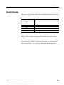
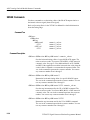
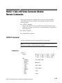
SENSE Commands
Use these queries to list which generator modules are using which frame reset
signals.
Command Tree
:SENSe
:ROSCillator
:FRAMe[3]
:CATalog?
:FREQuency?
Command Description
'!+ 34!+5(
Lists the modules using the frame reset signal <n>. The suffix
identifies which of three frame reset signals to query.
'!+ 34 D
7(
Lists the specific frame reset signal frequency.
TG700 TV Signal Generator Platform Programmer Manual
2- 21
TG700 Remote Commands
STATUS Commands
Use these commands to address the instrument status and event queue.
Command Tree
:STATus
:OPERation
[:EVENt]?
:CONDition?
:ENABle
:PTRansition
:NTRansition
:MAP
:INSTrument
[:EVENt]?
:CONDition?
:ENABle
:PTRansition
:NTRansition
:PRESet
:QUEue
[:NEXT]
:ENABle
:QUEStionable
[:EVENt]?
:CONDition?
:ENABle
:PTRansition
:NTRansition
:MAP
:INSTrument
[:EVENt]?
:CONDition?
:ENABle
:PTRansition
:NTRansition
2- 22
<numeric_value>
<numeric_value>
<numeric_value>
<numeric_value>, <numeric_value>
<numeric_value>
<numeric_value>
<numeric_value>
<numeric_value>
<numeric_value>
<numeric_value>
<numeric_value>, <numeric_value>
<numeric_value>
<numeric_value>
<numeric_value>
TG700 TV Signal Generator Platform Programmer Manual
TG700 Remote Commands
Command Description
PRESet. The OPERation node covers areas of instrument operational events. This
node reports such items as signal settling, calibration, or running a sequence
QUEStionable. The QUEStionable node covers areas of questionable conditions
that exist within the instrument. Questionable conditions might cause you to be
unsure of the quality of the generated signals.
Subnodes. Each node has a set of subnodes that query the contents, or control the
involvement, of each bit.
H
ENABle selects which bits are active in reporting the status.
H
EVENt is a destructive query only of the status.
H
CONDition is a nondesctructive query only of the status.
H
PTRansition allows a status to become true on a positive transition of the
event.
H
NTRansition allows a status to become true on a negative transition of the
event.
H
MAP reassigns event reporting at the top level of the status hierarchy.
H
INSTrument. Both main nodes have this sub node that summarizes the
operational and questionable condition of the instrument. Each bit in these
two registers represents a slot in the TG700. The summation of each register
will feed into bit 13 of its respective parent register.
PRESet. All of the enable registers are set to TRUE so that they return to
power-up conditions.
QUEue. QUEue:ENABle enables certain events or error conditions to be reported.
Values that are not explicitly specified are not reported. STATus:QUEue[:NEXT?] is the same as SYSTem:ERRor?.
Due to the repetitiveness of this subsystem, the details will be covered for the
nodes EVENt, CONDition, ENABle, PTRansition, NTRanstion, and MAP. The
syntax and examples do not include the full command. Refer to the Command
Tree to derive what commands would be appropriate. The following text then
describes each major branch within the STATus subsystem.
TG700 TV Signal Generator Platform Programmer Manual
2- 23
TG700 Remote Commands
<=(
Performs a destructive reading of the specific event status register.
The contents are cleared by reading or by *CLS.
''+(
Performs a nondestructive reading of the specified condition register.
Contents are cleared as a result of *CLS.
6
3
':;!
4
Sets the register that enables the individual bits within the Event
Register, which records event transition.
6
(
Returns the current Event Register settings.
!.''+ 3
':;!
4
Sets the transistion register for enabling events to set bits true during
a positive transition.
!.''+(
Returns the transistion register for enabling events to set bits true
during a positive transition.
!.''+ 3
':;!
4
Sets the transition register for enabling events to set bits true during
a negative transition.
!.''+(
Returns the transition register for enabling events to set bits true
during a negative transition.
.!'+ 3?'4A3
;
4
.D'+!?
3?'4A3
;
4
Reassigns events to bits in the OPERation or QUEStionable
registers.
2- 24
TG700 TV Signal Generator Platform Programmer Manual
TG700 Remote Commands
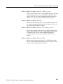
SYSTEM Commands
Use these commands to query the system related information and set the
front-panel lock function.
Command Tree
:SYSTem
:ERROR
[:NEXT]?
:HELP
:SYNTax?
:KLOCk
:STATe ON|OFF
:VERSion?
Command Description
@
+(
Lists the next event in the Error/Event queue. Queue is cleared at
power up, upon *CLS, and upon reading the last item.
@
@!-(
Lists correct command syntax.
@
8C
9
Locks or unlocks the front-panel buttons. You can use 1 or 0 instead
of ON or OFF.
@
8C
(
Returns the current status of the front-panel buttons.
@
'+(
Lists the SCPI compliance version. Query only.
TG700 TV Signal Generator Platform Programmer Manual
2- 25
TG700 Remote Commands
2- 26
TG700 TV Signal Generator Platform Programmer Manual
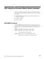
AG7 Audio Generator Module Remote Commands
This section describes the command sets used for the AG7 Generator module
remote operation. The commands for the module are divided into the following
groups:
H
OUTPUT commands
H
SENSE commands
OUTPUT Commands
Use these commands to set the parameters for each audio channel, the audio data
resolution, and the synchronization state relative to the frame reset signals.
Command Tree
'+
34
'>
D
7
C
6.
@/+'0
>
3
':;!
4
3
':;!
4
#9"9*9E9F
9 :9 :$
Command Description
'+
34'>
3
':;!
4
Sets the amplitude of a specific audio channel. The numeric value
can range from --60 dBFS to 0 dBFS in 1 dBFS steps. The <n> in
the command represents the channel number. You can use any
channel number from 1 through 8.
'+
34'>
(
Returns the amplitude of a specific audio channel. The <n> in the
command represents the channel number. You can use any channel
number from 1 through 8.
TG700 TV Signal Generator Platform Programmer Manual
2- 27
AG7 Audio Generator Module Remote Commands
'+
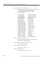
34 D
7 3
':;!
4
Sets the frequency of a specific audio channel. The unit is Hertz. The
choices are 0, 50, 100, 150, 200, 250, 300, 400, 500, 600, 750, 800,
1000, 1200, 1500, 1600, 2000, 2400, 3000, 3200, 4000, 4800, 5000,
6000, 8000, 9600, 10000, 12000, 15000, 16000, and 20000. The
<n> in the command represents the channel number. You can use
any channel number from 1 through 8.
'+
34 D
7(
Returns the frequency of a specific audio channel. The <n> in the
command represents the channel number. You can use any channel
number from 1 through 8.
'+
34C #9"9*9E9F
Sets the audio click of a specific audio channel. The choices are
1 sec to 4 sec, or 0. When 1 to 4 is selected, the audio click becomes
valid. When audio click is valid, audio tone is turned off for
0.25 seconds around the time of the click. The <n> in the command
represents the channel number. You can use any channel number
from 1 through 8.
'+
34C(
Returns the audio click setting for the specified audio channel. The
<n> in the command represents the channel number. You can use
any channel number from 1 through 8.
'+6. *#9*F
Sets the sample bits of the audio signal. The choices are 20 bits or
24 bits.
'+6.(
Returns the sample bits of the audio signal.
'+@/+'0
> 9 :9 :$
Selects the frame reset signal to synchronize with the audio signal.
The choices are FREErun (free run), FRAME_ONE (frame reset
signal 1), and FRAME_TWO (frame reset signal 2). For FREErun,
the audio signal is not synchronized with any of the frame reset
signals.
'+@/+'0
>(
Returns the frame reset signal synchronized with the audio signal.
2- 28
TG700 TV Signal Generator Platform Programmer Manual
AG7 Audio Generator Module Remote Commands
SENSE Commands
Use these commands to adjust the timing offset of the audio outputs relative to
the internal reference signal (frame reset signal).
Command Tree
'+
!7
3
':;!
4
3
':;!
4
Command Description
'+!7 3
':;!
4
Sets the timing offset of the audio outputs. The numeric values range
from --160 ms to 160 ms in 1 s steps. You can use UP, DOWN, or
DEF instead of the numeric values.
'+!7(
Returns the timing offset of the audio outputs.
'+!7 3
':;!
4
Sets the step increment used by the UP or DOWN commands. The
unit is microseconds.
'+!7(
Returns the step increment used by the UP or DOWN commands.
TG700 TV Signal Generator Platform Programmer Manual
2- 29
AG7 Audio Generator Module Remote Commands
2- 30
TG700 TV Signal Generator Platform Programmer Manual
AGL7 Analog Genlock Module Remote Commands
This section describes the commands used for the AGL7 Genlock module remote
operation. The commands for the module are divided into the following four
groups:
H
INPUT commands
H
SOURCE commands
H
OUTPUT commands
H
SENSE commands
INPUT Commands
Use these commands to set the input standard and input connector for the
genlock signal.
Command Tree
>!>
.(
@(
$
D
7(
.'+
6.96.9E"G9@9@9@
9$
!9&
!
*HII9EH#92H*%9"FHIG%9"%H#9#
!97
Command Description
>!> 6.96.9E"G9@9@9@
Selects the input standard expected at the REF connector. The
choices are NBURst (burst lock to NTSC black burst), PBURst
(burst lock to PAL black burst), N318M (burst lock to NTSC black
burst with 10 field ID), NSYNc (sync lock to NTSC black burst),
PSYNc (sync lock to PAL black burst), and HDSYnc (lock to
HDTV trilevel sync).
TG700 TV Signal Generator Platform Programmer Manual
2- 31
AGL7 Analog Genlock Module Remote Commands
>!>(
Returns the current input standard.
.(
Returns the current genlock status. The available responses are
INTernal, ABSent, UNLocked, or LOCKed.
@(
Returns the format of the HDTV trilevel sync signal currently
inputted. The available responses are HD1080_60I, HD1080_59I,
HD1080_50I, HD1080_24SF, HD1080_23SF, HD1080_30P,
HD1080_29P, HD1080_25P, HD1080_24P, HD1080_23P,
HD720_60P, HD720_59P or HD720_50P.
9$
Sets the reference input for the genlock source. For REF, a black
burst signal or HDTV trilevel signal applied to the REF connector is
used. For CW, a CW signal applied to the CW connector is used for
the genlock source.
(
Returns the reference input currently used.
!9&
!
Determines whether the internal signal or external signal is used as a
reference signal.
(
Returns the signal source (internal or external) used as a reference
signal.
$
*HII9EH#92H*%9"FHIG%9"%H#9#
Sets the frame reset signal frequency used when a CW signal is
applied to the CW connector. The choices are 2.997 Hz, 3.0 Hz,
6.25 Hz, 14.985 Hz, and 15.0 Hz. For 0, the instrument is set to
Keep Composite Timing.
$
(
Returns the current frequency of the frame reset signal for the CW
input.
2- 32
TG700 TV Signal Generator Platform Programmer Manual
AGL7 Analog Genlock Module Remote Commands
$
D
7(
Returns the frequency of the CW signal currently applied. The
available responses are 1.0, 3.58, 4.43, 5.0, or 10.0.
.'+ !97
Sets the instrument action when a loss of genlock state occurs. For
INTernal, the instrument automatically switches to the internal
reference. For STAy, the instrument maintains the current state.
.'+(
Returns the current instrument action when a loss of genlock state
occurs. The available responses are INT or STA.
SOURCE Commands
Use these commands to set the timing offset of the genlock input signal relative
to the internal reference signal (frame reset signal).
Refer to Operating Basics in the TG700 User Manual for detailed information
about the setting range.
Command Tree
'+
!7
'0+!
'!
3
':;!
4
3
':;!
4
3
':;!
4
3
':;!
4
Command Description
'+!7'0+! 3
':;!
4
Sets the horizontal timing offset of the genlock input signal relative
to the internal reference signal. The units are microseconds. You can
use UP, DOWN, or DEF instead of a numeric value.
'+!7'0+!(
Returns the horizontal timing offset of the genlock input signal.
TG700 TV Signal Generator Platform Programmer Manual
2- 33
AGL7 Analog Genlock Module Remote Commands
'+!7'0+! 3
':;!
4
Sets the step increment used by the UP or DOWN command. The
units are microseconds. You can use MIN, MAX, or DEF instead of
a numeric value.
'+!7'0+!(
Returns the step increment used by the UP or DOWN command.
'+!7'! 3
':;!
4
Sets the vertical timing offset of the genlock input signal relative to
the internal reference signal. The units are line numbers. You can
use UP, DOWN, or DEF instead of a numeric value.
'+!7'!(
Returns the vertical timing offset of the genlock input signal.
'+!7'! 3
':;!
4
Sets the step increment used by the UP or DOWN command. The
units are line numbers. You can use MIN, MAX, or DEF instead of a
numeric value.
'+!7'!(
Returns the step increment used by the UP or DOWN command.
OUTPUT Commands
Use these commands to set the video standard and the type of signal for the
BLACK outputs.
Command Tree
"
>!>
*
>!>
E
>!>
34
!
2- 34
99:
99:9@
669"#G#:2#9"#G#:%I9"#G#:%#9
"#G#:*F 9"#G#:E#9"#G#:*I9
"#G#:*%9"#G#:*F9"#G#:*E9
*#:2#9*#:%I9*#:%#
66966: 966:: TG700 TV Signal Generator Platform Programmer Manual
AGL7 Analog Genlock Module Remote Commands
Command Description
">!> 99:
Sets the video standard for the BLACK 1 output. The choices are
NTSC, PAL, and NTSC_NSU (NTSC no setup).
">!>(
Returns the video standard for the BLACK 1 output.
*>!> 99:9@
Sets the video standard for the BLACK 2 output. The choices are
NTSC, PAL, NTSC_NSU (NTSC no setup), and HDSYnc (HDTV
trilevel sync).
*>!>(
Returns the video standard for the BLACK 2 output.
E>!> 669"#G#:2#9"#G#:%I9"#G#:%#9
"#G#:*F 9"#G#:E#9"#G#:*I9
"#G#:*%9"#G#:*F9"#G#:*E9
*#:2#9*#:%I9*#:%#
Sets the video standard for the BLACK 3 output. The choices are
BB (black burst) and HD1080_60I to HD720_50P.
E>!>(
Returns the video standard for the BLACK 3 output.
34! 66966: 966:: Sets what kind of signal is available from a specific BLACK output.
The <n> in the command represents the connector number. You can
use connector number 1 and 2.
If the standard is NTSC or NTSC_NSU, the options are BB (black
burst) or BB_FREF (black burst with field reference).
If the standard is PAL, the options are BB (black burst) or
BB_NO_FREF (black burst no field reference).
34!(
Returns the current output signal. The <n> in the command
represents the connector number. You can use connector number 1
and 2.
TG700 TV Signal Generator Platform Programmer Manual
2- 35
AGL7 Analog Genlock Module Remote Commands
SENSE Commands
Use these commands to set the timing offset of the BLACK outputs relative to
the internal reference signal (frame reset signal).
Refer to Operating Basics in the TG700 User Manual for detailed information
about the setting range.
Command Tree
34
'+
!7
'0+!
'!
3
':;!
4
3
':;!
4
3
':;!
4
3
':;!
4
Command Description
34
'+!7'0+! 3
':;!
4
Sets the horizontal timing offset of a specific BLACK output. The
units are microseconds. You can use UP, DOWN, or DEF instead of
a numeric value. See page 2--2 for additional detail on UP, DOWN,
and DEF. If the argument exceeds the horizontal time value, then the
vertical offset is adjusted to accommodate the requested offset. The
<n> in the command represents the connector number. You can use
any connector number from 1 through 3.
34
'+!7'0+!(
Returns the horizontal timing offset of a specific BLACK output.
The <n> in the command represents the connector number. You can
use any connector number from 1 through 3.
34
'+!7'0+! 3
':;!
4
Sets the step increment used by the UP or DOWN command. The
units are microseconds. You can use MIN, MAX, or DEF instead of
a numeric value. The <n> in the command represents the connector
number. You can use any connector number from 1 through 3.
34
'+!7'0+!(
Returns the step increment used by the UP or DOWN command.
The <n> in the command represents the connector number. You can
use any connector number from 1 through 3.
2- 36
TG700 TV Signal Generator Platform Programmer Manual
AGL7 Analog Genlock Module Remote Commands
34
'+!7'! 3
':;!
4
Sets the vertical timing offset of a specific BLACK output. The units
are horizontal lines. You can use UP, DOWN, or DEF instead of a
numeric value. The <n> in the command represents the connector
number. You can use any connector number from 1 through 3.
34
'+!7'!(
Returns the vertical timing offset of a specific BLACK output. The
<n> in the command represents the connector number. You can use
any connector number from 1 through 3.
34
'+!7'! 3
':;!
4
Sets the step increment used by the UP or DOWN commands. The
units are horizontal lines. You can use MIN, MAX, or DEF instead
of a numeric value. The <n> in the command represents the
connector number. You can use any connector number from 1
through 3.
34
'+!7'!(
Returns the step increment used by the UP or DOWN commands.
The <n> in the command represents the connector number. You can
use any connector number from 1 through 3.
TG700 TV Signal Generator Platform Programmer Manual
2- 37
AGL7 Analog Genlock Module Remote Commands
2- 38
TG700 TV Signal Generator Platform Programmer Manual
ATG7 Analog Test Generator Module Remote Commands
This section describes the command sets used for the ATG7 Generator module
remote operation. The commands for the module are divided into the following
three groups:
H
MASS MEMORY commands ( Refer to the TG700 TV Signal Generator
Platform User Manual)
H
OUTPUT commands
H
SENSE commands
MASS MEMORY Commands
Two MASS MEMORY commands are listed here for your reference. You can
use these to load and query the output test signal. Detailed information for using
these commands are located in the TG700 TV Signal Generator Platform User
Manual.
+7! 3+>
:!
4A3.'5!:!
4
+7! 3.+:?
4A3.'5!:!
4
Loads a signal into the specified module.
+7!';
( 3.+:?
493+>
:!
4
Returns the current output signal of the specified module.
TG700 TV Signal Generator Platform Programmer Manual
2- 39
ATG7 Analog Test Generator Module Remote Commands
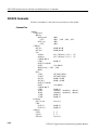
OUTPUT Commands
Use these commands to control the output parameters of the module. These
include ID text overlay and APL features.
Command Tree
34
>!>
!
9:9
66966: 966:: 9@9689
69:9:9 9
: JK"A*L
!7
6C
'+>
&
''+
'0+!
'!
'+>
66966:: 96"##:96%:9
6:9 F#96"##:96%:9
:9:$ JKFL
9
3
':;!
4
9
3.'54
3
':;!
4
3
':;!
4
: 9:9:$9:6
3
':;!
4
Command Description
34>!> 9:9
Sets the video standard for the BLACK 1, BLACK 2, or BARS
output. The choices are NTSC, NTSC_NSU (NTSC no setup), or
PAL. The <n> in the command represents the output connector type
and you can specify 1, 2, or 4. “1” represents the BLACK 1
connector, “2” represents the BLACK 2 connector, and “4”
represents the BARS connector.
2- 40
TG700 TV Signal Generator Platform Programmer Manual
ATG7 Analog Test Generator Module Remote Commands
34>!>(
Returns the video standard for the BLACK 1, BLACK 2, or BARS
output. The <n> in the command represents the output connector and
you can specify 1, 2, or 4. “1” represents the BLACK 1 connector,
“2” represents the BLACK 2 connector, and “4” represents the
BARS connector.
34! 66966: 966:: 9@9689
69:9:9 9
: JK"A*L
66966:: 96"##:96%:96:9
F#96"##:96%:9:9
:$ JKFL
Sets the signal available from the BLACK 1, BLACK 2, or BARS
output. The <n> in the command represents the output connector and
you can specify 1, 2, or 4. “1” represents the BLACK 1 connector,
“2” represents the BLACK 2 connector, and “4” represents the
BARS connector.
If “1” or “2” is specified for the connector type, the choices are BB
(black burst), BB_FREF (black burst with field reference),
BB_NO_FREF (black burst no field reference), SYNC (composite
sync), BLANKING (composite blanking), SUBCARRIER (subcarrier), H_DRIVE (H drive), V_DRIVE (V drive), FREF (Color Frame
ID), or PAL PULSE (PAL pulse).
If “4” is specified for the connector type, the choices are BB (black
burst), BB_FREF (black burst with field reference), BB_NO_FREF
(black burst no field reference), CB100PER (100% color (or colour)
bars), CB75PER (75% color (or colour) bars), CB_100_OR (100%
colour bars over red), CB_75_OR (75% colour bars over red),
CB_SMPTE (SMPTE color bars), FF40PER (40% flat field),
OTHER_ONE (Other 1), or OTHER_TWO (Other 2).
34!(
Returns the current output signal for the BLACK 1, BLACK 2, or
BARS output. The <n> in the command represents the output
connector and you can specify 1, 2, or 4. “1” represents the BLACK
1 connector, “2” represents the BLACK 2 connector, and “4”
represents the BARS connector.
34!76C
9
Turns the text blinking mode on or off. You can also use 1 or 0
instead of ON or OFF. The <n> in the command represents the
output connector and you can specify 3 or 4. “3” represents the
SIGNAL connector and “4” represents the BARS connector.
TG700 TV Signal Generator Platform Programmer Manual
2- 41
ATG7 Analog Test Generator Module Remote Commands
34!76C
(
Returns the current state of the text blinking mode. The <n> in the
command represents the output connector and you can specify 3 or
4. “3” represents the SIGNAL connector and “4” represents the
BARS connector.
34!76C'+> 3
':;!
4
Sets the blinking interval of the text blinking mode. You can set the
value as 0.5 seconds or 1.0 seconds. The <n> in the command
represents the output connector and you can specify 3 or 4. “3”
represents the SIGNAL connector and “4” represents the BARS
connector.
34!76C'+>(
Returns the blinking interval of the text blinking mode. The <n> in
the command represents the output connector and you can specify 3
or 4. “3” represents the SIGNAL connector and “4” represents the
BARS connector.
34&
9
Turns the text overlay on the video signal on or off. You can also use
1 or 0 instead of ON or OFF. The <n> in the command represents
the output connector and you can specify 3 or 4. “3” represents the
SIGNAL connector and “4” represents the BARS connector.
34&
(
Returns the current text overlay state. The <n> in the command
represents the output connector and you can specify 3 or 4. “3”
represents the SIGNAL connector and “4” represents the BARS
connector.
34& 3.'54
Sets the current string for the text overlay mode. The <n> in the
command represents the output connector and you can specify 3 or
4. “3” represents the SIGNAL connector and “4” represents the
BARS connector. The text string may contain up to 18 characters.
34&(
Returns the current string for the text overlay mode. The <n> in the
command represents the output connector and you can specify 3 or
4. “3” represents the SIGNAL connector and “4” represents the
BARS connector.
2- 42
TG700 TV Signal Generator Platform Programmer Manual
ATG7 Analog Test Generator Module Remote Commands
34&''+'0+! 3
':;!
4
Sets the text horizontal position in the video signal. The unit is
percent of active picture width. You can set the position from 0% to
100% in 1% steps. You can also use MIN, MAX, or DEF instead of
the numeric value. The <n> in the command represents the output
connector and you can specify 3 or 4. “3” represents the SIGNAL
connector and “4” represents the BARS connector.
34&''+'0+!(
Returns the current text horizontal position in the video signal. The
<n> in the command represents the output connector and you can
specify 3 or 4. “3” represents the SIGNAL connector and “4”
represents the BARS connector.
34&''+'! 3
':;!
4
Sets the text vertical position in the video signal. The unit is percent
of active picture height. You can set the position from 0% to 100%
in 1% steps. You can also use MIN, MAX, or DEF instead of the
numeric value. The <n> in the command represents the output
connector and you can specify 3 or 4. “3” represents the SIGNAL
connector and “4” represents the BARS connector.
34&''+'!(
Returns the current text vertical position in the video signal. The
<n> in the command represents the output connector and you can
specify 3 or 4. “3” represents the SIGNAL connector and “4”
represents the BARS connector.
34&
Saves the current text and its display position to the signal file.
There are no arguments. The <n> in the command represents the
output connector and you can specify 3 or 4. “3” represents the
SIGNAL connector and “4” represents the BARS connector.
34
: 9:9:$9:696
Sets the output mode of the APL signal. Refer to Operating Basics
in the TG700 User Manual for detailed information about each
mode. You can only specify “3” (SIGNAL connector) for the <n>.
34
(
Returns the current output mode of the APL signal. You can specify
only “3” (SIGNAL connector) for the <n>.
TG700 TV Signal Generator Platform Programmer Manual
2- 43
ATG7 Analog Test Generator Module Remote Commands
34'+> 3
':;!
4
Sets the time interval between two signals when they are output in
the bounce modes. You can set the value from 0.5 seconds to
2.0 seconds in 0.5 seconds steps. You can specify only “3” (SIGNAL
connector) for the <n>.
34'+>(
Returns the time interval between two signals when they are output
in the bounce modes. You can specify only “3” (SIGNAL connector)
for the <n>.
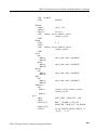
SENSE Commands
Use these commands to adjust the timing offset of each output relative to the
internal reference signal (frame reset signal).
Refer to Operating Basics in the TG700 User Manual for detailed information
about the timing offset range.
Command Tree
34
'+
!7
'0+!
'!
3
':;!
4
3
':;!
4
3
':;!
4
3
':;!
4
Command Description
34
'+!7'0+! 3
':;!
4
Sets the horizontal timing offset for the specified output. The timing
resolution is clock-cycles. The unit is microseconds. You can use
UP, DOWN, or DEF instead of the numeric values. See page 2--2 for
additional detail on UP, DOWN, and DEF. If the argument exceeds
the horizontal time value, then the vertical offset is adjusted to
accommodate the requested offset. The <n> in the command
represents the output connector and you can specify from 1 through
4. “1” represents the BLACK 1 connector, “2” represents the
BLACK 2 connector, “3” represents the SIGNAL connector, and “4”
represents the BARS connector.
2- 44
TG700 TV Signal Generator Platform Programmer Manual
ATG7 Analog Test Generator Module Remote Commands
34
'+!7'0+!(
Returns the horizontal timing offset of the specified output. The <n>
in the command represents the output connector and you can specify
from 1 through 4. “1” represents the BLACK 1 connector, “2”
represents the BLACK 2 connector, “3” represents the SIGNAL
connector, and “4” represents the BARS connector.
34
'+!7'0+! 3
':;!
4
Sets the step increment used by the UP or DOWN commands. The
unit is microseconds. You can use UP, DOWN, or DEF instead of
the numeric values. The <n> in the command represents the output
connector and you can specify from 1 through 4. “1” represents the
BLACK 1 connector, “2” represents the BLACK 2 connector, “3”
represents the SIGNAL connector, and “4” represents the BARS
connector.
34
'+!7'0+!(
Returns the step increment used by the UP or DOWN commands.
The <n> in the command represents the output connector and you
can specify from 1 through 4. “1” represents the BLACK 1
connector, “2” represents the BLACK 2 connector, “3” represents the
SIGNAL connector, and “4” represents the BARS connector.
34
'+!7'! 3
':;!
4
Sets the vertical timing offset of the specified output. The argument
can be a floating point value that is translated into integer lines with
a horizontal offset. You can use UP, DOWN, or DEF instead of a
numeric value. The <n> in the command represents the output
connector and you can specify from 1 through 4. “1” represents the
BLACK 1 connector, “2” represents the BLACK 2 connector, “3”
represents the SIGNAL connector, and “4” represents the BARS
connector.
34
'+!7'!(
Returns the vertical timing offset of the specified output. The <n> in
the command represents the output connector and you can specify
from 1 through 4. “1” represents the BLACK 1 connector, “2”
represents the BLACK 2 connector, “3” represents the SIGNAL
connector, and “4” represents the BARS connector.
TG700 TV Signal Generator Platform Programmer Manual
2- 45
ATG7 Analog Test Generator Module Remote Commands
34
'+!7'! 3
':;!
4
Sets the step increment used by the UP or DOWN commands. You
can use MIN, MAX, or DEF instead of the numeric values. The <n>
in the command represents the output connector and you can specify
from 1 through 4. “1” represents the BLACK 1 connector, “2”
represents the BLACK 2 connector, “3” represents the SIGNAL
connector, and “4” represents the BARS connector.
34
'+!7'!(
Returns the step increment used by the UP or DOWN commands.
The <n> in the command represents the output connector and you
can specify from 1 through 4. “1” represents the BLACK 1
connector, “2” represents the BLACK 2 connector, “3” represents the
SIGNAL connector, and “4” represents the BARS connector.
2- 46
TG700 TV Signal Generator Platform Programmer Manual
AVG7 Analog Video Generator Module Remote Commands
This section describes the remote commands used to control the AVG7 Generator
module remotely. The commands to the module are divided into the following
three groups:
H
MASS MEMORY commands (Refer to the TG700 TV Signal Generator
Platform User Manual)
H
OUTPUT commands
H
SENSE commands
MASS MEMORY Commands
Two MASS MEMORY commands are listed here for your reference. You can
use these to load and query the output test signal. Detailed information for using
these commands are located in the TG700 TV Signal Generator Platform User
Manual.
+7! 3+>
:!
4A3.'5!:!
4
+7! 3.+:?
4A3.'5!:!
4
Loads a signal into the specified module.
+7!';
( 3.+:?
493+>
:!
4
Returns the current output signal of the specified module.
TG700 TV Signal Generator Platform Programmer Manual
2- 47
AVG7 Analog Video Generator Module Remote Commands
OUTPUT Commands
Use these commands to control the output parameters of the module. These
include output status and circle/text/logo overlay.
Command Tree
34
''+
'0+!
'!
''+
'0+!
'!
&
''+
'0+!
'!
!7
6C
'+>
'+>
'0+!
'!
'+>
+<
=
+
'5
@
2- 48
9
9
3
':;!
4
3
':;!
4
3
':;!
4
9
3
':;!
4
3
':;!
4
3+5+:!
4
9
3.'54
3
':;!
4
3
':;!
4
9
3
':;!
4
: 9:9:$9:6
3
':;!
4
3
':;!
4
3
':;!
4
3
':;!
4
9
@9
3
':;!
4
9
TG700 TV Signal Generator Platform Programmer Manual
AVG7 Analog Video Generator Module Remote Commands
Command Description
34
9
Turns the signal output of the specified channel on or off. The <n>
in the command represents the output channel and you can specify 1,
2, or 3. You can use 1 or 0 instead of ON or OFF.
34
(
Returns the current output state of the specified channel. The <n> in
the command represents the output channel and you can specify 1, 2,
or 3.
"
9
Turns the circle overlay on the video signal on or off. You can use 1
or 0 instead of ON or OFF.
"
(
Returns the current circle overlay state.
"
3
':;!
4
Sets the diameter of the displayed circle. The unit is the percent of
active picture height. You can set the diameter from 0% to 100% in
1% steps. You can also use MIN, MAX, or DEF instead of a
numeric value.
"
(
Returns the diameter of the displayed circle.
"
''+'0+! 3
':;!
4
Sets the horizontal position of the circle as it appears on the active
signal. The unit is the percent of active picture width. You can set
the position from --50% to +50% in 1% steps. You can also use
MIN, MAX, or DEF instead of a numeric value.
"
''+'0+!(
Returns the current horizontal position of the circle as it appears on
the active signal.
"
''+'! 3
':;!
4
Sets the vertical position of the circle as it appears on the active
signal. The unit is the percent of active picture height. You can set
the position from --50% to +50% in 1% steps. You can also use
MIN, MAX, or DEF instead of a numeric value.
TG700 TV Signal Generator Platform Programmer Manual
2- 49
AVG7 Analog Video Generator Module Remote Commands
"
''+'!(
Returns the current vertical position of the circle as it appears on the
active signal.
"
9
Turns the logo overlay on the video signal on or off. You can use 1
or 0 instead of ON or OFF.
"
(
Returns the current logo overlay state.
"''+'0+! 3
':;!
4
Sets the horizontal position of the logo as it appears on the active
signal. The unit is the percent of active picture width. You can set
the position from --100% to 0% in 0.1% steps. You can also use
MIN, MAX, or DEF instead of a numeric value.
"''+'0+!(
Returns the current horizontal position of the logo.
"''+'! 3
':;!
4
Sets the vertical position of the logo as it appears on the active
signal. The unit is the percent of active picture height. You can set
the position from --100% to 0% in 0.1% steps. You can also use
MIN, MAX, or DEF instead of a numeric value.
"''+'!(
Returns the current vertical position of the logo.
"
3+5+:!
4
Selects the logo used for the logo overlay.
"
(
Returns the current logo used for the logo overlay.
"
Saves the current display position of the logo to the logo file. There
are no arguments.
"&
9
Turns the text overlay on the video signal on or off. You can use 1 or
0 instead of ON or OFF.
2- 50
TG700 TV Signal Generator Platform Programmer Manual
AVG7 Analog Video Generator Module Remote Commands
"&
(
Returns the current text overlay state.
"& 3.'54
Sets the current string for the text mode.
"&(
Returns the current string for the text mode.
"&''+'0+! 3
':;!
4
Sets the text horizontal position in the video signal. The unit is the
percent of active picture width. You can set the position from 0% to
100% in 1% steps. You can also use MIN, MAX, or DEF instead of
the numeric value.
"&''+'0+!(
Returns the current text horizontal position in the video signal.
"&''+'! 3
':;!
4
Sets the text vertical position in the video signal. The unit is the
percent of active picture height. You can set the position from 0.0%
to 100.0% in 1% steps. You can also use MIN, MAX, or DEF
instead of the numeric value.
"&''+'!(
Returns the current text vertical position in the video signal.
"&
Saves the current text and its display position to the signal file.
There are no arguments.
"!76C
9
Turns on or off the blinking mode for the logo, text, and circle
overlay. You can also use 1 or 0 instead of ON or OFF
"!76C
(
Returns the current state of the blinking mode for the logo, text, and
circle overlay.
"!76C'+> 3
':;!
4
Sets the blinking interval of the blinking mode for the logo, text, and
circle overlay. You can set the value as 0.5 seconds or 1.0 seconds.
TG700 TV Signal Generator Platform Programmer Manual
2- 51
AVG7 Analog Video Generator Module Remote Commands
"!76C'+>(
Returns the blinking interval of the blinking mode for the logo, text,
and circle overlay.
"
: 9:9:$9:696
Sets the output mode of the APL signal. Refer to the APL Submenu
section in the TG700 User Manual for detailed information about the
each mode.
"
(
Returns the current output mode of the APL signal.
"'+> 3
':;!
4
Sets the time interval between two signals when they are output in
the bounce modes. You can set the value from 0.5 seconds to
2.0 seconds in 0.5 seconds steps.
"'+>(
Returns the time interval between two signals when they are output
in the bounce modes.
"
'0+! 3
':;!
4
Sets the amount of horizontal scrolling in the moving picture mode.
You can set the value from --252 to +252 in 4 samples steps.
"
'0+!(
Returns the amount of horizontal scrolling in the moving picture
mode.
"
'! 3
':;!
4
Sets the amount of vertical scrolling in the moving picture mode.
You can set the value from --252 to +252 in 1 line steps.
"
'!(
Returns the amount of vertical scrolling in the moving picture mode.
"
'+> 3
':;!
4
Sets the time interval between occurrences of the scrolling. You can
set the value from 1 to 16 in 1 field steps.
"
'+>(
Returns the time interval between occurrences of the scrolling.
2- 52
TG700 TV Signal Generator Platform Programmer Manual
AVG7 Analog Video Generator Module Remote Commands
"
+
9
Turns the random scrolling mode on or off. You can also use 1 or 0
instead of ON or OFF.
"
+
(
Returns the current state of the random scrolling mode.
"
+ '5 @9
Sets the output channel configuration when a composite signal is
being output. For YC, a Y signal, C signal, and composite signal
will be assigned to CH1, CH2, and CH3 respectively. For COMPOSITE, a composite signal will be assigned to all the three
channels.
"
+ '5(
Returns the current setting of the output channel configuration when
a composite signal is being output.
"
+ 3
':;!
4
Sets the SCH phase for a composite signal. You can set the value
from --180 degrees to +180 degrees in 1 degree steps.
"
+(
Returns the current SCHphase setting.
"
+@
9
Sets whether or not a sync signal is multiplexed with the B and R
signals when a GBR signal is being output. You can also use 1 or 0
instead of ON or OFF.
"
+@
(
Returns whether or not a sync signal is multiplexed with the B and R
signals when a GBR signal is being output.
TG700 TV Signal Generator Platform Programmer Manual
2- 53
AVG7 Analog Video Generator Module Remote Commands
SENSE Commands
Use these commands to set the timing offset of the output signals relative to the
internal reference signal (frame reset signal).
Refer to Operating Basics in the TG700 User Manual for detailed information
about the setting range.
Command Tree
34
'+
!7
'0+!
'!
3
':;!
4
3
':;!
4
3
':;!
4
3
':;!
4
Command Description
"
'+!7'0+! 3
':;!
4
Sets the horizontal timing offset of the output signals. The timing
resolution is clock-cycles. The units are microseconds. You can use
UP, DOWN, or DEF instead of the numeric value. If the argument
exceeds the horizontal time value, then the vertical offset is adjusted
to accommodate the requested delay.
"
'+!7'0+!(
Returns the current horizontal timing offset of the output signals.
"
'+!7'0+! 3
':;!
4
Sets the step increment used by the UP or DOWN commands. The
units are microseconds. You can use MIN, MAX, or DEF instead of
a numeric value.
"
'+!7'0+!(
Returns the current step increment.
"
'+!7'! 3
':;!
4
Sets the vertical timing offset of the output signals. The argument
can be a floating point value that is translated into integer lines with
a horizontal offset. You can use UP, DOWN, or DEF instead of a
numeric value.
2- 54
TG700 TV Signal Generator Platform Programmer Manual
AVG7 Analog Video Generator Module Remote Commands
"
'+!7'!(
Returns the current vertical timing offset of the output signals.
"
'+!7'! 3
':;!
4
Sets the step increment used by the UP or DOWN commands. You
can use MIN, MAX, or DEF instead of a numeric value.
"
'+!7'!(
Returns the current step increment.
TG700 TV Signal Generator Platform Programmer Manual
2- 55
AVG7 Analog Video Generator Module Remote Commands
2- 56
TG700 TV Signal Generator Platform Programmer Manual
AWVG7 Analog Wideband Video Generator Module
Remote Commands
This section describes the remote commands used to control the AWVG7
Generator module remotely. The commands to the module are divided into the
following three groups:
H
MASS MEMORY commands (Refer to the TG700 TV Signal Generator
Platform User Manual)
H
OUTPUT commands
H
SENSE commands
MASS MEMORY Commands
Two MASS MEMORY commands are listed here for your reference. You can
use these to load and query the output test signal. Detailed information for using
these commands are located in the TG700 TV Signal Generator Platform User
Manual.
+7! 3+>
:!
4A3.'5!:!
4
+7! 3.+:?
4A3.'5!:!
4
Loads a signal into the specified module.
+7!';
( 3.+:?
493+>
:!
4
Returns the current output signal of the specified module.
TG700 TV Signal Generator Platform Programmer Manual
2- 57
AWVG7 Analog Wideband Video Generator Module Remote Commands
OUTPUT Commands
Use these commands to control the output parameters of the module. These
include output status and circle/text/logo overlay.
Command Tree
34
''+
'0+!
'!
''+
'0+!
'!
&
''+
'0+!
'!
!7
6C
'+>
'0+!
'!
'+>
+<
=
+
@
2- 58
9
9
3
':;!
4
3
':;!
4
3
':;!
4
9
3
':;!
4
3
':;!
4
3+5+:!
4
9
3.'54
3
':;!
4
3
':;!
4
9
3
':;!
4
3
':;!
4
3
':;!
4
3
':;!
4
9
9
TG700 TV Signal Generator Platform Programmer Manual
AWVG7 Analog Wideband Video Generator Module Remote Commands
Command Description
34
9
Turns the signal output of the specified channel on or off. The <n>
in the command represents the output channel and you can specify 1,
2, or 3. You can use 1 or 0 instead of ON or OFF.
34
(
Returns the current output state of the specified channel. The <n> in
the command represents the output channel and you can specify 1, 2,
or 3.
"
9
Turns the circle overlay on the video signal on or off. You can use 1
or 0 instead of ON or OFF.
"
(
Returns the current circle overlay state.
"
3
':;!
4
Sets the diameter of the displayed circle. The unit is the percent of
active picture height. You can set the diameter from 0% to 100% in
1% steps. You can also use MIN, MAX, or DEF instead of a
numeric value.
"
(
Returns the diameter of the displayed circle.
"
''+'0+! 3
':;!
4
Sets the horizontal position of the circle as it appears on the active
signal. The unit is the percent of active picture width. You can set
the position from --50% to +50% in 1% steps. You can also use
MIN, MAX, or DEF instead of a numeric value.
"
''+'0+!(
Returns the current horizontal position of the circle as it appears on
the active signal.
"
''+'! 3
':;!
4
Sets the vertical position of the circle as it appears on the active
signal. The unit is the percent of active picture height. You can set
the position from --50% to +50% in 1% steps. You can also use
MIN, MAX, or DEF instead of a numeric value.
TG700 TV Signal Generator Platform Programmer Manual
2- 59
AWVG7 Analog Wideband Video Generator Module Remote Commands
"
''+'!(
Returns the current vertical position of the circle as it appears on the
active signal.
"
9
Turns the logo overlay on the video signal on or off. You can use 1
or 0 instead of ON or OFF.
"
(
Returns the current logo overlay state.
"''+'0+! 3
':;!
4
Sets the horizontal position of the logo as it appears on the active
signal. The unit is the percent of active picture width. You can set
the position from --100% to 0% in 0.1% steps. You can also use
MIN, MAX, or DEF instead of a numeric value.
"''+'0+!(
Returns the current horizontal position of the logo.
"''+'! 3
':;!
4
Sets the vertical position of the logo as it appears on the active
signal. The unit is the percent of active picture height. You can set
the position from --100% to 0% in 0.1% steps. You can also use
MIN, MAX, or DEF instead of a numeric value.
"''+'!(
Returns the current vertical position of the logo.
"
3+5+:!
4
Selects the logo used for the logo overlay.
"
(
Returns the current logo used for the logo overlay.
"
Saves the current display position of the logo to the logo file. There
are no arguments.
"&
9
Turns the text overlay on the video signal on or off. You can use 1 or
0 instead of ON or OFF.
2- 60
TG700 TV Signal Generator Platform Programmer Manual
AWVG7 Analog Wideband Video Generator Module Remote Commands
"&
(
Returns the current text overlay state.
"& 3.'54
Sets the current string for the text mode.
"&(
Returns the current string for the text mode.
"&''+'0+! 3
':;!
4
Sets the text horizontal position in the video signal. The unit is the
percent of active picture width. You can set the position from 0% to
100% in 1% steps. You can also use MIN, MAX, or DEF instead of
the numeric value.
"&''+'0+!(
Returns the current text horizontal position in the video signal.
"&''+'! 3
':;!
4
Sets the text vertical position in the video signal. The unit is the
percent of active picture height. You can set the position from 0% to
100% in 1% steps. You can also use MIN, MAX, or DEF instead of
the numeric value.
"&''+'!(
Returns the current text vertical position in the video signal.
"&
Saves the current text and its display position to the signal file.
There are no arguments.
"!76C
9
Turns on or off the blinking mode for the logo, text, and circle
overlay. You can also use 1 or 0 instead of ON or OFF.
"!76C
(
Returns the current state of the blinking mode for the logo, text, and
circle overlay.
"!76C'+> 3
':;!
4
Sets the blinking interval of the blinking mode for the logo, text, and
circle overlay. You can set the value as 0.5 seconds or 1.0 seconds.
TG700 TV Signal Generator Platform Programmer Manual
2- 61
AWVG7 Analog Wideband Video Generator Module Remote Commands
"!76C'+>(
Returns the blinking interval of the blinking mode for the logo, text,
and circle overlay.
"
'0+! 3
':;!
4
Sets the amount of horizontal scrolling in the moving picture mode.
You can set the value from --252 to +252 in 4 samples steps.
"
'0+!(
Returns the amount of horizontal scrolling in the moving picture
mode.
"
'! 3
':;!
4
Sets the amount of vertical scrolling in the moving picture mode.
You can set the value from --252 to +252 in 1 line steps.
"
'!(
Returns the amount of vertical scrolling in the moving picture mode.
"
'+> 3
':;!
4
Sets the time interval between occurrences of the scrolling. You can
set the value from 1 to 16 in 1 field steps.
"
'+>(
Returns the time interval between occurrences of the scrolling.
"
+
9
Turns the random scrolling mode on or off. You can also use 1 or 0
instead of ON or OFF.
"
+
(
Returns the current state of the random scrolling mode.
"
+@
9
Sets whether or not a sync signal is multiplexed with the B and R
signals when a GBR signal is being output. You can also use 1 or 0
instead of ON or OFF.
"
+@
(
Returns whether or not a sync signal is multiplexed with the B and R
signals when a GBR signal is being output.
2- 62
TG700 TV Signal Generator Platform Programmer Manual
AWVG7 Analog Wideband Video Generator Module Remote Commands
SENSE Commands
Use these commands to set the timing offset of the output signals relative to the
internal reference signal (frame reset signal).
Refer to Operating Basics in the TG700 User Manual for detailed information
about the setting range.
Command Tree
34
'+
!7
'0+!
'!
3
':;!
4
3
':;!
4
3
':;!
4
3
':;!
4
Command Description
"
'+!7'0+! 3
':;!
4
Sets the horizontal timing offset of the output signals. The timing
resolution is clock-cycles. The units are microseconds. You can use
UP, DOWN, or DEF instead of the numeric value. See page 2--2 for
additional detail on UP, DOWN, and DEF. If the argument exceeds
the horizontal time value, then the vertical offset is adjusted to
accommodate the requested delay.
"
'+!7'0+!(
Returns the current horizontal timing offset of the output signals.
"
'+!7'0+! 3
':;!
4
Sets the step increment used by the UP or DOWN commands. The
units are microseconds. You can use MIN, MAX, or DEF instead of
a numeric value.
"
'+!7'0+!(
Returns the current step increment.
"
'+!7'! 3
':;!
4
Sets the vertical timing offset of the output signals. The argument
can be a floating point value that is translated into integer lines with
a horizontal offset. You can use UP, DOWN, or DEF instead of a
numeric value.
TG700 TV Signal Generator Platform Programmer Manual
2- 63
AWVG7 Analog Wideband Video Generator Module Remote Commands
"
'+!7'!(
Returns the current vertical timing offset of the output signals.
"
'+!7'! 3
':;!
4
Sets the step increment used by the UP or DOWN commands. You
can use MIN, MAX, or DEF instead of a numeric value.
"
'+!7'!(
Returns the current step increment.
2- 64
TG700 TV Signal Generator Platform Programmer Manual
BG7 Black Generator Module Remote Commands
This section describes the command sets used for the BG7 Generator module
remote operation. The commands for the module are divided into the following
groups:
H
OUTPUT commands
H
SENSE commands
OUTPUT Commands
Use these commands to set the video standard and the kind of signal for the
BLACK outputs.
NOTE. Use of the OUTPUT4:TIMEcode commands requires hardware version
1.2 or later and software version 5.1 or later.
Command Tree
'5
(
34
>!>
F
+>
.(
(
(
<"M*=
(
(
B
TG700 TV Signal Generator Platform Programmer Manual
9:99"#G#:2#9
"#G#:%I9"#G#:%#9"#G#:*F 9
"#G#:*E 9"#G#:E#9"#G#:*I9
"#G#:*%9"#G#:*F9"#G#:*E9
*#:2#9*#:%I9*#:%#
!?
99
3"4A3"4A3"4A3"4
364
3"4
364
2- 65
BG7 Black Generator Module Remote Commands
(
!
66966: 966:"# 96"##9
6%96:9 F#9:9
:$966:: 96"##:96%:
Command Description
'5
(
Returns the availability of color bars signal output option (Option
CB). “1” indicates that the option is available and “0” indicates the
option is not available.
34>!> 9:99"#G#:2#9"#G#:%I9
"#G#:%#9"#G#:*F 9"#G#:*E 9
"#G#:E#9"#G#:*I9"#G#:*%9
"#G#:*F9"#G#:*E9*#:2#9*#:%I9
*#:%#
Sets the video standard for a specific BLACK output. The choices
are NTSC, PAL, NTSC_NSU (NTSC no setup), and HD1080_60I to
HD720_50P. The <n> in the command represents the connector
number. You can use any connector number from 1 through 4.
34>!>(
Returns the video standard for a specific BLACK output. The <n> in
the command represents the connector number. You can use any
connector number from 1 through 4.
34! 66966: 966:"# 96"##96%9
6:9 F#9:9:$9
66:: 96"##:96%:
Sets what kind of signal is available from a specific BLACK output.
The <n> in the command represents the connector number. You can
use any connector number from 1 through 4.
If the standard is NTSC or NTSC_NSU, the options are:
BB (black burst) or BB_FREF (black burst with field reference).
With Option CB you can also select:
BB_10FID (black burst with 10 field ID), CB100PER (100%
color bars), CB75PER (75% color bars), CB_SMPTE (SMPTE
color bars), FF40PER (40% flat field), OTHER_ONE (Other 1),
or OTHER_TWO (Other 2).
If the standard is PAL, the options are:
2- 66
TG700 TV Signal Generator Platform Programmer Manual
BG7 Black Generator Module Remote Commands
BB (black burst) or BB_NO_FREF (black burst no field
reference).
With Option CB you can also select:
CB100PER (100% colour bars), CB75PER (75% colour bars)
CB_100_OR (100% colour bars over red), CB_75_OR (75%
colour bars over red), FF40PER (40% flat field), OTHER_ONE
(Other 1), or OTHER_TWO (Other 2).
34!(
Returns the current output signal. The <n> in the command
represents the connector number. You can use any connector number
from 1 through 4.
F+>
.(
Returns the current time code settings.
F+>
!?
99
Sets time code source. Disable shuts off the time code output. TOD
sets the time of day clock as the source. Counter sets the time code
source to the program counter. See the GPS7 Synchronization and
Timecode Module Remote Commands chapter, starting on
page 2--92 for more information on the TOD setting.
F+>
(
Returns the current time code source setting.
F+>
3"4A3"4A3"4A3"4
Sets the time code offset in hours, minutes, seconds, and frames
(HH:MM:SS:FF).
F+>
<"M*=
# 9 " J6L
Enables or disables the insertion of a VITC. You can enable two
time codes. Setting the state to 1 enables the time code. Setting the
state to 0 disables the time code.
F+>
3"4
Sets the line number on which the VITC is located. For NTSC
output, the line number range is 10--20. For PAL output, the line
number range is 6--22. For HD output, the line number range is
7--40.
TG700 TV Signal Generator Platform Programmer Manual
2- 67
BG7 Black Generator Module Remote Commands
F+>
(
Returns the line number on which the VITC is located.
F+>
B
# 9 " J6L
Enables or disables the use of Drop Frame time code.
F+>
B
(
Returns the Drop Frame time code state. A setting of 0 means drop
frame time code is not used. A setting of 1 means drop frame time
code is used.
SENSE Commands
Use these commands to adjust the timing offset of the BLACK outputs relative
to the internal reference signal (frame reset signal).
Refer to Operating Basics in the TG700 User Manual for detailed information
about the timing offset range.
Command Tree
34
'+
!7
'0+!
'!
3
':;!
4
3
':;!
4
3
':;!
4
3
':;!
4
Command Description
34
'+!7'0+! 3
':;!
4
Sets the horizontal timing offset of a specific BLACK output. The
timing resolution is clock-cycles. The unit is microseconds. You can
use UP, DOWN, or DEF instead of the numeric values. See page 2--2
for additional detail on UP, DOWN, and DEF. If the argument
exceeds the horizontal time value, then the vertical offset is adjusted
to accommodate the requested offset. The <n> in the command
represents the connector number. You can use any connector number
from 1 through 4.
2- 68
TG700 TV Signal Generator Platform Programmer Manual
BG7 Black Generator Module Remote Commands
34
'+!7'0+!(
Returns the horizontal timing offset of a specific BLACK output.
The <n> in the command represents the connector number. You can
use any connector number from 1 through 4.
34
'+!7'0+! 3
':;!
4
Sets the step increment used by the UP or DOWN commands. The
unit is microseconds. You can use UP, DOWN, or DEF instead of
the numeric values. The <n> in the command represents the
connector number. You can use any connector number from 1
through 4.
34
'+!7'0+!(
Returns the step increment used by the UP or DOWN commands.
The <n> in the command represents the connector number. You can
use any connector number from 1 through 4.
34
'+!7'! 3
':;!
4
Sets the vertical timing offset of a specific BLACK output. The
argument can be a floating point value that is translated into integer
lines with a horizontal offset. You can use UP, DOWN, or DEF
instead of a numeric value. The <n> in the command represents the
connector number. You can use any connector number from 1
through 4.
34
'+!7'!(
Returns the vertical timing offset of a specific BLACK output. The
<n> in the command represents the connector number. You can use
any connector number from 1 through 4.
34
'+!7'! 3
':;!
4
Sets the step increment used by the UP or DOWN commands. You
can use MIN, MAX, or DEF instead of the numeric values. The <n>
in the command represents the connector number. You can use any
connector number from 1 through 4.
34
'+!7'!(
Returns the step increment used by the UP or DOWN commands.
The <n> in the command represents the connector number. You can
use any connector number from 1 through 4.
TG700 TV Signal Generator Platform Programmer Manual
2- 69
BG7 Black Generator Module Remote Commands
2- 70
TG700 TV Signal Generator Platform Programmer Manual
DVG7 Digital Video Generator Module Remote Commands
This section describes the remote commands used to control the DVG7
Generator module remotely. The commands to the module are divided into the
following three groups:
H
MASS MEMORY commands (Refer to the TG700 TV Signal Generator
Platform User Manual)
H
OUTPUT commands
H
SENSE commands
MASS MEMORY Commands
Two MASS MEMORY commands are listed here for your reference. You can
use these to load and query the output test signal. Detailed information for using
these commands are located in the TG700 TV Signal Generator Platform User
Manual.
+7! 3+>
:!
4A3.'5!:!
4
+7! 3.+:?
4A3.'5!:!
4
Loads a signal into the specified module.
+7!';
( 3.+:?
493+>
:!
4
Returns the current output signal of the specified module.
TG700 TV Signal Generator Platform Programmer Manual
2- 71
DVG7 Digital Video Generator Module Remote Commands
OUTPUT Commands
Use these commands to control the output parameters of the module. These
include embedded audio and circle/text/logo overlay.
Command Tree
34
''+
'0+!
'!
'+
34
'>
D
7
C
,34
,/!.'.
6.
5
''+
'0+!
'!
'0+!
'!
'+>
+<
=
!7
6C
'+>
&
''+
'0+!
'!
2- 72
9
3
':;!
4
3
':;!
4
3
':;!
4
3
':;!
4
3
':;!
4
9"9*9E9F
9
99
*#9*F
9 !
9@
9
3
':;!
4
3
':;!
4
3+5+:!
4
3
':;!
4
3
':;!
4
3
':;!
4
9
9
3
':;!
4
9
3.'54
3
':;!
4
3
':;!
4
TG700 TV Signal Generator Platform Programmer Manual
DVG7 Digital Video Generator Module Remote Commands
+
@
6
6.
''5
>!>
!
9
9
9
G9"#
9
9
*:9":9":
6C9@9 %#9$
Command Description
"
9
Turns the circle overlay on the video signal on or off. You can use 1
or 0 instead of ON or OFF.
"
(
Returns the current circle overlay state.
"
3
':;!
4
Sets the diameter of the displayed circle. The unit is percent of active
picture height. You can set the diameter from 0% to 100% in 1%
steps. You can also use MIN, MAX, or DEF instead of a numeric
value.
"
(
Returns the diameter of the displayed circle.
"
''+'0+! 3
':;!
4
Sets the horizontal position of the circle as it appears on the active
signal. The unit is percent of active picture width. You can set the
position from --50% to +50% in 1% steps. You can also use MIN,
MAX, or DEF instead of a numeric value.
"
''+'0+!(
Returns the current horizontal position of the circle as it appears on
the active signal.
TG700 TV Signal Generator Platform Programmer Manual
2- 73
DVG7 Digital Video Generator Module Remote Commands
"
''+'! 3
':;!
4
Sets the vertical position of the circle as it appears on the active
signal. The unit is percent of active picture height. You can set the
position from --50% to +50% in 1% steps. You can also use MIN,
MAX, or DEF instead of a numeric value.
"
''+'!(
Returns the current vertical position of the circle as it appears on the
active signal.
34'+
34'>
3
':;!
4
Sets the amplitude of a specific embedded audio channel for the
selected outputs. You can set the amplitude from --60 dBFS to
0 dBFS in 1 dBFS steps. The <n> in the command represents the
output connector type. “1” represents the SIGNAL connectors and
“2” represents the optional BLACK connectors. The <m> in the
command represents the channel number and you can use any
channel number from 1 through 16.
34'+
34'>
(
Returns the current amplitude of a specific embedded audio channel
for the selected outputs. The <n> in the command represents the
output connector type. “1” represents the SIGNAL connectors and
“2” represents the optional BLACK connectors. The <m> in the
command represents the channel number and you can use any
channel number from 1 through 16.
34'+
34 D
7 3
':;!
4
Sets the frequency of a specific embedded audio channel for the
selected outputs. The frequency choices are --1, 0, 50, 100, 150, 200,
250, 300, 400, 500, 600, 750, 800, 1000, 1200, 1500, 1600, 2000,
2400, 3000, 3200, 4000, 4800, 5000, 6000, 8000, 9600, 10000,
12000, 15000, 16000, or 20000. For --1, the output of the audio data
is disabled. The <n> in the command represents the output connector
type. “1” represents the SIGNAL connectors and “2” represents the
optional BLACK connectors. The <m> in the command represents
the channel number and you can use any channel number from 1
through 16.
2- 74
TG700 TV Signal Generator Platform Programmer Manual
DVG7 Digital Video Generator Module Remote Commands
34'+
34 D
7(
Returns the current frequency of a specific embedded audio channel
for the selected outputs. The <n> in the command represents the
output connector type. “1” represents the SIGNAL connectors and
“2” represents the optional BLACK connectors. The <m> in the
command represents the channel number and you can use any
channel number from 1 through 16.
34'+
34C #9"9*9E9F
Sets the audio click of a specific audio channel for the selected
outputs. You can select 0, 1 (second), 2 (seconds), 3 (seconds) or 4
(seconds). When 1, 2, 3 or 4 is selected, the audio click becomes
valid. Audio Tone is turned off for 0.25 seconds around the time of
the click. The <n> in the command represents the output connector
type. “1” represents the SIGNAL connectors and “2” represents the
optional BLACK connectors. The <m> in the command represents
the channel number and you can use any channel number from 1
through 16.
34'+
34C(
Returns the current audio click settings of a specific audio channel
for the selected outputs. The <n> in the command represents the
output connector type. “1” represents the SIGNAL connectors and
“2” represents the optional BLACK connectors. The <m> in the
command represents the channel number and you can use any
channel number from 1 through 16.
34'+,34
9
Turns on or off the output of a specific audio group for the selected
outputs. You can also use 1 or 0 instead of ON or OFF. The <n> in
the command represents the output connector type. “1” represents
the SIGNAL connectors and “2” represents the optional BLACK
connectors. The <m> in the command represents the group number
and you can use any channel number from 1 through 4.
34'+,34
(
Returns the current output state of a specific audio group for the
selected outputs. The <n> in the command represents the output
connector type. “1” represents the SIGNAL connectors and “2”
represents the optional BLACK connectors. The <m> in the
command represents the group number and you can use any channel
number from 1 through 4.
TG700 TV Signal Generator Platform Programmer Manual
2- 75
DVG7 Digital Video Generator Module Remote Commands
34'+,34
,/!.'. 99
Turns the preemphasis bits in the audio signal of a specific embedded audio group for the selected outputs on or off. The signal
itself does not have preemphasis, but you can set the bits in order to
check other equipment. The <n> in the command represents the
output connector type. “1” represents the SIGNAL connectors and
“2” represents the optional BLACK connectors. The <m> in the
command represents the group number and you can use any channel
number from 1 through 4.
34'+,34
,/!.'.(
Returns the current preemphasis bits settings of a specific embedded
audio group for the selected outputs. The <n> in the command
represents the output connector type. “1” represents the SIGNAL
connectors and “2” represents the optional BLACK connectors. The
<m> in the command represents the group number and you can use
any channel number from 1 through 4.
34'+,346. *#9*F
Sets the sample bits of a specific embedded audio group for the
selected outputs. The <n> in the command represents the output
connector type. “1” represents the SIGNAL connectors and “2”
represents the optional BLACK connectors. The <m> in the
command represents the group number and you can use any channel
number from 1 through 4.
34'+,346.(
Returns the current sample bits of a specific embedded audio group
for the selected outputs. The <n> in the command represents the
output connector type. “1” represents the SIGNAL connectors and
“2” represents the optional BLACK connectors. The <m> in the
command represents the group number and you can use any channel
number from 1 through 4.
34'+,345 9 !
9@
Sets the sampling alignment status bits in the audio signal of a
specific embedded audio group for the selected outputs. The <n> in
the command represents the output connector type. “1” represents
the SIGNAL connectors and “2” represents the optional BLACK
connectors. The <m> in the command represents the group number
and you can use any channel number from 1 through 4.
2- 76
TG700 TV Signal Generator Platform Programmer Manual
DVG7 Digital Video Generator Module Remote Commands
34'+,345(
Returns the current sampling alignment status bits settings of a
specific embedded audio group for the selected outputs. The <n> in
the command represents the output connector type. “1” represents
the SIGNAL connectors and “2” represents the optional BLACK
connectors. The <m> in the command represents the group number
and you can use any channel number from 1 through 4.
"
9
Turns the logo overlay display on the video signal on or off. You can
also use 1 or 0 instead of ON or OFF.
"
(
Returns the current logo overlay state.
"''+'0+! 3
':;!
4
Sets the horizontal position of the logo as it appears on the active
signal. The unit is percent of active picture width. You can set the
position from --100% to 0% in 0.1% steps. You can also use MIN,
MAX, or DEF instead of a numeric value.
"''+'0+!(
Returns the current horizontal position of the logo.
"''+'! 3
':;!
4
Sets the vertical position of the logo as it appears on the active
signal. The unit is percent of active picture height. You can set the
position from --100% to 0% in 0.1% steps. You can also use MIN,
MAX, or DEF instead of a numeric value.
"''+'!(
Returns the current vertical position of the logo.
"
3+5+:!
4
Selects the logo used for the logo overlay.
"
(
Returns the current logo used for the logo overlay.
"
Saves the current display position of the logo to the logo file. There
are no arguments.
TG700 TV Signal Generator Platform Programmer Manual
2- 77
DVG7 Digital Video Generator Module Remote Commands
"
'0+! 3
':;!
4
Sets the amount of horizontal scrolling in the moving picture mode.
You can set the value from --252 to +252 in 4 samples steps.
"
'0+!(
Returns the amount of horizontal scrolling in the moving picture
mode.
"
'! 3
':;!
4
Sets the amount of vertical scrolling in the moving picture mode.
You can set the value from --252 to +252 in 1 line steps.
"
'!(
Returns the amount of vertical scrolling in the moving picture mode.
"
'+> 3
':;!
4
Sets the time interval between occurrences of the scrolling. You can
set the value from 1 to 16 in 1 field steps.
"
'+>(
Returns the time interval between occurrences of the scrolling.
"
+
9
Turns the random scrolling mode on or off. You can also use 1 or 0
instead of ON or OFF.
"
+
(
Returns the current state of the random scrolling mode.
"!76C
9
Turns on or off the blinking mode for the logo, text, and circle
overlay. You can also use 1 or 0 instead of ON or OFF
"!76C
(
Returns the current state of the blinking mode for the logo, text, and
circle overlay.
"!76C'+> 3
':;!
4
Sets the blinking interval of the blinking mode for the logo, text, and
circle overlay. You can set the value as 0.5 seconds or 1.0 seconds.
2- 78
TG700 TV Signal Generator Platform Programmer Manual
DVG7 Digital Video Generator Module Remote Commands
"!76C'+>(
Returns the blinking interval of the blinking mode for the logo, text,
and circle overlay.
"&
9
Turns the text overlay display on the video signal on or off. You can
also use 1 or 0 instead of ON or OFF.
"&
(
Returns the current text overlay state.
"& 3.'54
Sets the current string for the text mode.
"&(
Returns the current string for the text mode.
"&''+'0+! 3
':;!
4
Sets the text horizontal position in the video signal. The unit is
percent of active picture width. You can set the position from 0% to
100% in 1% steps. You can also use MIN, MAX, or DEF instead of
the numeric value.
"&''+'0+!(
Returns the current text horizontal position in the video signal.
"&''+'! 3
':;!
4
Sets the text vertical position in the video signal. The unit is percent
of active picture height. You can set the position from 0% to 100%
in 1% steps. You can also use MIN, MAX, or DEF instead of the
numeric value.
"&''+'!(
Returns the current text vertical position in the video signal.
"&
Saves the current text and its display position to the signal file.
There are no arguments.
"
+@
9
Turns the Y component of the serial digital video signals on or off.
You can also use 1 or 0 instead of ON or OFF.
TG700 TV Signal Generator Platform Programmer Manual
2- 79
DVG7 Digital Video Generator Module Remote Commands
"
+@
(
Returns the current output state of the Y component of the serial
digital video signals.
"
+6
9
Turns the PB component of the serial digital video signals on or off.
You can also use 1 or 0 instead of ON or OFF.
"
+6
(
Returns the current output state of the PB component of the serial
digital video signals.
"
+
9
Turns the PR component of the serial digital video signals on or off.
You can also use 1 or 0 instead of ON or OFF.
"
+
(
Returns the current output state of the PR component of the serial
digital video signals.
34
+6. G9"#
Sets the video resolution for the selected output. The options are
8 bits or 10 bits. The <n> in the command represents the output
connector type. “1” represents the SIGNAL connectors and “2”
represents the optional BLACK connectors.
34
+6.(
Returns the current video resolution for the selected outputs. The
options are 8 bits or 10 bits. The <n> in the command represents the
output connector type. “1” represents the SIGNAL connectors and
“2” represents the optional BLACK connectors.
34
+
9
Turns Error Detection and Handling insertion for the selected
outputs on or off. The <n> in the command represents the output
connector type. “1” represents the SIGNAL connectors and “2”
represents the optional BLACK connectors.
"
+
(
Returns the current Error Detection and Handling insertion status.
2- 80
TG700 TV Signal Generator Platform Programmer Manual
DVG7 Digital Video Generator Module Remote Commands
34
+
(
Returns the current Error Detection and Handling insertion status for
the selected outputs. The <n> in the command represents the output
connector type. “1” represents the SIGNAL connectors and “2”
represents the optional BLACK connectors.
"
+''5
9
Turns the output mode for an audio/video timing measurement on or
off. Refer to Operating Basics in the TG700 User Manual for
detailed information about the mode. You can also use 1 or 0 instead
of ON or OFF.
"
+''5
(
Returns the current output mode setting for an audio/video timing
measurement.
*>!> *:9":9":
Sets the video standard for the serial digital black signals output
from the BLACK connectors. The choices are D2_NTSC (525--143
format), D1_NTSC (525--270 format), or D1_PAL (625--270
format). This command is only available if Option BK is installed.
34>!>(
Returns the video standard for the selected output. The <n> in the
command represents the output connector type. “1” represents the
SIGNAL connectors and “2” represents the optional BLACK
connectors.
*! 6C9@9 %#9$
Sets the type of the serial digital black signals output from the
BLACK connectors. The options are BLACK (serial digital black
signal) , GRAY (40% flat field signal), FF50P (50% flat field
signal), or WHITe (100% flat field signal). This command is only
available if Option BK is installed.
*!(
Returns the current serial digital black signals output from the
BLACK connectors. This command is only available if Option BK
is installed.
'5
(
Returns the availability of serial digital black signal output option
(Option BK). “1” indicates that the option is available and “0”
indicates that the option is not available.
TG700 TV Signal Generator Platform Programmer Manual
2- 81
DVG7 Digital Video Generator Module Remote Commands
SENSE Commands
Use these commands to set the timing offset of the SIGNAL outputs and the
BLACK outputs (Option BK only) relative to the internal reference signal (frame
reset signal).
Refer to Operating Basics in the TG700 User Manual for detailed information
about the setting range.
Command Tree
34
'+
!7
'0+!
'!
3
':;!
4
3
':;!
4
3
':;!
4
3
':;!
4
Command Description
34
'+!7'0+! 3
':;!
4
Sets the horizontal timing offset of the selected outputs. The timing
resolution is clock-cycles. The units are microseconds. You can use
UP, DOWN, or DEF instead of the numeric value. See page 2--2 for
additional detail on UP, DOWN, and DEF. If the argument exceeds
the horizontal time value, then the vertical offset is adjusted to
accommodate the requested delay. The <n> in the command
represents the type of output connector. “1” represents the SIGNAL
connectors and “2” represents the BLACK connectors.
34
'+!7'0+!(
Returns the current horizontal timing offset of the selected outputs.
The <n> in the command represents the type of output connector.
“1” represents the SIGNAL connectors and “2” represents the
BLACK connectors.
34
'+!7'0+! 3
':;!
4
Sets the step increment used by the UP or DOWN commands. The
units are microseconds. You can use MIN, MAX, or DEF instead of
a numeric value. The <n> in the command represents the type of
output connector. “1” represents the SIGNAL connectors and “2”
represents the BLACK connectors.
2- 82
TG700 TV Signal Generator Platform Programmer Manual
DVG7 Digital Video Generator Module Remote Commands
34
'+!7'0+!(
Returns the current step increment. The <n> in the command
represents the type of output connector. “1” represents the SIGNAL
connectors and “2” represents the BLACK connectors.
34
'+!7'! 3
':;!
4
Sets the vertical timing offset of the selected outputs. The argument
can be a floating point value that is translated into integer lines with
a horizontal offset. You can use UP, DOWN, or DEF instead of a
numeric value. The <n> in the command represents the type of
output connector. “1” represents the SIGNAL connectors and “2”
represents the BLACK connectors.
34
'+!7'!(
Returns the current vertical timing offset of the selected outputs. The
<n> in the command represents the type of output connector. “1”
represents the SIGNAL connectors and “2” represents the BLACK
connectors.
34
'+!7'! 3
':;!
4
Sets the step increment used by the UP or DOWN commands. You
can use MIN, MAX, or DEF instead of a numeric value. The <n> in
the command represents the type of output connector. “1” represents
the SIGNAL connectors and “2” represents the BLACK connectors.
34
'+!7'!(
Returns the current step increment. The <n> in the command
represents the type of output connector. “1” represents the SIGNAL
connectors and “2” represents the BLACK connectors.
TG700 TV Signal Generator Platform Programmer Manual
2- 83
DVG7 Digital Video Generator Module Remote Commands
2- 84
TG700 TV Signal Generator Platform Programmer Manual
GPS7 GPS Synchronization and Timecode Module
Remote Commands
This section describes the remote commands used to control the GPS7 module
remotely. The commands to the module are divided into the following groups:
H
INPUT commands
H
SOURCE commands
H
OUTPUT commands
H
SENSE commands
H
CONFIGURE commands
NOTE. Commands which control generator lock (Genlock) features are not
supported by GPS7 modules that do not have a REF IN connector.
INPUT Commands
Use these commands to control the input parameters of the module.
Command Tree
:INPut
:STAtus:
:REF?
GPS 9 | NTSC Burst | SMPTE318M |
PAL Burst | 1080 60i | 1080 59i |
1080 50i | 1080 23sF | 1080 24sF |
1080 30p | 1080 29p | 1080 25p |
1080 24p | 1080 23p |
720 50p | 720 60p | 720 59p
:FOM? No Signal | Bad Signal | Locked
:TOD? YYYY-MM-DD HH:MM:SS
:UTC? YYYY-MM-DD HH:MM:SS
:PCOUnter?
YYYY-MM-DD HH:MM:SS
:SIG?
<numeric_value>
:SAT?
<NR1>/<NR1>
:ANTenna?
POWER OFF | OPEN | SHORT | NOMINAL
TG700 TV Signal Generator Platform Programmer Manual
2- 85
GPS7 GPS Synchronization and Timecode Module Remote Commands
:DIAG
:STATus?
:GLOCK?
:GENlock?
<string>
<string>
INTernal | ABSent | UNLocked | LOCKed |
NLOCK
<string>
GPS 9 ! | NBURst | N318M |
PBURst | HDSYnc
:STATus?
:SOURce
:SOURce?
:LLOSs
:ACTion
:ACTion?
:RECovery
:RECovery?
:SWARning
:THREshold
:THREshold?
:ANTenna
:POWer
INTernal | STAy
JAM | FAST | STAY
<NR1> 0, 1, 2, ..,10
OFF | DC3V | DC5V
:POWer?
:POSition
:POSition?
:GPS
:ACQuire
FIXed | MOBile
Command Description
. (
Returns the time reference in use. If GPS is the selected reference
and cannot be detected, No Signal is returned.
. (
Returns the Figure of Merit (quality of GPS signal) value. See the
GPS7 GPS Synchronization and Timecode Module chapter of the
TG700 TV Signal Generator Platform User Manual for additional
information.
.(
Returns the local time of day in the GPS7 module. This time
includes any time zone offset correction that has been entered by the
user and any applied leap second correction.
2- 86
TG700 TV Signal Generator Platform Programmer Manual
GPS7 GPS Synchronization and Timecode Module Remote Commands
.(
Returns the UTC (Coordinated Universal Time) in the GPS7
module. This time does not include any local time zone offset.
.
(
Returns the program time.
.(
Returns the GPS signal strength.
.(
Returns two numbers characterizing the GPS satellite status. The
numbers are returned in the form “XX/XX”. The first number
represents the number of satellites from which the receiver is getting
good “fix” information; the second number is the number of
satellites that are in view (which may be larger than the first number
because the receiver may not be getting good fix information from
all the satellites).
.
!(
Returns the antenna connection status. Connection status can be
Power Off, Open, Short, or Nominal.
..(
Returns a string containing all GPS DIAG menu display items,
separated by a semicolon. The full list of returned values is:
Temperature
Oscillator Phase and DAC values
Oscillator lock state
Power supply readings
+5V, +8V, --5V,
Phase detect ramp value (these values are used for factory diagnostic
analysis)
-- Up: A and B
-- Down: A and B
TG700 TV Signal Generator Platform Programmer Manual
2- 87
GPS7 GPS Synchronization and Timecode Module Remote Commands
.8(
Returns a string containing all Genlock DIAG menu display items,
separated by a semicolon. The full list of returned values is:
H
Stuck Bits -- Status is indicated by “H” for high, “L” for low, and
“--” for OK.
H
Shorted Bits -- Status is indicated by “S” for shorted (always in
pairs) and “--” for OK.
H
Genlock Signal Amplitude min/max
.+C(
NOTE. This query is not supported by GPS7 modules that do not have a REF IN
connector.
Returns genlock reference status. The possible responses are
INTernal, ABSent, UNLocked, LOCKed, or NLOCK (near loss of
lock).
.+C.(
NOTE. This query is not supported by GPS7 modules that do not have a REF IN
connector.
Returns a string containing amplitude and VITC information for the
genlock source. The VITC information is returned as Absent or as a
line number. A returned line number indicates the line on which the
VITC information was found.
GPS 9 ! | 6. 9 E"G 9 6. 9 @
NOTE. The arguments NBURst, N318M, PBURst, and HDSYnc are not supported
by GPS7 modules that do not have a REF IN connector.
Sets the video reference source.
(
Returns the video reference source setting.
.'+
Sets the Loss of Lock action setting. The action can be set to switch
to internal or stay at current frequency when loss of lock occurs.
2- 88
TG700 TV Signal Generator Platform Programmer Manual
GPS7 GPS Synchronization and Timecode Module Remote Commands
.'+(
Returns the Loss Lock action setting.
.+;
7
Sets the Holdover Recovery action setting. The action can be set to
Jam Phase, Fast Slew, or Stay Legal. When a loss of lock occurs,
this setting specifies the method used to synchronize the time when
lock is achieved. Recovery methods are Jam Phase, Fast Slew, and
Stay Legal (SMPTE specified).
.+;
7(
Returns the Holdover Recovery action setting.
$'5./+>
Sets the Figure of Merit (quality of GPS signal) value that triggers
warning indicators. Threshold can be set to integer values, from 1 to
11.
$'5./+>(
Returns the Figure of Merit value that triggers warning indicators.
!$
Sets the power level supplied to the antenna.
!$
(
Returns the antenna power setting.
!''+ & 9 6
Sets the GPS module configuration that optimizes the system for
either fixed position or mobile (remote van) operation.
!''+(
Returns the antenna position setting.
D'
Forces manual position acquisition. This is a set only command.
TG700 TV Signal Generator Platform Programmer Manual
2- 89
GPS7 GPS Synchronization and Timecode Module Remote Commands
SOURCE Commands
Use these commands to control the source parameters of the module.
Command Tree
:SOURce
:CORRection
:MDELay
:HORizontal
<NRf>
:STEP
<NRf> | MIN | MAX | DEF
:VERTical
<NR1>
:STEP
<NR1>
:TIMESet
:OFFSet
HH:MM,HH:MM
:OFFSet?
HH:MM,HH:MM
:TOD
:SOURce
GPS 9 ! | VITc | LTC
:SOURce?
GPS 9 ! | VITc | LTC
:TIME HH:MM:SS
:TIME?
HH:MM:SS
:DATE YYYY-MM-DD
:DATE?
YYYY-MM-DD
:MODE FOLLow | ONCE | NOW
:MODE?
:AUTO
:STATe
OFF|ONCE|RECUR
:STATe?
OFF|ONCE|RECUR
:OFFSet
HH:MM, HH:MM
:OFFSet?
HH:MM, HH:MM
:DATE YYYY-MM-DD
:DATE?
YYYY-MM-DD
:TIME HH:MM:SS
:TIME?
HH:MM:SS
SDATe
<weekNo>, <weekDay>, <Month>
EDATe
<weekNo>, <weekDay>, <Month>
STIME
HH:MM:SS
ETIME
HH:MM:SS
:PCOUnter
:INITialize
Set only
:TIME
:INITial
HH:MM:SS
:INITial?
HH:MM:SS
:JAMSync
:STATe
0 | 1
:STATe?
0 | 1
:EXECute
Set only
2- 90
TG700 TV Signal Generator Platform Programmer Manual
GPS7 GPS Synchronization and Timecode Module Remote Commands
:TIME HH:MM:SS
:TIME?
HH:MM:SS
:LEAPsec
:SOURce
LOCal | UTC
:SOURce?
:EXECute
Set only
:TIME <numeric_value>,<numeric_value>,
<numeric_value>
:TIME?
:ALARm
:STATe
0 | 1
:STATe?
:TIME <numeric_value>,<numeric_value>,
<numeric_value>
:TIME?
:LLOSs
:GPO
:MDELay
<Nr1>,<Nr1>,<Nr1> (HH:MM:SS)
:MDELay?
:BLAck
:MDELay
<Nr1>,<Nr1>,<Nr1> (HH:MM:SS)
:MDELay?
:NLLOSs
:GPO
:MDELay
<Nr1>,<Nr1>,<Nr1> (HH:MM:SS)
:MDELay?
:NOGL
:GPO
:MDELay
<Nr1>,<Nr1>,<Nr1> (HH:MM:SS)
:MDELay?
:SWARning
:GPO
MDELay
<numeric_value>,<numeric_value>,
<numeric_value>
MDELay?
GPIo
:INPut
RESET_COUNT | REACQ_SAT | JAM
:INPut?
:OUTPut[1/2]
NONE | SIG_WARN | LOCK_LOSS |
ALARM_TIME | NEAR_LLOS | NO_GENLOCK
:OUTPut[1/2]?
:STATus?
String (OUTPUT2,OUTPUT1,INPUT)> :==
”0,0,0”, .”1,1,1”
TG700 TV Signal Generator Platform Programmer Manual
2- 91
GPS7 GPS Synchronization and Timecode Module Remote Commands
Command Description
'+!7'0+! 3"4
Sets the horizontal timing offset of the selected source. The timing
resolution is clock-cycles. The units are microseconds. See
Table 2--3 for the delay ranges.
Table 2- 3: GPS7 Source horizontal offset ranges
Standard / Frame rate
Range (sample clock cycles)
NTSC
¦ 3432 (54 MHz clock)
PAL
¦ 3456 (54 MHz clock)
1080 60i
¦ 2200 (74.25 MHz clock)
1080 59.94i
¦ 2200 (74.18 MHz clock)
1080 50i
¦ 2640 (74.25 MHz clock)
1080 24 sF
¦ 2750 (74.25 MHz clock)
1080 23.98 sF
¦ 2750 (74.18 MHz clock)
1080 30p
¦ 2200 (74.25 MHz clock)
1080 29.97p
¦ 2200 (74.18 MHz clock)
1080 25p
¦ 2640 (74.25 MHz clock)
1080 24p
¦ 2750 (74.25 MHz clock)
1080 23.98p
¦ 2750 (74.18 MHz clock)
720 60p
¦ 1650 (74.25 MHz clock)
720 59.94p
¦ 1650 (74.18 MHz clock)
'+!7'0+!(
Returns the current horizontal timing offset of the selected source.
'+!7'0+!
Sets the horizontal timing offset up/down step increment in units of
microseconds. You can use “MIN”, “MAX”, or “DEF” instead of
numeric values.
'+!7'!
Sets the vertical timing offset of the genlock signal relative to the
internal reference signal, in units of lines. Range: NTSC -- ¦525,
PAL -- ¦625, HD -- ¦562, or ¦375 (720p).
2- 92
TG700 TV Signal Generator Platform Programmer Manual
GPS7 GPS Synchronization and Timecode Module Remote Commands
'+!7'!
Sets the vertical timing offset up/down step increment in units of
lines. You can also use “MIN”, “MAX” or “DEF” instead of numeric
values.
3
':;!
4A3
':;!
4 JL
Sets the global time offset (from system TOD). This command can
be used to adjust time for a time zone.
(
Returns the global time offset.
! 9 9 9 NOTE. The arguments VITc and LTC are not supported by GPS7 modules that do
not have a REF IN connector.
Sets the source for the mainframe time of day.
(
Returns the source setting for the mainframe time of day.
3
':;!
4A3
':;!
4A3
è
':;!
4 JL
Sets the global mainframe time of day. This setting has no effect if
the TOD source is set to GPS.
(
Returns the global mainframe time of day.
3
':;!
4A3
':;!
4A3
è
':;!
4 J@@@@L
Sets the global mainframe date.
(
Returns the global mainframe date.
TG700 TV Signal Generator Platform Programmer Manual
2- 93
GPS7 GPS Synchronization and Timecode Module Remote Commands
+N 9 9 $
NOTE. This command is not supported by GPS7 modules that do not have a REF
IN connector.
Sets the timecode synchronization method for VITC. Select
FOLLow to continually synchronize the timecode. Select ONCE to
synchronize the timecode only once when lock is achieved. Select
NOW to synchronize the timecode when the EXECute command is
set.
&
NOTE. This command is not supported by GPS7 modules that do not have a REF
IN connector.
Initiates an immediate timecode synchronization.
9 9 Sets the automatic time offset function.
(
Returns the setting of the automatic time offset function -- 9 .
9
3
':;!
4A3
':;!
4
JL
Sets the offset value to use for the scheduled automatic offset.
In AUTO:STATE RECUR mode, the numeric offset value must
always be positive; the sign should be ignored. In AUTO:STATE
ONCE mode, the offset value can be positive or negative.
(
Returns the offset value to use for the scheduled automatic offset.
3
':;!
4A3
':;!
4A3
è
':;!
4 J@@@@L
Sets the date when the automatic offset will occur when the
AUTO:STATE is set to ONCE.
(
Returns the date when an automatic offset is scheduled to occur.
2- 94
TG700 TV Signal Generator Platform Programmer Manual
GPS7 GPS Synchronization and Timecode Module Remote Commands
3
':;!
4A3
':;!
4A3
è
':;!
4 JL
Sets the time when the automatic offset will occur when the
AUTO:STATE is set to ONCE.
(
Returns the time of day when an automatic offset should occur.
<weekNo>, <weekDay>, <Month>
Sets the date when the DST offset value is to be applied when the
AUTO:STATE is set to the RECUR mode.
Week Number: FIRST / SECOND / THIRD / FOURTH / LAST
Week Day: SUN / MON / TUE / WED / THU / FRI / SAT
Month: JAN / FEB / MAR / APR / MAY / JUN / JUL / AUG /
SEP / OCT / NOV / DEC
<weekNo>, <weekDay>, <Month>
Sets the date when the DST offset value is to be removed when the
AUTO:STATE is set to the RECUR mode.
Week Number: FIRST / SECOND / THIRD / FOURTH / LAST
Week Day: SUN / MON / TUE / WED / THU / FRI / SAT
Month: JAN / FEB / MAR / APR / MAY / JUN / JUL / AUG /
SEP / OCT / NOV / DEC
STIME <numeric_value>, <numeric_value>, <numeric_value> (HH:MM:SS)
Sets the time when the DST offset value is to be applied when the
AUTO:STATE is set to the RECUR mode.
TIME <numeric_value>, <numeric_value>, <numeric_value> (HH:MM:SS)
Sets the date when the DST offset value is to be removed when the
AUTO:STATE is set to the RECUR mode.
'!'0
Sets the global program counter. Any module output (GPS7, BG7,
or HDVG7) that can put timecode on the video signal can be
configured to use the Program Time counter as its source. This is a
set only command.
'! 3
':;!
4A3
è
':;!
4A3
':;!
4 JL
Sets the time for the program counter.
TG700 TV Signal Generator Platform Programmer Manual
2- 95
GPS7 GPS Synchronization and Timecode Module Remote Commands
'!(
Returns the program counter initial time setting.
O7
# 9 "
Sets the timecode jam sync state. A setting of 1 enables automatic
jam sync at the specified time.
O7
(
Returns the timecode auto jam sync state. A returned value of 1
means auto jam sync is enabled. A returned value of 0 means auto
jam sync is disabled.
O7&
Immediately initiates a jam sync. This is a set-only command.
O7 3
':;!
4A3
':;!
4A3è
':;!
4 JL
Sets the time when an automated jam sync should occur.
O7(
Returns the time when an automatic jam sync is set to occur.
.
! 9 Sets the time source for leap second adjustment. If UTC is selected,
a leap second will be applied at 00:00:00 UTC. If the source is set to
local, you can specify the time to apply the leap second adjustment.
.
(
Returns the time source for the leap second adjustment.
.
3
':;!
4A3
':;!
4A3è
':;!
4 JL
Sets the local time when a leap second will be added. The source
must be set to LOCal for this setting to apply.
.
(
Returns the time setting when a leap second will be applied.
# 9 "
Enables and disables the alarm timer. The alarm timer is used to the
GPI ground closure. This feature can be used to drive a tally light or
similar indicator at a specific time in a program.
2- 96
TG700 TV Signal Generator Platform Programmer Manual
GPS7 GPS Synchronization and Timecode Module Remote Commands
(
Returns the enabled/disabled state of the alarm timer.
3
':;!
4A3
':;!
4A3
è
':;!
4 JL
Sets the time at which the alarm timer triggers a GPI ground closure.
(
Returns the time at which the alarm timer is set to trigger a GPI
ground closure.
.!7 3
':;!
4A3
':;!è
4A3
':;!
4 JL
Sets a delay time for the GPI alarm to report a loss of lock condition.
.!7(
Returns the delay time for the GPI alarm to report a loss of lock
condition.
.6C!7 3
':;!
4A3
':;!è
4A3
':;!
4 JL
Sets a delay time for the black2 output to be blanked on loss of lock.
.6C!7(
Returns the delay time setting for blanking the black2 output on loss
of lock.
.!7 3
':;!
4A3
':;!è
4A3
':;!
4 JL
NOTE. This command is not supported by GPS7 modules that do not have a REF
IN connector.
Sets a delay time for the GPI alarm to report a near loss of lock
condition (Genlock only).
.!7(
Returns the delay time for the GPI alarm to report a near loss of lock
condition (Genlock only).
TG700 TV Signal Generator Platform Programmer Manual
2- 97
GPS7 GPS Synchronization and Timecode Module Remote Commands
!7 3
':;!
4A3
':;!è
4A3
':;!
4 JL
NOTE. This command is not supported by GPS7 modules that do not have a
REF IN connector.
Sets a delay time for the GPI alarm to report no genlock input.
!7(
Returns the delay time for the GPI alarm to report no genlock input.
$'5!7 3
':;!
4A3
':;!è
4A3
':;!
4 JL
Set the delay between when a signal warning is detected, and when it
is reported on the GPI output.
$'5!7(
Returns the delay time between when a signal warning is detected,
and when it is reported on the GPI output.
+ : 9 D: 9 O
Sets the action to take when the input pin on the GPI (General
Purpose Interface) connector is asserted. The choices are: RESET_COUNT -- reset the program time counter back to initial time;
REACQ_SAT -- trigger the reacquire satellite position; and JAM -trigger a jam sync.
+(
Returns the GPI action to be taken when the input pin on the GPI
connector is asserted.
+<"M*= 9 :$ 9 8: 9 :
9 : 9 :8
NOTE. The arguments NEAR_LLOS and NO_GENLOCK are not supported by
GPS7 modules that do not have a REF IN connector.
Sets the condition that causes the output pin to go high. The choices
available are: NONE -- no action will trigger the output pin to go
high; SIG_WARN -- output goes high when the signal warning alarm
is triggered; LOCK_LOSS -- output goes high when the loss of lock
alarm is triggered. A loss of lock alarm is triggered when the GPS
signal falls below the user defined threshold after the waiting time
2- 98
TG700 TV Signal Generator Platform Programmer Manual
GPS7 GPS Synchronization and Timecode Module Remote Commands
has been exceeded; ALARM_TIME -- A time of day or counter
alarm is triggered for one second when the specified time is reached
on the specified counter; NEAR_LLOS -- output goes high when the
near loss of lock alarm is triggered (Genlock only). A loss of lock
alarm is triggered when the signal falls below the threshold after the
waiting time has been exceeded; NO_GENLOCK -- output goes high
when no Genlock signal is detected. A no genlock alarm is triggered
when no genlock signal is detected for the specified waiting time.
+<"M*=(
Returns the action that causes the GPI connector output pin to go
high.
+.(
Returns the module GPI status. This is a query-only command. The
command returns a string. The returned string is in this form:
<OUTPUT2, OUTPUT1, INPUT>. The values for each string
element are 0 or 1. For example, a returned string might be “0,0,0”
or “1,1,1”. A value of 0 means OFF. A value of 1 means ON
(inverted hardware status).
OUTPUT Commands
Use these commands control the output parameters of the module.
Command Tree
:OUTPut1
:STATe
:STATe?
:OUTPut<1/2/3>
:STANdard
:STANDard?
:SIGNal
:TIMECode
:SOURce
:SOURce?
:OFFset
:OFFset?
TG700 TV Signal Generator Platform Programmer Manual
0 | 1
NTSC | PAL | NTSC_NSU |
HD1080_60I|HD1080_59I|HD1080_50I|
HD1080_24SF|HD1080_23SF|HD1080_30P|
HD1080_29P|HD1080_25P|HD1080_24P|
HD1080_23P| HD720_60P|HD720_59P|
HD720_50P| CW_10MHZ
BB | BB_FREF | BB_NO_REF
DISable, TOD, COUNter
<NR1>,<NR1>,<NR1> (HH:MM:SS)
2- 99
GPS7 GPS Synchronization and Timecode Module Remote Commands
:VITc[1/2]
:STATe
:STATe?
:LINe
0 | 1
<NR1> (NTSC: 10-20, PAL: 6-22,
HD: 7-40)
:LINe?
:DROPf
:STATe
0 | 1
:STATe?
:OUTPut3
:LLOSs
:STATe
0 | 1
:STATe?
:OUTPut<4>
:LTC[1/2/3/4]
:SOURce
DISable | TOD | PCOUnter
:SOURce?
:OFFSet
<NR1>,<NR1>,<NR1>,<NR1> (HH:MM:SS:FF)
:OFFSet?
:TYPE N23_FPS|N24_FPS|N25_FPS|
N30_FPS|D30_FPS
:TYPE?
:LEVel
<NRf> (0.5 .. 5.0 in 0.5V increments)
:LEVel?
:MDELay <NRf> ms
:MDELay?
:CAL
:OUTput
POS_V | NEG_V | OFF
STATE
0 | 1
:LOOP 0 | 1
:LOOP?
Command Description
"
0 | 1
NOTE. This command is not supported by GPS7 modules that do not have a REF
IN connector.
Sets the Black1 output. Select 1 to enable the Black1 output. Select
0 to disable the Black1 output.
"
(
Returns the Black1 output state.
2- 100
TG700 TV Signal Generator Platform Programmer Manual
GPS7 GPS Synchronization and Timecode Module Remote Commands
<"M*ME=>!> 99:9"#G#:2#9"#G#:%I9
"#G#:%#9 "#G#:*F 9"#G#:*E 9"#G#:E#9"#G#:*I9
"#G#:*%9"#G#:*F9"#G#:*E9*#:2#9*#:%I9
*#:%#9$:"#)
Sets the video standard for the serial digital black signals output
from the BLACK connectors. This command is only available if
Option BK is installed.
<"M*ME=>!>(
Returns the video standard for the serial digital black signals output
from the BLACK connectors. This command is only available if
Option BK is installed.
<"M*ME=! 66 9 66: 9 66::
Sets the Black Output signal. The selections are BB: Black burst;
BB_FREF: Black burst with field reference; and BB_NO_REF:
Black burst with no field reference.
If the output standard (OUTPut<1/2/3>:STANDard) is set for HD
rates or CW_10MHZ (Black 3 only), the command returns an
ERROR.
If the output standard is set to PAL, then the BB and BB_FREF
settings output a black burst signal with field reference. The
BB_NO_REF setting outputs a black burst signal with no field
reference.
If the output standard is set to NTSC or NTSC_NSU, then the
BB_FREF setting outputs a black burst signal with field reference.
The BB and BB_NO_REF settings output a black burst signal with
no field reference.
<"M*ME=+>
!?
99
Sets timecode source. Disable shuts off the timecode output. TOD
sets the time of day clock as the source. Counter sets the timecode
source to the program counter.
<"M*ME=+>
(
Returns the current timecode source setting.
<"M*ME=+>
3"4A3"4A3"4A3"4
Sets the timecode offset in hours, minutes, seconds, and frames
(HH:MM:SS:FF).
TG700 TV Signal Generator Platform Programmer Manual
2- 101
GPS7 GPS Synchronization and Timecode Module Remote Commands
<"M*ME=+>
<"M*=
# 9 "
Enables or disables the insertion of a VITC. You can enable two
timecodes. Setting the state to 1 enables the timecode. Setting the
state to 0 disables the timecode.
<"M*ME=+>
<"M*=
(
Returns the VITC insertion state.
<"M*ME=+>
Sets the line number on which the VITC is located. For NTSC
output, the line number range is 10--20. For PAL output, the line
number range is 6--22. For HD output, the line number range is
7--40.
<"M*ME=+>
(
Returns the line number on which the VITC is located.
<"M*ME=B # 9 "
Enables or disables the use of Drop Frame timecode.
<"M*ME=B # 9 "
Returns the Drop Frame timecode state. A setting of 0 means drop
frame timecode is not used. A setting of 1 means drop frame
timecode is used.
<*=.
# 9 "
Sets the Black 2 signal to go to 0 V DC if a Loss of Lock condition
occurs. Using 1 enables the function. Using 0 means the Black 2
signal will not change due to Loss of Lock.
<*=.
(
Returns the setting for Black 2 to go to 0 V DC on Loss of Lock.
F<"M*MEMF=
!?
9 9 Sets linear timecode output source. DISable shuts off the timecode
output. TOD sets the time of day clock as the source. PCOUnter sets
the timecode source to the program counter.
F<"M*MEMF=
(
Returns the current linear timecode source setting.
2- 102
TG700 TV Signal Generator Platform Programmer Manual
GPS7 GPS Synchronization and Timecode Module Remote Commands
F<"M*MEMF= 3"4A3"4A3"4A3"4
Sets the linear timecode offset in hours, minutes, seconds, and
frames (HH:MM:SS:FF).
F<"M*MEMF= (
Returns the linear timecode offset in hours, minutes, seconds, and
frames (HH:MM:SS:FF).
F<"M*MEMF=@ *E: 9*F: 9*%: 9E#: 9
E#: Sets the linear timecode type.
F<"M*MEMF=@(
Returns the type of linear timecode output.
F<"M*MEMF=
3
':;!
4
Sets the voltage level of the linear timecode signal. The value
specified must be in floating point format. The range is from 0.5 to
5.0 volts, in 0.5 volt increments.
F<"M*MEMF=
(
Returns the voltage level of the linear timecode signal.
F<"M*MEMF=!7 3
':;!
4
Sets the delay for the linear timecode. The value specified must be in
floating point format. Units are milliseconds.
F<"M*MEMF=!7(
Returns the delay setting for the linear timecode. Units are milliseconds.
F<"= # 9 "
1 -- set LTC(1) as input. 0 -- set LTC(1) as output (if allowed);
meaning that LTC1 is an output, if LTC is not selected as a TOD
source.
(Only valid for LTC(1) and when GPS7 module has an RF IN
connector.)
TG700 TV Signal Generator Platform Programmer Manual
2- 103
GPS7 GPS Synchronization and Timecode Module Remote Commands
SENSE Commands
Use these commands to adjust the timing offset of the BLACK outputs relative
to the internal reference signal (frame reset signal).
Command Tree
:SENSe<n>
:CORRection
:MDELay
1|2|3
:HORizontal
:STEP
:STEP?
:FINe
:FINe?
:VERTical
:STEP
<numeric_value> floating point
<numeric_value>
<numeric value>
<numeric_value>
<numeric_value>
Command Description
3n4
'+!7'0+! 3
':;!
4
Sets the horizontal timing offset of the selected outputs. The timing
resolution is clock-cycles. The units are microseconds. If the
argument exceeds the horizontal time value, then the vertical offset
is adjusted to accommodate the requested delay. The <n> in the
command represents the output connector. “1” represents the
BLACK1 connector, “2” represents the BLACK2 connector, and “3”
represents the BLACK3 connector. See Table 2--4 for the delay
ranges.
Table 2- 4: GPS7 Output horizontal offset ranges
2- 104
Standard / Frame rate
Range (sample clock cycles)
NTSC
¦ 3432 (54 MHz clock)
PAL
¦ 3456 (54 MHz clock)
1080 60i
¦ 2200 (74.25 MHz clock)
1080 59.94i
¦ 2200 (74.18 MHz clock)
1080 50i
¦ 2640 (74.25 MHz clock)
1080 24sF
¦ 2750 (74.25 MHz clock)
1080 23.98sF
¦ 2750 (74.18 MHz clock)
1080 30p
¦ 2200 (74.25 MHz clock)
TG700 TV Signal Generator Platform Programmer Manual
GPS7 GPS Synchronization and Timecode Module Remote Commands
Table 2- 4: GPS7 Output horizontal offset ranges (Cont.)
Standard / Frame rate
Range (sample clock cycles)
1080 29.97p
¦ 2200 (74.18 MHz clock)
1080 25p
¦ 2640 (74.25 MHz clock)
1080 24p
¦ 2750 (74.25 MHz clock)
1080 23.98p
¦ 2750 (74.18 MHz clock)
720 60p
¦ 1650 (74.25 MHz clock)
720 59.94p
¦ 1650 (74.18 MHz clock)
720 50p
¦ 1980 (74.25 MHz clock)
34
'+!7'0+!(
Returns the current horizontal timing offset of the selected outputs.
The <n> in the command represents the output connector. “1”
represents the BLACK1 connector, “2” represents the BLACK2
connector, and “3” represents the BLACK3 connector.
34
'+!7'0+! 3
':;!
4
Increments the horizontal timing offset in steps. The step increment
is not user definable, but varies depending on the standard specified
(OUTput<n>:STANdard). For NTSC/PAL, the increment is
1/54 MHz. For HD frame rates, the increment is 1/74.18 MHz or
1/74.25 MHz, depending on the frame rate (see Table 2--4). You can
specify the number of steps using a floating point numeric value.
You can also use the UP or DOWN commands. You can use MIN,
MAX, or DEF instead of a numeric value. The <n> in the command
represents the output connector. “1” represents the BLACK1
connector, “2” represents the BLACK2 connector, and “3” represents
the BLACK3 connector.
34
'+!7'0+!(
Returns the current step increment. The <n> in the command
represents the output connector. “1” represents the BLACK1
connector, “2” represents the BLACK2 connector, and “3” represents
the BLACK3 connector.
34
'+!7'0+! 3
':;!
4
Increments the horizontal timing offset in fine steps. For NTSC and
PAL, the valid range for the argument is --10.00 to +10.00 in steps of
0.10. For HD, the valid range for the argument is --7.00 to +7.00 in
steps of 0.10.
TG700 TV Signal Generator Platform Programmer Manual
2- 105
GPS7 GPS Synchronization and Timecode Module Remote Commands
34
'+!7'0+! (
Returns the horizontal timing offset in fine steps.
34
'+!7'! 3
':;!
4
Sets the vertical timing offset of the selected outputs. The argument
must be an integer value. The range of value for the argument is
shown in Table 2--5. You can use UP, DOWN, or DEF instead of a
numeric value. See page 2--2 for additional detail on UP, DOWN,
and DEF. The <n> in the command represents the output connector.
“1” represents the BLACK1 connector, “2” represents the BLACK2
connector, and “3” represents the BLACK3 connector.
Table 2- 5: GPS7 Vertical timing offset ranges
Standard / frame rate
Range
NTSC
¦ 525
PAL
¦ 1250
HD
1080
720
¦ 562
¦ 375
34
'+!7'!(
Returns the current vertical timing offset of the selected outputs. The
<n> in the command represents the output connector. “1” represents
the BLACK1 connector, “2” represents the BLACK2 connector, and
“3” represents the BLACK3 connector.
34
'+!7'! 3
':;!
4
Sets the step increment used by the UP or DOWN commands. You
can use MIN, MAX, or DEF instead of a numeric value. See
page 2--2 for additional detail on MIN, MAX, and DEF. The <n> in
the command represents the type of output connector. “1” represents
the SIGNAL connectors and “2” represents the BLACK connectors.
2- 106
TG700 TV Signal Generator Platform Programmer Manual
HD3G7 3 Gb/s SDI Video Generator Module
Remote Commands
This section describes the commands used to remotely control the HD3G7
3 Gb/s SDI Video Generator module. The commands are divided into the
following groups:
H
OUTPUT commands
(Refer to the HD3G7 section of the TG700 User Manual, Tektronix part
number 071-1970-XX, for restrictions on which standards are supported for
each output mode.)
H
SENSE commands
H
DIAGNOSTIC commands
OUTPUT Commands
Use these commands control the output parameters of the module.
NOTE. The OUTPUT1 commands affect both of the BNC module connectors in
the same way. Output 1 is always identical to Output 2.
Command Tree
"
!
+>
+>
(
7
7(
(
,
,
(
(
TG700 TV Signal Generator Platform Programmer Manual
@:@ 9 :# 9
:E# 9 :F# 9
:# 9 :G# 9
:"# 9
:*# 9
:%# 9 :2# 9
:I# :"##
3994
9
3"4A3"4
3".!,
4
3&4
3&4
2- 107
HD3G7 3Gb/s SDI Video Generator Module Remote Commands
(
6
6(
3&4
(
$
-(
(
!
!(
(
(
(
!'+
!'+(
>
>(
!(
6C
6C(
(
(
'+
,
(
'5
'5(
'>
'>
(
D
7
D
7(
C
C(
(
2- 108
3"4 P#Q*%FR
3"4 P#Q*%FR
3"&4A3*$4
3&4
#9"
394
389864
3#9"4
3:9:68968:4
"9*9E9F
#9"
3 9 9@4
"9*9E9F
3
':;!
4
3
':;!
4
#9"9*9E9F
';
9';
9
TG700 TV Signal Generator Platform Programmer Manual
HD3G7 3Gb/s SDI Video Generator Module Remote Commands
6,
(
'5
'5(
'>
'>
(
D
7
D
7(
C
C(
(
(
@/
.'0
!
O
+
O
+(
(
!
!(
!(
!(
!6>(
!
!(
(
>!>
TG700 TV Signal Generator Platform Programmer Manual
"9*9E9F
#9"
3 9 9@4
"9*9E9F
3
':;!
4
3
':;!
4
#9"9*9E9F
';
9';
9
3"4 P"QE*R
9
6:"##96:%96:9
:#9 :"#9 :*#9 :E#9 :F#9
:%#9 :2#9 :#9 :G#9 :I#9
:"##9:%9:9
:9:%9:9
:%9:69:%69
:9:*E#9:D9:9
:&
3.'5! !
4
:E9:E69:E6:*89
:E:*89:*#:E9:*&"#G#:9
:*&*#:9:"#G#:9:*#:9
"#G#:2#9"#G#:%I9"#G#:%#9
"#G#:2#9"#G#:%I9"#G#:%#9
"#G#:E#9"#G#:*I9"#G#:*%9
"#G#:*F9:"#G#:*E9"#G#:E# 9
"#G#:*I 9"#G#:*% 9"#G#:*F 9
"#G#:*E 9
*#:2#9*#:%IIF9*#:%#9
*#:E#9*#:*II9*#:*%9
2- 109
HD3G7 3Gb/s SDI Video Generator Module Remote Commands
>!>(
'5
'5(
+
@
(
6
(
(
''5
!
!
(
(
!
!
(
'0+!
'0+!(
'!
'!(
'+>
+
(
'+>(
+>
(
S (
2- 110
*#:*F9*#:*EIG9
8"#G#:*E98"#G#:*E 98"#G#:*F9
8"#G#:*F 98"#G#:*%98"#G#:*% 9
8"#G#:*I98"#G#:*I 98"#G#:E#9
8"#G#:E#
6FFF:"*696FFF:"#696FFF:"#69
@6FFF:"*69@6FFF:"#69@6FFF:"#69
@6F**:"*69@6F**:"#69@6F**:"*69
&@)FFF:*8
9
9
9
9
9
9
3
':;!
4
3
':;!
4
3
':;!
4
9
39
4 J'B '. ,
.
L
3
4 J'B + '. ,
.
L
3"4A3"4A3"4A3"4 J
L
TG700 TV Signal Generator Platform Programmer Manual
HD3G7 3Gb/s SDI Video Generator Module Remote Commands
(
(
(
'!
S'!(
!(
5
5
(
(
)
D
7
D
7(
'>
'>
(
8
8(
8&
8&(
8&D
8&D(
8&
8&(
8&@
8&@(
8@
8@(
8@D
8@D(
8@
8@(
8
8(
8D
8D(
$
$(
TG700 TV Signal Generator Platform Programmer Manual
3#9"4
3#9"4
3#9"4
3"4A3"4A3"4A3"4 J
L
@:89&:89
:9:
#9"
2- 111
HD3G7 3Gb/s SDI Video Generator Module Remote Commands
(
+
@
(
6
(
(
!(
#9"
#9"
#9"
#9"
Command Description
"! @:@9 :#9 :"#9 :*#9 :E#9 :F#9
:%#9 :2#9 :#9 :G#9 :I#9 :"##9
Sets the alpha channel signal. The choices are COPY_YG (fills the
alpha channel with Y or G data from the input signal), FF_0P (0%
Flat Field), FF_10P (10% Flat field), FF_20P (20% Flat field),
FF_30P (30% Flat field), FF_40P (40% Flat field), FF_50P (50%
Flat field), FF_60P (60% Flat field), FF_70P (70% Flat field),
FF_80P (80% Flat field), FF_90P (90% Flat field), and FF_100P
(100% Flat field).
"!(
Returns the current alpha channel signal.
"+>
3994
Sets the ancillary payload output mode. The choices are DIS
(disable), CONT (continuous), and SING (single packet).
"+>
(
Returns the ancillary payload output mode setting.
"7 394
Sets the ancillary payload parity. The choices are AUTO (automatic)
and MAN (manual).
"7(
Returns the ancillary payload parity setting.
2- 112
TG700 TV Signal Generator Platform Programmer Manual
HD3G7 3Gb/s SDI Video Generator Module Remote Commands
"
3"4A3"4
Sets the line on which the ancillary payload starts. Two values are
required; the first value is for the Field 1 line number and the second
value is for the Field 2 line number. If only a single value is sent, an
error will be returned.
"
(
Returns the line on which the ancillary payload starts.
"
3"4
Sets the ancillary payload sample start location. The default value is
1928.
"
(
Returns the ancillary payload sample start setting.
" 3&4
Sets the ancillary payload Data Identifier. The data identifier range is
from 1 to 255 (FF hex). The Data Identifier should be followed by
either a Secondary Data Identifier (SDID) or a Data Block Number
(DBN) followed by a Data Count (DC). The Data Count value is
followed by User Data Words (UDW), which are followed by a
checksum value.
You can send both 8-bit and 10-bit words. A query returns an 8-bit
or 10-bit word depending on the ANC:PARITY setting in the
instrument. If the you send 10-bit word when the Parity is
Auto(8-bit), the instrument masks the value. The DID value should
be in Hex( preceded by #H as shown in below)
" " *
"(
Returns the ancillary payload Data Identifier.
" 3&4
Sets the ancillary payload Secondary Data Identifier. The Secondary
Data Identifier is valid only if the DID is less than 80 hex.
You can send both 8-bit and 10-bit words. A query returns an 8-bit
or 10-bit word depending on the ANC:PARITY setting in the
instrument. If you send a 10-bit word when the Parity is
TG700 TV Signal Generator Platform Programmer Manual
2- 113
HD3G7 3Gb/s SDI Video Generator Module Remote Commands
Auto (8-bit), the instrument masks the value. The SDID value
should be in Hex (preceded by #H, as shown in below).
" " *
"(
Returns the ancillary payload Secondary Data Identifier.
"6 3&4
Sets the ancillary payload Data Block Number.
You can send both 8-bit and 10-bit words. A query returns an 8-bit
or 10-bit word depending on the ANC:PARITY setting in the
instrument. If you send a 10-bit word when the Parity is
Auto (8-bit), the instrument masks the value. The DBN value should
be in Hex (preceded by #H, as shown in below).
"6 "6 *
"6(
Returns the ancillary payload Data Block Number.
" 3"4 P#Q*%FR
Sets the ancillary payload Data Count. The DC value determines
how many payload data (UDW) can be set.
"(
Returns the ancillary payload Data Count. The data count indicates
how many user data words should follow.
"$
- 3"4 P#Q*%FR
Sets the User Data Word (UDW) location.
"$
-(
Returns the UDW location where the :SET command puts its value
and returns its value.
"$ 3"&4A3*$4
Sets the location for and value of a User Data Word. The SET
command takes two arguments -- first one is the index and second
one is the UDW value. The index argument (NR1) specifies the
location where the UDW value (NR2) will be set. The UDW value
should be in Hex (preceded by #H, as shown in below).
2- 114
TG700 TV Signal Generator Platform Programmer Manual
HD3G7 3Gb/s SDI Video Generator Module Remote Commands
When Parity is set to 8--bit ( Auto):
"$ JL
When parity is set to 10 bits (Manual):
"$ *
"$(
Returns the value of the UDW value from the location that was
earlier set by the OUTP1:ANC:UDW:INDex command.
"$
Clears the ancillary payload User Data Words values (setting them to
0x00).
"!
3&4
Sets the ancillary payload checksum manually to the value
specified. The available range is 0x000 -- 0x3FF in 10-bit edit mode.
"!(
Returns the value specified for the ancillary payload checksum.
"
#9"
Enables or disables the automatic checksum calculation for the
ancillary payload user data words.
"
(
Returns the state of the automatic checksum calculation (enabled or
disabled).
"(
Returns the automatically calculated checksum for the ancillary
payload user data words.
" 394
Sets the video channel for the ancillary payload to either Luma or
Chroma. Luma is the default value.
"(
Returns the video channel for the ancillary payload.
"!'+ 389864
Sets the location for the ancillary payload.
TG700 TV Signal Generator Platform Programmer Manual
2- 115
HD3G7 3Gb/s SDI Video Generator Module Remote Commands
"!'+(
Returns the location for the ancillary payload.
" > 3#9"9*4
This command is applicable for interlaced and segmented frame
formats. This command sets the ancillary payload either on Field 1
or Field 2 or both on Field 1 & 2. The meaning of the arguments is :
0 = Field 1, 1= Field 2, and 2= Both Field1 & 2.
The Line numbers where Field1 and Field2 payload data is inserted
can be set using the two arguments (ln1, ln2) in the
OUTP1:ANC:LINe command.
" >(
Returns the field on which the ancillary payload is set.
"!(
Returns the ancillary data settings as a single block of data. Data is
returned as a sequence of integers, with parameters separated by
commas. Data is returned in the following order(line breaks are
inserted here for ease of reading):
<Line1>,<Line2>,<Sample>,<Video Channel>,<Link Loc>,<Parity>,<Output Mode>,<DID>,<SDID>,<CS>,<Auto CS Selection>,
<Field Selection>
"6C 3#9"4
Sets the secondary output. If not set, the secondary output uses the
same test pattern as the primary output.
"6C(
Returns the secondary output setting
"
(
Returns the standard and sampling structure information for the
current conversion.
" 3:9:68968:4
Sets the 2xHD stream content.
SIG_SIG sets the stream content to Test Signal/Test Signal.
SIG_BLK and BLK_SIG set the stream content to Test Signal/Black
and Black/Test Signal respectively.
2- 116
TG700 TV Signal Generator Platform Programmer Manual
HD3G7 3Gb/s SDI Video Generator Module Remote Commands
"(
Returns the 2xHD stream content setting.
"'+,<=
#9"
Enables or disables embedded audio for Link A group n, where
n=1--4.
"'+,<=
(
Returns the status of embedded audio for Link A group 1--4.
"'+,<='5 3 9 9@4
Sets the sampling alignment status bits in the audio signal of a
specific embedded audio group for the selected outputs. The choices
are FRAM (Frame), NOFR (Frame without Frame Number), and
ASYNC (Asynchronous). The [n] in the command represents the
group number.
"'+,<='5(
Returns the sampling alignment status bits in the audio signal of a
specific embedded audio group for the selected outputs.
"'+,<=
<-='>
3
':;!
4
Sets the amplitude of a specific audio channel. The numeric value
can range from --60 dBFS to 0 dBFS in 1 dBFS steps. The [n] in the
command represents the group number. The [x] in the command
represents the channel number. You can use any channel number
from 1 through 4.
"'+,<=
<-='>
(
Returns the amplitude of a specific audio channel. The [n] in the
command represents the group number. The [x] in the command
represents the channel number.
"'+,<=
<-= D
7 3
':;!
4
Sets the frequency of a specific audio channel. The unit is Hertz. The
choices are 10.0 -- 20000.0 in steps of 0.5, default = 1000. The <n>
in the command represents the channel number. You can use any
channel number from 1 through 8.
"'+,<=
<-= D
7(
Returns the frequency of a specific audio channel.
TG700 TV Signal Generator Platform Programmer Manual
2- 117
HD3G7 3Gb/s SDI Video Generator Module Remote Commands
"'+,<=
<-=C #9"9*9E9F
Sets the audio click of a specific audio channel. The choices are 1
second to 4 seconds, or off (0). When 1 to 4 is selected, the audio
click becomes valid. When audio click is valid, audio tone is turned
off for 0.25 seconds around the time of the click. The <x> in the
command represents the channel number. You can use any channel
number from 1 through 4.
"'+,<=
<-=C(
Returns the audio click status of the specified audio channel.
"'+,<=
<-= ';
9';
9
Sets the mode of a specific audio channel. The choices are ACT
(active), INAC (inactive), and MUTE (muted).
"'+,<=
<-=(
Returns the mode of a specific audio channel.
"'+,<=
<-=' 3.'54
Sets the channel origin ID of up to four ASCII characters.
"'+,<=
<-='(
Returns the channel origin ID.
"'+6,<=
#9"
Enables or disables embedded audio for Link B group n, where
n=1--4.
"'+6,<=
(
Returns the status of embedded audio for Link B group 1--4.
"'+6,<='5 3 9 9@4
Sets the sampling alignment status bits in the audio signal of a
specific embedded audio group for the selected outputs. The choices
are FRAM (Frame), NOFR (Frame without Frame Number), and
ASYNC (Asynchronous). The [n] in the command represents the
group number.
"'+6,<='5(
Returns the sampling alignment status bits in the audio signal of a
specific embedded audio group for the selected outputs.
2- 118
TG700 TV Signal Generator Platform Programmer Manual
HD3G7 3Gb/s SDI Video Generator Module Remote Commands
"'+6,<=
<-='>
3
':;!
4
Sets the amplitude of a specific audio channel. The numeric value
can range from --60 dBFS to 0 dBFS in 1 dBFS steps. The [n] in the
command represents the group number. The [x] in the command
represents the channel number. You can use any channel number
from 1 through 4.
"'+6,<=
<-='>
(
Returns the amplitude of a specific audio channel. The [n] in the
command represents the group number. The [x] in the command
represents the channel number.
"'+6,<=
<-= D
7 3
':;!
4
Sets the frequency of a specific audio channel. The unit is Hertz. The
choices are 10.0 -- 20000.0 in steps of 0.5, default = 1000. The <n>
in the command represents the channel number. You can use any
channel number from 1 through 4.
"'+6,<=
<-= D
7(
Returns the frequency of a specific audio channel.
"'+6,<=
<-=C #9"9*9E9F
Sets the audio click of a specific audio channel. The choices are 1
second to 4 seconds, or off (0). When 1 to 4 is selected, the audio
click becomes valid. When audio click is valid, audio tone is turned
off for 0.25 seconds around the time of the click. The <x> in the
command represents the channel number. You can use any channel
number from 1 through 4.
"'+6,<=
<-=C(
Returns the audio click status of the specified audio channel.
"'+6,<=
<-= ';
9';
9
Sets the mode of a specific audio channel. The choices are ACT
(active), INAC (inactive), and MUTE (muted).
"'+6,<=
<-=(
Returns the mode of a specific audio channel.
"'+6,<=
<-=' 3.'54
Sets the channel origin ID of up to four ASCII characters.
TG700 TV Signal Generator Platform Programmer Manual
2- 119
HD3G7 3Gb/s SDI Video Generator Module Remote Commands
"'+6,<=
<-='(
Returns the channel origin ID.
"'+(
Returns the enhanced audio group settings as a single block of data.
Data is returned in the following format (line breaks are inserted here
for ease of reading):
Gr[0]Status, Gr[0]Sampling,
Ch[0]Frq, Ch[0]Amp, Ch[0]Click, Ch[0]State, Ch[0]Origin,
Ch[1]Frq, Ch[1]Amp, Ch[1]Click, Ch[1]State, Ch[1]Origin,
Ch[2]Frq, Ch[2]Amp, Ch[2]Click, Ch[2]State, Ch[2]Origin,
Ch[3]Frq, Ch[3]Amp, Ch[3]Click, Ch[3]State, Ch[3]Origin:
Gr[1]Status, Gr[1]Sampling,
Ch[0]Frq, Ch[0]Amp, Ch[0]Click, Ch[0]State, Ch[0]Origin,
Ch[1]Frq, Ch[1]Amp, Ch[1]Click, Ch[1]State, Ch[1]Origin,
Ch[2]Frq, Ch[2]Amp, Ch[2]Click, Ch[2]State, Ch[2]Origin,
Ch[3]Frq, Ch[3]Amp, Ch[3]Click, Ch[3]State, Ch[3]Origin:
Gr[2]Status, Gr[2]Sampling,
Ch[0]Frq, Ch[0]Amp, Ch[0]Click, Ch[0]State, Ch[0]Origin,
Ch[1]Frq, Ch[1]Amp, Ch[1]Click, Ch[1]State, Ch[1]Origin,
Ch[2]Frq, Ch[2]Amp, Ch[2]Click, Ch[2]State, Ch[2]Origin,
Ch[3]Frq, Ch[3]Amp, Ch[3]Click, Ch[3]State, Ch[3]Origin:
Gr[3]Status, Gr[3]Sampling,
Ch[0]Frq, Ch[0]Amp, Ch[0]Click, Ch[0]State, Ch[0]Origin,
Ch[1]Frq, Ch[1]Amp, Ch[1]Click, Ch[1]State, Ch[1]Origin,
Ch[2]Frq, Ch[2]Amp, Ch[2]Click, Ch[2]State, Ch[2]Origin,
Ch[3]Frq, Ch[3]Amp, Ch[3]Click, Ch[3]State, Ch[3]Origin:
Each setting is separated by “,” (comma). Groups are separated by
“:” (colon).
"
:E9:E:*89:E69:E6:*89
:*#:E9:*&"#G#:9:*&*#:9
:"#G#:9:*#:
Sets the output mode. The options are as follows
MODE_3GA
MODE_3GA_2K
MODE_3GB
MODE_3GB_2K
MD_720_3GA
MD_2X1080_HD
MD_2X720_HD
MD_1080_HD
MD_720_HD
2- 120
3GA 1080 lines
3GA 2K
3GB 1080 lines
3GB 2K
3GA 720 lines
2xHD 1080 lines
2xHD 720 lines
HD 1080 lines
HD 720 lines
TG700 TV Signal Generator Platform Programmer Manual
HD3G7 3Gb/s SDI Video Generator Module Remote Commands
"
(
Returns the current output mode.
"
'0+! 3
':;!
4
Sets the amount of horizontal scrolling in the moving picture mode.
You can set the value from --252 to +252 samples.
"
'0+!(
Returns the amount of horizontal scrolling in the moving picture
mode.
"
'! 3
':;!
4
Sets the amount of vertical scrolling in the moving picture mode.
You can set the value from --252 to +252 samples.
"
'!(
Returns the amount of vertical scrolling in the moving picture mode.
"
'+> 3
':;!
4
Sets the time interval between occurrences of the scrolling. You can
set the value from 1 to 16 frames.
"
'+>(
Returns the time interval between occurrences of the scrolling.
"
+<
= 9
Turns the random scrolling mode on or off. You can also use 1 or 0
instead of ON or OFF.
"
+<
=(
Returns the current state of the random scrolling mode.
"'5 6FFF:"*696FFF:"#696FFF:"#69
@6FFF:"*69@6FFF:"#69@6FFF:"#69@6F**:"*69
@6F**:"#69@6F**:"*696FFF:*89&@)FFF:*8
Sets the sampling structure for the output test signal. Arguments can
be set based on what Format/Output Mode is set at that point. The
options are as follows:
GBR444_12B
GBR444_10B
GBR444A_10B
YCB444_12B
TG700 TV Signal Generator Platform Programmer Manual
1080 4:4:4 GBR 12 bits
1080 4:4:4 GBR 10 bits
1080 4:4:4 GBR+A 10 bits
1080 4:4:4 YCbCr 12 bits
2- 121
HD3G7 3Gb/s SDI Video Generator Module Remote Commands
YCB444_10B
YCB444A_10B
YCB422_12B
YCB422_10B
YCB422A_12B
GBR444_2K
XYZ444_2K
1080 4:4:4 YCbCr 10 bits
1080 4:4:4 YCbCr+A 10 bits
1080 4:2:2 YCbCr 12 bits
1080 4:2:2 YCbCr 10 bits
1080 4:2:2 YCbCr+A 12 bits
2K 4:4:4 GBR 12 bits
2K 4:4:4 XYZ 12 bits
The GBR444_2K and XYZ444_2K options are only available when
any 2K format is selected by the :OUTPut1:STANdard command.
"'5(
Returns the sampling structure for the output test signal.
:OUTPut1:STANdard HD1080_60P|HD1080_59P|HD1080_50P|
HD1080_60I|HD1080_59I|HD1080_50I|HD1080_30P
HD1080_29P|HD1080_25P|HD1080_24P|HD1080_23P
HD1080_30SF|HD1080_29SF|HD1080_25SF|
HD1080_24SF|HD1080_23SF|HD720_60P|
HD720_59P|HD720_50P|HD720_30P|
HD720_29P|HD720_25P|HD720_24P|
HD720_23P|HD1080_24SF|HD1080_23SF|
HD720_60P|HD720_5994P|HD720_50P|
HD720_30P|HD720_2997P|HD720_25P|
HD720_24P|HD720_2398P|
TK1080_23P|TK1080_23SF|TK1080_24P|
TK1080_24SF|TK1080_25P|TK1080_25SF|
TK1080_29P|TK1080_29SF|TK1080_30P|
TK1080_30SF
Sets the video standard of the output signal. Arguments can be set
based on what Output Mode is set at that point. TK1080_XX
arguments represent 2K video formats.
">!>(
Returns the current video standard of the output signal.
"@/
.'0
!O
+
3"4 P"Q%FR
Sets the projector test pattern. The choices are as follows:
0 = 100% Color Bars
1 = SMPTE EG432--1 Color Accuracy
2= Step Black--White
3= Step Black--Dark Gray
6= Black Flat Field
7= White Flat Field
8= Black--to--White 1
2- 122
TG700 TV Signal Generator Platform Programmer Manual
HD3G7 3Gb/s SDI Video Generator Module Remote Commands
9= Black--to--White 2
10= Black--to--White 3
11= Black--to--White 4
12= Black--to--White 5
13= Black--to--White 6
14= Black--to--White 7
15= Black--to--White 8
16= Black--to--White 9
17= Black--to--White 10
18= Black--to--Gray 1
19= Black--to--Gray 2
20= Black--to--Gray 3
21= Black--to--Gray 4
22= Black--to--Gray 5
23= Black--to--Gray 6
24= Black--to--Gray 7
25= Black--to--Gray 8
26= Black--to--Gray 9
27= Black--to--Gray 10
28= Circle Zoneplate
29= Diagonal Zoneplate
30= Horizontal Sine Zoneplate
31= Horizontal Sweep Zoneplate
32= Vertical Sine Zoneplate
33= V Sweep Zoneplate
34= Custom--1 Zoneplate
35= Custom--2 Zoneplate
36= Red--1 Field
37= Red--2 Field
38= Green--1 Field
39= Green--2 Field
40= Blue--1 Field
41= Blue--2 Field
42= Blue--2 Field
43= Cyan--2 Field
44= Magneta--1 Field
45= Magenta--2 Field
46= Yellow--1 Field
47= Yellow--2 Field
48= Convergence
49= Checkerboard
50= Production Aperture
51= Window
52= Equalizer Test
53= PLL Test
54= SDI Matrix
TG700 TV Signal Generator Platform Programmer Manual
2- 123
HD3G7 3Gb/s SDI Video Generator Module Remote Commands
"@/
.'0
!O
+(
Returns the projector test pattern setting.
"@/
.'0
9
Sets the synthesizer to generator or convergence mode.
"@/
.'0
(
Returns the current synthesizer mode.
"@/
.'0
!
NOTE. The SIGNal and SIGNal? commands do not give full access to the test
patterns available to this module. Use the SIGNAL:COUNT, SIGNAL:LOAD,
and SIGNAL:LIST commands.
6:"##96:%96:9 :#9
:"#9 :*#9 :E#9 :F#9 :%#9
:2#9 #:9 :G#9 :I#9 :"##9
:%9:"#9:9:$:9
::9:9
:9:%9:9:%9:69
:%69:9
:*E#9:*2#9
:D9:9:&9
):9):9):9):$9):9
):$9):":9):*:
Sets the HD test signal. Before sending this command, you need to
set the :OUTPut<n>:SYNThesizer:STATe command to GEN. The
options are as follows:
COLBAR_100P
COLBAR_75P
COLBAR_SMPTE
FF_0P
FF_10P
FF_20P
FF_30P
FF_40P
FF_50P
FF_60P
FF_70P
FF_80P
FF_90P
FF_100P
2- 124
100% Color Bars
75% Color Bars
SMPTE RP219 Color Bars
0% Flat Field
10% Flat Field
20% Flat Field
30% Flat Field
40% Flat Field
50% Flat Field
60% Flat Field
70% Flat Field
80% Flat Field
90% Flat Field
100% Flat Field
TG700 TV Signal Generator Platform Programmer Manual
HD3G7 3Gb/s SDI Video Generator Module Remote Commands
LIN_5STEP
LIN_10STEP
LIN_RAMP
LIN_SHALLOW_RAMP
LIN_GRAD_RAMP
LIN_VRAMP
MON_RED
MON_75RED
MON_GREEN
MON_75GREEN
MON_BLUE
MON_75BLUE
MON_CONV
PULSE_2T30
PULSE_2T60
SDI_EQU
SDI_PLL
SDI_MTX
ZP_CIRCLE
ZP_DIAG
ZP_HSINE
ZP_HSWEEP
ZP_VSINE
ZP_VSWEEP
ZP_1_CUSTOM
ZP_2_CUSTOM
5 Step Staircase
10 Step Staircase
Ramp
Shallow Ramp
Gradient Ramp
Valid Ramp
100% Red Field
75% Red Field
100% Green Field
75% Green Field
100% Blue Field
75% Blue Field
Convergence
2T30 Pulse and Bar
2T60 Pulse and Bar
Equalizer Test
PLL Test
SDI Matrix
Circle Zone Plate
Diagonal Sine Zone Plate
Diagonal Sine Zone Plate
Horizontal Sine Zone Plate
Vertical Sine Zone Plate
Vertical Sweep Zone Plate
Custom1 Zone Plate
Custom2 Zone Plate
"@/
.'0
!(
Returns the current HD test signal.
"@/
.'0
!(
Returns all available signals by name. The information of each
signal is separated by colon “:”.
"@/
.'0
!(
Returns how many parametric signals are present in the instrument.
"@/
.'0
!
Loads a parametric signal with specified signal name. A list of all
available signals is found by using the SIGNAL:LIST? query.
"@/
.'0
!(
Returns the current parametric signal.
TG700 TV Signal Generator Platform Programmer Manual
2- 125
HD3G7 3Gb/s SDI Video Generator Module Remote Commands
"+>
9
Sets time code source. TOD sets the time of day clock as the source
(available only if a GPS7 module is installed in the TG700).
PCounter sets the time code source to the program counter (always
available).
"+>
(
Returns the timecode source setting.
"+>
3"4A3"4A3"4A3"4 J
L
Sets the time code offset in hours, minutes, seconds, and frames
(HH:MM:SS:FF).
"+>
(
Returns the time code offset in hours, minutes, seconds, and frames
(HH:MM:SS:FF). This setting is valid only if a GPS7 module is
present.
"+>
3#9"4
Enables or disables the use of Drop Frame timecode (for non--integer
frame rate only). A setting of 0 means drop frame timecode is not
used. A setting of 1 means drop frame timecode is used.
"+>
(
Returns the Drop Frame timecode state.
"+>
3#9"4
Enables or disables the use of Linear timecode. A setting of 0 means
Linear timecode is not used. A setting of 1 means Linear timecode is
used.
"+>
(
Returns the Linear timecode state.
"+>
3#9"4
Enables or disables the insertion of a VITC. You can enable two
timecodes. Setting the state to 1 enables the timecode. Setting the
state to 0 disables the timecode.
"+>
(
Returns the VITC insertion state.
2- 126
TG700 TV Signal Generator Platform Programmer Manual
HD3G7 3Gb/s SDI Video Generator Module Remote Commands
"+>
'! 3"4A3"4A3"4 JL
Sets the initial time in hours, minutes, seconds (HH:MM:SS). This
setting is valid only if no GPS7 module is present.
"+>
'!(
Returns the initial time setting.
"+>
Applies the initial time setting. This setting is valid only if no GPS7
module is present.
"+>
!(
Returns the timecode data settings as a single block of data. Data is
returned as a sequence of integers, with parameters separated by
commas. Data is returned in the following format :
<Source>,< LTC state>,<VITC State>, <Drop State>,<HH>,
<MM>,<SS>( Init Time)
"55
@:89&:89 :9:
Specifies the signal available at the TRIGGER output connector. The
available choices are a low--jitter sample clock (~148 MHz), a pixel
clock which runs at the parallel data clock rate (148.5 MHz or
148.36 MHz for 3G test signals and 74.25 MHz or 74.17 MHz for
HD test signals), a frame pulse (once per video frame) or a line pulse
(once per video line). FRM_PULSE is a field--rate square wave
when an interlace or segmented frame format is selected, otherwise it
is a frame--rate pulse.
"55
(
Returns the current signal type at the TRIGGER output connector.
"
+@
9
Turns the Y component of the digital video signal to on or off. You
can use 1 or 0 instead of ON or OFF.
"
+@
(
Returns the current signal output state of the Y component of the
digital video.
"
+6
39 4
Turns the PB component of the digital video signal to on or off. You
can use 1 or 0 instead of ON or OFF.
TG700 TV Signal Generator Platform Programmer Manual
2- 127
HD3G7 3Gb/s SDI Video Generator Module Remote Commands
"
+6
(
Returns the current signal output state of the PB component of the
digital video.
"
+
39 4
Turns the PR component of the digital video signal to on or off. You
can use 1 or 0 instead of ON or OFF.
"
+
(
Returns the current signal output state of the PR component of the
digital video.
"
+''5 3#9"4
Turns the output mode for an audio/video timing measurement on or
off. Refer to Operating Basics in the TG700 User Manual for
detailed information about the mode. You can also use 1 or 0 instead
of ON or OFF.
"
+''5(
Returns the current output mode setting for an audio/video timing
measurement.
"
+ 3#9"4
When set to 0, all edge filtering is disabled. Test signals with quick,
large data transitions will exhibit ringing.
"
+ (
Enabled = 1; Disabled = 0
"
#9"
Sets the VPID (Video Payload IDentifier) state. 0 disables VPID. 1
enables VPID.
"
(
Returns the VPID state.
") D
7 3"4
Sets the zone plate frequency.
") D
7(
Returns the zone plate frequency.
2- 128
TG700 TV Signal Generator Platform Programmer Manual
HD3G7 3Gb/s SDI Video Generator Module Remote Commands
")'>
Sets the value of the zone plate amplitude.
")'>
(
Returns the value of the zone plate amplitude.
")8 3"4
Sets the value of the K parameter (phase).
")8(
Returns the value of the K parameter.
")8&
Sets the value of the KX parameter (horizontal frequency).
")8&(
Returns the value of the KX parameter.
")8&D
Sets the value of the KXSQ parameter (horizontal sweep).
")8&D(
Returns the value of the KXSQ parameter.
")8&
Sets the value of the KXT parameter (temporal channel horizontal
frequency).
")8&(
Returns the value of the KXT parameter.
")8&@
Sets the value of the KXY parameter (vertical channel horizontal
frequency).
")8&@(
Returns the value of the KXY parameter.
")8@
Sets the value of the KY parameter (vertical channel frequency).
TG700 TV Signal Generator Platform Programmer Manual
2- 129
HD3G7 3Gb/s SDI Video Generator Module Remote Commands
")8@(
Returns the value of the KY parameter.
")8@D
Sets the value of the KYSQ parameter (vertical sweep).
")8@D(
Returns the value of the KYSQ parameter.
")8@
Sets the value of the KYT parameter (vertical channel vertical
frequency).
")8@(
Returns the value of the KYT parameter.
")8
Sets the value of the KT parameter (temporal channel frequency).
")8(
Returns the value of the KT parameter.
")8D
Sets the value of the KTSQ parameter (temporal sweep).
")8D(
Returns the value of the KTSQ parameter.
")$ 39D
95
4
Sets the waveform shape.
")$(
Returns the selected waveform shape.
")
Saves the current settings as User Custom 1 or User Custom 2.
")
#9"
Sets the Temporal dimension to stay constant or vary.
2- 130
TG700 TV Signal Generator Platform Programmer Manual
HD3G7 3Gb/s SDI Video Generator Module Remote Commands
")
(
Returns the Temporal parameter state.
")@
#9"
Enables or disables the Y/G/X color signal depending on the
selected sampling structure (see the "'5
command).
")@
(
Returns the state of the Y/G/X color signal.
")6
#9"
Enables or disables the Cb/B/Y color signal depending on the
selected sampling structure (see the "'5
commandL.
")6
(
Returns the state of the Cb/B/Y color signal.
")
#9"
Enables or disables the Cr/R/Z color signal depending on the
selected sampling structure (see the "'5
commandL.
")
(
Returns the state of the Cr/R/Z color signal.
")!(
Returns the Zoneplate data settings as a single block of data. Data is
returned as a sequence of integers, with parameters separated by
commas. Data is returned in the following format:
<Amp>,<Freq>,<kx>,<kx2>,<kxy>,<ky>,<ky2>,<k>,<kxt>,<kyt>,
<kt>,<kt2>,<Y>,<Pb>,<Pr>,<Waveform Shape>,<TReset>
TG700 TV Signal Generator Platform Programmer Manual
2- 131
HD3G7 3Gb/s SDI Video Generator Module Remote Commands
SENSE Commands
Use these commands to set the timing of the HD3G7 module relative to the
internal reference signal (frame reset signal).
Command Tree
:SENSe1
:CORRection
:MDELay
:HORizontal
:Horizontal?
:VERTical
:Relative
<NR1>
<NR1>
<ANALog|SERial>
Command Description
"
'+!7'0+! 3"4
Sets the horizontal timing offset of the selected outputs. The timing
resolution is clock-cycles. The units are microseconds. See
Table 2--6 for the delay ranges.
Table 2- 6: HD3G7 Horizontal offset ranges
2- 132
Standard / Frame rate
Range µs
(¦ 1 video line)
Resolution
1080 60p
¦ 14.814
.0067 s (148.5 MHz clock)
1080 59.94p
¦ 14.829
.0067 s (148.36 MHz clock)
1080 50p
¦ 17.778
.0067 s (148.5 MHz clock)
1080 60i
¦ 29.629
.0135 s (74.25 MHz clock)
1080 59.94i
¦ 29.659
.0135 s (74.18 MHz clock)
1080 50i
¦ 35.556
.0135 s (75.25 MHz clock)
1080 30p / sF
¦ 29.629
.0135 s (75.25 MHz clock)
1080 29.97p / sF
¦ 29.659
.0135 s (74.18 MHz clock)
1080 25p / sF
¦ 35.542
.0135 s (75.25 MHz clock)
1080 24p / sF
¦ 37.037
.0135 s (75.25 MHz clock)
1080 23.98p / sF
¦ 37.074
.0135 s (74.18 MHz clock)
720 60p
¦ 22.222
.0135 s (75.25 MHz clock)
720 59.94p
¦ 22.244
.0135 s (74.18 MHz clock)
720 50p
¦ 26.667
.0135 s (75.25 MHz clock)
TG700 TV Signal Generator Platform Programmer Manual
HD3G7 3Gb/s SDI Video Generator Module Remote Commands
Table 2- 6: HD3G7 Horizontal offset ranges (Cont.)
Standard / Frame rate
Range µs
(¦ 1 video line)
Resolution
720 30p
¦ 44.444
.0135 s (75.25 MHz clock)
720 29.97p
¦ 44.489
.0135 s (74.18 MHz clock)
720 25p
¦ 53.333
.0135 s (75.25 MHz clock)
720 24p
¦ 55.555
.0135 s (75.25 MHz clock)
720 23.98p
¦ 55.611
.0135 s (74.18 MHz clock)
"
'+!7'0+!(
Returns the current horizontal timing offset of the selected outputs.
"
'+!7'! 3"4
Sets the vertical timing offset of the selected outputs. The units are
lines. The range is ¦ 562 for 1080-line formats and ¦ 375 for 720-line
formats.
"
'+!7!';
3+59'!4
ANALog includes correction for the delay through a standard D to A
converter; SERial omits this correction.
TG700 TV Signal Generator Platform Programmer Manual
2- 133
HD3G7 3Gb/s SDI Video Generator Module Remote Commands
DIAGNOSTIC Commands
Use these commands to perform diagnostics on the module. The command
readouts also appear on the front panel of the instrument.
Command Tree
:DIAGnostic
:TEMPerature?
:FPGA?
:LOCK?
:YCRC?
:CCRC?
:CLEAr
:POWer?
:DDS?
:DATa?
Command Description
+.'
!
(
Returns the current temperature of the circuit board or FPGA in
degrees Celsius.
+.' (
Returns the current FPGA version.
+.'8(
Returns the status of the JIT, FLEX0, and FLEX1 circuits where 0
indicates locked and 1 indicates unlocked.
+.'@(
Returns the number of input Y CRC errors since clear.
+.'(
Returns the number of input C CRC errors since clear.
+.'
Trigger only. If the value is set to 1, the command clears the CRC
counts and resets them to zero.
+.'$
(
Returns a string with eight supply voltage values.
2- 134
TG700 TV Signal Generator Platform Programmer Manual
HD3G7 3Gb/s SDI Video Generator Module Remote Commands
+.'(
Returns the phase lock status of the DDS0 and DDS1 circuits.
!(
Returns the Diagnostics data settings as a single block of data. Data
is returned as a series of strings, with parameters separated by
commas. Data is returned in the following format:
<Temp>,<FPGA>,<Lock>,<DDS>,<YCRC>,<CCRC>,<Power>
TG700 TV Signal Generator Platform Programmer Manual
2- 135
HD3G7 3Gb/s SDI Video Generator Module Remote Commands
2- 136
TG700 TV Signal Generator Platform Programmer Manual
HDLG7 HD Dual Link Video Generator Module
Remote Commands
This section describes the remote commands used to control the HDLG7 module
remotely. The commands to the module are divided into the following two
groups:
H
OUTPUT commands
H
SENSE commands
OUTPUT Commands
Use these commands control the output parameters of the module.
Command Tree
"
!
6CN/'
8
'+
(
'0+!
'!
'+>
+<
=
'5
>!>
TG700 TV Signal Generator Platform Programmer Manual
@:@9 :9 :"#9 :*#9 :E#9
:F#9 :%#9 :2#9 :#9 :G#9
:I#9 :"##
9
#9"9*
3
':;!
4
3
':;!
4
3
':;!
4
9
6FFF:"*696FFF:"#696FFF:"#69
@6FFF:"*69@6FFF:"#69@6FFF:"#69
@6F**:"*69@6F**:"#69@6F**:"*69
6FFF:*89&@)FFF:*8
"#G#:2#9"#G#:%I9"#G#:%#9
"#G#:2#9"#G#:%I9"#G#:%#9
"#G#:E#9"#G#:*I9"#G#:*%9
"#G#:*F9"#G#:*E9"#G#:*F 9
"#G#:*E 98"%%2:"F 98"%%2:"% 9
8"%%2:" 98"%%2:"G 98"#G#:*E 9
8"#G#:*F 98"#G#:*% 98"#G#:*I 9
2- 137
HDLG7 HD Dual Link Video Generator Module Remote Commands
@/
.'0
!
'0+!
'!
O
+
!+5(
!
8"#G#:E# 98"#G#:*E98"#G#:*F9
8"#G#:*%98"#G#:*I98"#G#:E#
69O
3"2A "A "GA HHH A "I"*A "I"E4
3"2A "A "GA HHH A *GG#4
3#A "A *A HHH A F2A F4
9
6:"##96:%96:9
:#9 :"#9 :*#9 :E#9 :F#9
:%#9 :2#9 :#9 :G#9 :I#9
:"##9:%9:9:9
:9:%9:9
:%9:69:%69
:9:*E#9:D9:9
:&
Command Description
"! @:@9 :#9 :"#9 :*#9 :E#9 :F#9
:%#9 :2#9 :#9 :G#9 :I#9 :"##9
Sets the alpha channel signal. The choices are COPY_YG (fills the
alpha channel with Y or G data from the input signal), FF_0P (0%
Flat Field), FF_10P (10% Flat field), FF_20P (20% Flat field),
FF_30P (30% Flat field), FF_40P (40% Flat field), FF_50P (50%
Flat field), FF_60P (60% Flat field), FF_70P (70% Flat field),
FF_80P (80% Flat field), FF_90P (90% Flat field), and FF_100P
(100% Flat field).
"!(
Returns the current alpha channel signal.
"
6CN/'
9
Turns the black and white mode on or off. When the current color
space is GBR, G data is copied to B and R field for getting a black
and white display. When the color space is YCbCr, the command has
no effect.
"
6CN/'
(
Returns the current black and white mode status.
2- 138
TG700 TV Signal Generator Platform Programmer Manual
HDLG7 HD Dual Link Video Generator Module Remote Commands
"
8'+ #9"9*
Sets which link to place embedded audio on the input signal. The
choices are 0 (Link A only), 1 (Link B only), and 2 (Link A and
Link B).
"
8'+(
Returns the link to place embedded audio on the input signal.
"
(
Returns the video standard and sampling structure information from
the second line of the status display.
"
'0+! 3
':;!
4
Sets the amount of horizontal scrolling in the moving picture mode.
You can set the value from --252 to +252 in 4 samples steps.
"
'0+!(
Returns the amount of horizontal scrolling in the moving picture
mode.
"
'! 3
':;!
4
Sets the amount of vertical scrolling in the moving picture mode.
You can set the value from --252 to +252 in 1 line steps.
"
'!(
Returns the amount of vertical scrolling in the moving picture mode.
"
'+> 3
':;!
4
Sets the time interval between occurrences of the scrolling. You can
set the value from 1 to 16 in 1 field steps.
"
'+>(
Returns the time interval between occurrences of the scrolling.
"
+<
= 9
Turns the random scrolling mode on or off. You can also use 1 or 0
instead of ON or OFF.
"
+<
=(
Returns the current state of the random scrolling mode.
TG700 TV Signal Generator Platform Programmer Manual
2- 139
HDLG7 HD Dual Link Video Generator Module Remote Commands
"'5
6FFF:"*696FFF:"#696FFF:"#69
@6FFF:"*69@6FFF:"#69@6FFF:"#69
@6F**:"*69@6F**:"#69@6F**:"*69
6FFF:*89&@)FFF:*8
Sets the sampling structure for the output test signal. The options are
as follows:
GBR444_12B
GBR444_10B
GBR444A_10B
YCB444_12B
YCB444_10B
YCB444A_10B
YCB422_12B
YCB422_10B
YCB422A_12B
GBR444_2K
XYZ444_2K
1080 4:4:4 GBR 12 bits
1080 4:4:4 GBR 10 bits
1080 4:4:4 GBR+A 10 bits
1080 4:4:4 YCbCr 12 bits
1080 4:4:4 YCbCr 10 bits
1080 4:4:4 YCbCr+A 10 bits
1080 4:2:2 YCbCr 12 bits
1080 4:2:2 YCbCr 10 bits
1080 4:2:2 YCbCr+A 12 bits
2K 4:4:4 GBR 12 bits
2K 4:4:4 XYZ 12 bits
The GBR444_2K and XYZ444_2K options are only available when
any 2K format is selected by the :OUTPut1:STANdard command.
"'5
(
Returns the current sampling structure.
">!> "#G#:2#9"#G#:%I9"#G#:%#9"#G#:2#9
"#G#:%I9"#G#:%#9"#G#:E#9"#G#:*I9
"#G#:*%9"#G#:*F9"#G#:*E9"#G#:*F 9
"#G#:*E 98"%%2:"F 98"%%2:"% 9
8"%%2:" 98"%%2:"G 98"#G#:*E 9
8"#G#:*F 98"#G#:*% 98"#G#:*I 9
8"#G#:E# 98"#G#:*E98"#G#:*F98"#G#:*%9
8"#G#:*I98"#G#:E#
Sets the video standard of the output signal. TK1556_xx and
TK1080_xx arguments represent 2K video formats.
">!>(
Returns the current video standard.
"@/
.'0
! 69O
Sets the 2K test signal color space. The choices are RGB (Rec.709
Test pattern) and PROJ (Projector Test Pattern).
2- 140
TG700 TV Signal Generator Platform Programmer Manual
HDLG7 HD Dual Link Video Generator Module Remote Commands
"@/.'0
!(
Returns the current 2K test signal color space.
"@/.'0
!'0+! 3"2A "A "GA HHH A"I"E4
Sets the start offset of the Horizontal Gradient projector test pattern.
You can set the value from 16 to 1913 in 1 level steps.
"@/.'0
!'0+!(
Returns the current start offset of the Horizontal Gradient projector
test pattern.
"@/.'0
!'! 3"2A "A "GA HHH A *GG#4
Sets the start offset of the Vertical Gradient projector test pattern. For
the 2048 x 1080 format, you can set the value from 16 to 2880 in
1 level steps. For the 2048 x 1556 format, you can set the value from
16 to 2405 in 1 level steps.
"@/.'0
!'!(
Returns current start offset of the Vertical Gradient projector test
pattern.
TG700 TV Signal Generator Platform Programmer Manual
2- 141
HDLG7 HD Dual Link Video Generator Module Remote Commands
"@/
.'0
!O
+ 3#A "A *A HHHA F2A F4
Sets the projector test pattern. Before sending this command, set the
:OUTPut1:SYNThesize:STATe command to ON and
:OUTPut1:SYNThesize:CINEma:COLOr to PROJ.
The possible settings are:
0: Color Bar Patch-1
1: Color Bar Patch-2
2: Step Black-White
3: Step Black-Dark Gray
4: Horizontal Gradient
5: Vertical Gradient
6: Black Flat Field
7: White Flat Field
8: Black to White Step-1
9: Black to White Step-2
10: Black to White Step-3
11: Black to White Step-4
12: Black to White Step-5
13: Black to White Step-6
14: Black to White Step-7
15: Black to White Step-8
16: Black to White Step-9
17: Black to White Step-10
18: Black to Gray Step-1
19: Black to Gray Step-2
20: Black to Gray Step-3
21: Black to Gray Step-4
22: Black to Gray Step-5
23: Black to Gray Step-6
24: Black to Gray Step-7
25: Black to Gray Step-8
26: Black to Gray Step-9
27: Black to Gray Step-10
28: Red-1 Field
29: Red-2 Field
30: Green-1 Field
31: Green-2 Field
32: Blue-1 Field
33: Blue-2 Field
34: Cyan-1 Field
35: Cyan-2 Field
36: Magenta-1 Field
37: Magenta-2 Field
38: Yellow-1 Field
39: Yellow-2 Field
40: GRID
41: Checkboard
42: Aspect Ratio
43: Window
44: Equalizer Test
45: PLL Test
46: SDI Matrix
47: Black (response only)
"@/
.'0
!O
+(
Returns the current projector test pattern number. If an HD test
signal is selected, 47 (Black) is returned.
"@/
.'0
!O
+!+5(
Lists all the projector test patterns.
"@/
.'0
9
Turns the generator mode on or off.
"@/
.'0
(
Returns the current generator mode status.
2- 142
TG700 TV Signal Generator Platform Programmer Manual
HDLG7 HD Dual Link Video Generator Module Remote Commands
"@/
.'0
! 6:"##96:%96:9
:#9 :"#9 :*#9 :E#9 :F#9
:%#9 :2#9 #:9 :G#9 :I#9
:"##9:%9:9:9
:9:%9:9
:%9:69:%69
:9:*E#9:D9:9
:&
Sets the HD test signal. Before sending this command, you need to
set the :OUTPut1:SYNThesize:STATe command to ON. The options
are as follows:
COLBAR_100P
COLBAR_75P
COLBAR_SMPTE
FF_0P
FF_10P
FF_20P
FF_30P
FF_40P
FF_50P
FF_60P
FF_70P
FF_80P
FF_90P
FF_100P
LIN_5STEP
LIN_RAMP
LIN_VRAMP
MON_RED
MON_75RED
MON_GREEN
MON_75GREEN
MON_BLUE
MON_75BLUE
MON_CONV
PULSE_2T30
SDI_EQU
SDI_PLL
SDI_MTX
100% Color Bars
75% Color Bars
SMPTE RP219 Color Bars
0% Flat Field
10% Flat Field
20% Flat Field
30% Flat Field
40% Flat Field
50% Flat Field
60% Flat Field
70% Flat Field
80% Flat Field
90% Flat Field
100% Flat Field
5 Step Staircase
Ramp
Valid Ramp
100% Red Field
75% Red Field
100% Green Field
75% Green Field
100% Blue Field
75% Blue Field
Convergence
2T30 Pulse and Bar
Equalizer Test
PLL Test
SDI Matrix
"@/
.'0
!(
Returns the current HD test signal.
TG700 TV Signal Generator Platform Programmer Manual
2- 143
HDLG7 HD Dual Link Video Generator Module Remote Commands
SENSE Commands
Use these commands to set the timing offset of the LINK B outputs relative to
the LINK A outputs.
Refer to Operating Basics in the TG700 User Manual for detailed information
about the setting range.
Command Tree
:SENSe1
:CORRection
:MDELay
:HORizontal
<numeric_value>
Command Description
"
'+!7'0+! 3
':;!
4
Sets the horizontal timing offset of the LINK B outputs. The timing
resolution is clock-cycles. The units are microseconds.
"
'+!7'0+!(
Returns the current horizontal timing offset of the LINK B outputs.
2- 144
TG700 TV Signal Generator Platform Programmer Manual
HDLG7 HD Dual Link Video Generator Module Remote Commands
Command Examples
This section shows some examples of using remote commands to generate dual
link signals and to set the timing offset of the LINK B outputs.
Generating Dual Link
Signals from Converted
Input
To output dual link signals from a converted input where the source test signal is
1080 59.94i standard, 100% Color Bars from the HDVG7 module in slot 4. The
HDLG7 module is in slot 3, the sampling structure is “GBR 4:4:4 10 bits,” and
alpha channel data of 10% Flat Field is inserted:
F
FS FAM"#G# %IHIF'M
6M"##TU++ 6!.
E
"@ " 6FFF:"#6
" :"#
Generating Synthesized
Dual Link Signals
To generate dual link signals where the HDLG7 module is in slot 3, the video
standard is 1080 59.94i, the test signal is 100% Color Bars, the sampling
structure is “1080 YCbCr 4:4:4 10 bits,” and no alpha channel data is inserted:
E
"@ " "#G#:%I
"@ 6:"##
" @6FFF:"#6
Generating Synthesized
Projector Test Patterns
To generate projector test patterns where the video standard is 2K 1080 24p and
the test pattern is Black to Gray Step-8:
" 8"#G#:*F
"@ O
"@O *%
You can list all the projector test patterns and their numbers by using the
:OUTP1: SYNT:CINE:PROJ:CAT? command.
Setting Timing Offset of
Link B Relative to Link A
To set the timing offset of the LINK B outputs to 0.0269 s from the LINK A
outputs:
" #H#*2I
TG700 TV Signal Generator Platform Programmer Manual
2- 145
HDLG7 HD Dual Link Video Generator Module Remote Commands
2- 146
TG700 TV Signal Generator Platform Programmer Manual
HDVG7 HDTV Digital Video Generator Module
Remote Commands
This section describes the remote commands used to control the HDVG7
Generator module remotely. The commands to the module are divided into the
following three groups:
H
MASS MEMORY commands (Refer to the TG700 TV Signal Generator
Platform User Manual)
H
OUTPUT commands
H
SENSE commands
MASS MEMORY Commands
Two MASS MEMORY commands are listed here for your reference. You can
use these to load and query the output test signal. Detailed information for using
these commands are located in the TG700 TV Signal Generator Platform User
Manual.
+7! 3+>
:!
4A3.'5!:!
4
+7! 3.+:?
4A3.'5!:!
4
Loads a signal into the specified module.
+7!';
( 3.+:?
493+>
:!
4
Returns the current output signal of the specified module.
OUTPUT Commands
Use these commands control the output parameters of the module. These include
embedded audio and circle/text/logo overlay.
Command Tree
:OUTPut<n>
:CIRCle
:STATe
:DIAMeter
:POSition
:HORizontal
:VERTical
TG700 TV Signal Generator Platform Programmer Manual
ON|OFF
<numeric_value>
<numeric_value>
<numeric_value>
2- 147
HDVG7 HDTV Digital Video Generator Module Remote Commands
:EAUDio
:CHANnel<n>
:AMPLitude
:FREQuency
:CLICk
:GROup<n>
:STATe
:PREemphasis
:NBITs
:SAMPLIng
:LOGO
:STATe
:POSition
:HORizontal
:VERTical
:SELect
:SAVe
:MOVe
:HORizontal
:VERTical
:PERiod
:RANDom[:STATe]
:OVERlay
:BLINk
:STATe
:PERiod
:TEXT
:STATe
:DATA
:POSition
:HORizontal
:VERTical
:SAVe
:VIDeo
:Y
:STATe
:PB
:STATe
:PR
:STATe
:AVTiming
:STATe
:STANdard
2- 148
<numeric_value>
<numeric_value>
OFF|1|2|3|4
ON|OFF
OFF|CD|CCITt
20|24
FRAMe|NOFRame|ASYNc
ON|OFF
<numeric_value>
<numeric_value>
<logo_name>
<numeric_value>
<numeric_value>
<numeric_value>
ON|OFF
ON|OFF
<numeric_value>
ON|OFF
<string>
<numeric_value>
<numeric_value>
ON|OFF
ON|OFF
ON|OFF
ON|OFF
HD1080_60I|HD1080_59I|HD1080_50I|
HD1080_24SF|HD1080_23SF|HD1080_30P|
HD1080_29P|HD1080_25P|HD1080_24P|
HD1080_23P|HD1035_60I|HD1035_59I|
HD720_60P|HD720_59P|HD720_50P|
TG700 TV Signal Generator Platform Programmer Manual
HDVG7 HDTV Digital Video Generator Module Remote Commands
HD720_30P|HD720_29P|HD720_25P|
HD720_24P|HD720_23P
BLACk|GRAY|FF50P|WHITe
:SIGNal
Command Description
"
9
Turns the circle overlay on the video signal on or off. You can use 1
or 0 instead of ON or OFF.
"
(
Returns the current circle overlay state.
"
3
':;!
4
Sets the diameter of the displayed circle. The unit is percent of active
picture height. You can set the diameter from 0% to 100% in 1%
steps. You can also use MIN, MAX, or DEF instead of a numeric
value.
"
(
Returns the diameter of the displayed circle.
"
''+'0+! 3
':;!
4
Sets the horizontal position of the circle as it appears on the active
signal. The unit is percent of active picture width. You can set the
position from --50% to +50% in 1% steps. You can also use MIN,
MAX, or DEF instead of a numeric value.
"
''+'0+!(
Returns the current horizontal position of the circle as it appears on
the active signal.
"
''+'! 3
':;!
4
Sets the vertical position of the circle as it appears on the active
signal. The unit is percent of active picture height. You can set the
position from --50% to +50% in 1% steps. You can also use MIN,
MAX, or DEF instead of a numeric value.
"
''+'!(
Returns the current vertical position of the circle as it appears on the
active signal.
TG700 TV Signal Generator Platform Programmer Manual
2- 149
HDVG7 HDTV Digital Video Generator Module Remote Commands
34'+
34'>
3
':;!
4
Sets the amplitude of a specific embedded audio channel for the
selected outputs. You can set the amplitude from --60 dBFS to
0 dBFS in 1 dBFS steps. The <n> in the command represents the
output connector type. “1” represents the SIGNAL connectors and
“2” represents the optional BLACK connectors. The <m> in the
command represents the channel number and you can use any
channel number from 1 through 16.
34'+
34'>
(
Returns the current amplitude of a specific embedded audio channel
for the selected outputs. The <n> in the command represents the
output connector type. “1” represents the SIGNAL connectors and
“2” represents the optional BLACK connectors. The <m> in the
command represents the channel number and you can use any
channel number from 1 through 16.
34'+
34 D
7 3
':;!
4
Sets the frequency of a specific embedded audio channel for the
selected outputs. The frequency choices are --1, 0, 50, 100, 150, 200,
250, 300, 400, 500, 600, 750, 800, 1000, 1200, 1500, 1600, 2000,
2400, 3000, 3200, 4000, 4800, 5000, 6000, 8000, 9600, 10000,
12000, 15000, 16000, or 20000. For --1, the output of the audio data
is disabled. The <n> in the command represents the output connector
type. “1” represents the SIGNAL connectors and “2” represents the
optional BLACK connectors. The <m> in the command represents
the channel number and you can use any channel number from 1
through 16.
34'+
34 D
7(
Returns the current frequency of a specific embedded audio channel
for the selected outputs. The <n> in the command represents the
output connector type. “1” represents the SIGNAL connectors and
“2” represents the optional BLACK connectors. The <m> in the
command represents the channel number and you can use any
channel number from 1 through 16.
34'+
34C #9"9*9E9F
Sets the audio click of a specific audio channel for the selected
outputs. You can select 0, 1 (second), 2 (seconds), 3 (seconds) or 4
(seconds). When 1, 2, 3 or 4 is selected, the audio click becomes
valid. Audio Tone is turned off for 0.25 seconds around the time of
the click. The <n> in the command represents the output connector
type. “1” represents the SIGNAL connectors and “2” represents the
optional BLACK connectors. The <m> in the command represents
2- 150
TG700 TV Signal Generator Platform Programmer Manual
HDVG7 HDTV Digital Video Generator Module Remote Commands
the channel number and you can use any channel number from 1
through 16.
34'+
34C(
Returns the current audio click settings of a specific audio channel
for the selected outputs. The <n> in the command represents the
output connector type. “1” represents the SIGNAL connectors and
“2” represents the optional BLACK connectors. The <m> in the
command represents the channel number and you can use any
channel number from 1 through 16.
34'+,34
9
Turns the output of a specific audio group for the selected outputs on
or off. You can also use 1 or 0 instead of ON or OFF. The <n> in the
command represents the output connector type. “1” represents the
SIGNAL connectors and “2” represents the optional BLACK
connectors. The <m> in the command represents the group number
and you can use any channel number from 1 through 4.
34'+,34
(
Returns the current output state of a specific audio group for the
selected outputs. The <n> in the command represents the output
connector type. “1” represents the SIGNAL connectors and “2”
represents the optional BLACK connectors. The <m> in the
command represents the group number and you can use any channel
number from 1 through 4.
34'+,34
,/!.'. 99
Turns the preemphasis bits on or off in the audio signal of a specific
embedded audio group for the selected outputs. The signal itself
does not have preemphasis, but you can set the bits in order to check
other equipment. The <n> in the command represents the output
connector type. “1” represents the SIGNAL connectors and “2”
represents the optional BLACK connectors. The <m> in the
command represents the group number and you can use any channel
number from 1 through 4.
34'+,34
,/!.'.(
Returns the current preemphasis bits settings of a specific embedded
audio group for the selected outputs. The <n> in the command
represents the output connector type. “1” represents the SIGNAL
connectors and “2” represents the optional BLACK connectors. The
<m> in the command represents the group number and you can use
any channel number from 1 through 4.
TG700 TV Signal Generator Platform Programmer Manual
2- 151
HDVG7 HDTV Digital Video Generator Module Remote Commands
34'+,346. *#9*F
Sets the sample bits of a specific embedded audio group for the
selected outputs. The <n> in the command represents the output
connector type. “1” represents the SIGNAL connectors and “2”
represents the optional BLACK connectors. The <m> in the
command represents the group number and you can use any channel
number from 1 through 4.
34'+,346.(
Returns the current sample bits of a specific embedded audio group
for the selected outputs. The <n> in the command represents the
output connector type. “1” represents the SIGNAL connectors and
“2” represents the optional BLACK connectors. The <m> in the
command represents the group number and you can use any channel
number from 1 through 4.
34'+,345 9 !
9@
Sets the sampling alignment status bits in the audio signal of a
specific embedded audio group for the selected outputs. The <n> in
the command represents the output connector type. “1” represents
the SIGNAL connectors and “2” represents the optional BLACK
connectors. The <m> in the command represents the group number
and you can use any channel number from 1 through 4.
34'+,345(
Returns the current sampling alignment status bits settings of a
specific embedded audio group for the selected outputs. The <n> in
the command represents the output connector type. “1” represents
the SIGNAL connectors and “2” represents the optional BLACK
connectors. The <m> in the command represents the group number
and you can use any channel number from 1 through 4.
"
9
Turns the logo overlay display on the video signal on or off. You can
also use 1 or 0 instead of ON or OFF.
"
(
Returns the current logo overlay state.
"''+'0+! 3
':;!
4
Sets the horizontal position of the logo as it appears on the active
signal. The unit is percent of active picture width. You can set the
position from --100% to 0% in 0.1% steps. You can also use MIN,
MAX, or DEF instead of a numeric value.
2- 152
TG700 TV Signal Generator Platform Programmer Manual
HDVG7 HDTV Digital Video Generator Module Remote Commands
"''+'0+!(
Returns the current horizontal position of the logo.
"''+'! 3
':;!
4
Sets the vertical position of the logo as it appears on the active
signal. The unit is percent of active picture height. You can set the
position from --100% to 0% in 0.1% steps. You can also use MIN,
MAX, or DEF instead of a numeric value.
"''+'!(
Returns the current vertical position of the logo.
"
3+5+:!
4
Selects the logo used for the logo overlay.
"
(
Returns the current logo used for the logo overlay.
"
Saves the current display position of the logo to the logo file. There
are no arguments.
"
'0+! 3
':;!
4
Sets the amount of horizontal scrolling in the moving picture mode.
You can set the value from --252 to +252 in 4 samples steps.
"
'0+!(
Returns the amount of horizontal scrolling in the moving picture
mode.
"
'! 3
':;!
4
Sets the amount of vertical scrolling in the moving picture mode.
You can set the value from --252 to +252 in 1 line steps.
"
'!(
Returns the amount of vertical scrolling in the moving picture mode.
"
'+> 3
':;!
4
Sets the time interval between occurrences of the scrolling. You can
set the value from 1 to 16 in 1 field steps.
TG700 TV Signal Generator Platform Programmer Manual
2- 153
HDVG7 HDTV Digital Video Generator Module Remote Commands
"
'+>(
Returns the time interval between occurrences of the scrolling.
"
+<
= 9
Turns the random scrolling mode on or off. You can also use 1 or 0
instead of ON or OFF.
"
+<
=(
Returns the current state of the random scrolling mode.
"!76C
9
Turns on or off the blinking mode for the logo, text, and circle
overlay. You can also use 1 or 0 instead of ON or OFF
"!76C
(
Returns the current state of the blinking mode for the logo, text, and
circle overlay.
"!76C'+> 3
':;!
4
Sets the blinking interval of the blinking mode for the logo, text, and
circle overlay. You can set the value as 0.5 seconds or 1.0 seconds.
"!76C'+>(
Returns the blinking interval of the blinking mode for the logo, text,
and circle overlay.
"&
9
Turns the text overlay display on the video signal on or off. You can
also use 1 or 0 instead of ON or OFF.
"&
(
Returns the current text overlay state.
"& 3.'54
Sets the current string for the text mode.
"&(
Returns the current string for the text mode.
"&''+'0+! 3
':;!
4
Sets the text horizontal position in the video signal. The unit is
percent of active picture width. You can set the position from 0% to
2- 154
TG700 TV Signal Generator Platform Programmer Manual
HDVG7 HDTV Digital Video Generator Module Remote Commands
100% in 1% steps. You can also use MIN, MAX, or DEF instead of
the numeric value.
"&''+'0+!(
Returns the current text horizontal position in the video signal.
"&''+'! 3
':;!
4
Sets the text vertical position in the video signal. The unit is percent
of active picture height. You can set the position from 0% to 100%
in 1% steps. You can also use MIN, MAX, or DEF instead of a
numeric value.
"&''+'!(
Returns the current text vertical position in the video signal.
"&
Saves the current text and its display position to the signal file.
There are no arguments.
"
+@
9
Turns the Y component of the serial digital video signals on or off.
You can also use 1 or 0 instead of ON or OFF.
"
+@
(
Returns the current Y component output state of the serial digital
video signals.
"
+6
9
Turns the PB component of the serial digital video signals on or off.
You can also use 1 or 0 instead of ON or OFF.
"
+6
(
Returns the current PB component output state of the serial digital
video signals.
"
+
9
Turns the PR component of the serial digital video signals on or off.
You can also use 1 or 0 instead of ON or OFF.
"
+
(
Returns the current output state of the PR component of the serial
digital video signals.
TG700 TV Signal Generator Platform Programmer Manual
2- 155
HDVG7 HDTV Digital Video Generator Module Remote Commands
"
+''5
9
Turns the output mode for an audio/video timing measurement on or
off. Refer to Operating Basics in the TG700 User Manual for
detailed information about the mode. You can also use 1 or 0 instead
of ON or OFF.
"
+''5
(
Returns the current output mode setting for an audio/video timing
measurement.
*>!> "#G#:2#9"#G#:%I9"#G#:%#9"#G#:*F 9
"#G#:*E 9"#G#:E#9"#G#:*I9"#G#:*%9
"#G#:*F9"#G#:*E9"#E%:2#9"#E%:%I9
*#:2#9*#:%I9*#:%#9*#:E#9
*#:*I9*#:*%9*#:*F9*#:*E
Sets the video standard for the serial digital black signals output
from the BLACK connectors. The choices are HD 1080_60I to
HD720_23P. This command is only available if Option BK is
installed.
34>!>(
Returns the video standard for the selected output. The <n> in the
command represents the output connector type. “1” represents the
SIGNAL connectors and “2” represents the optional BLACK
connectors.
*! 6C9@9 %#9$
Sets the type of the serial digital black signals output from the
BLACK connectors. The options are BLACK (serial digital black
signal), GRAY (40% flat field signal), FF50P (50% flat field signal),
or WHITe (100% flat field signal). This command is only available
if Option BK is installed.
*!(
Returns the current serial digital black signals output from the
BLACK connectors. This command is only available if Option BK
is installed.
F+>
!?
99
Sets time code source. Disable shuts off the time code output. TOD
sets the time of day clock as the source. Counter sets the time code
source to the program counter.
F+>
(
2- 156
TG700 TV Signal Generator Platform Programmer Manual
HDVG7 HDTV Digital Video Generator Module Remote Commands
Returns the current time code source setting.
F+>
3"4A3"4A3"4A3"4
Sets the time code offset in hours, minutes, seconds, and frames
(HH:MM:SS:FF).
F+>
3"4
Sets the line number on which the VITC is located. For NTSC
output, the line number range is 10--20. For PAL output, the line
number range is 6--22. For HD output, the line number range is
7--40.
F+>
# 9 " J6L
Enables or disables the use of ancillary time code.
F+>
(
Returns the ancillary time code state. A setting of 0 means ancillary
time code is not used. A setting of 1 means ancillary time code is
used.
'5
(
Returns the availability of serial digital black signal output option
(Option BK). “1” indicates that the option is available and “0”
indicates that the option is not available.
SENSE Commands
Use these commands to set the timing offset of the SIGNAL outputs and the
BLACK outputs (Option BK only) relative to the internal reference signal (frame
reset signal).
Refer to Operating Basics in the TG700 User Manual for detailed information
about the setting range.
Command Tree
:SENSe<n>
:CORRection
:MDELay
:HORizontal
:STEP
:VERTical
:STEP
TG700 TV Signal Generator Platform Programmer Manual
<numeric_value>
<numeric_value>
<numeric_value>
<numeric_value>
2- 157
HDVG7 HDTV Digital Video Generator Module Remote Commands
Command Description
34
'+!7'0+! 3
':;!
4
Sets the horizontal timing offset of the selected outputs. The timing
resolution is clock-cycles. The units are microseconds. You can use
UP, DOWN, or DEF instead of the numeric value. See page 2--2 for
additional detail on UP, DOWN, and DEF. If the argument exceeds
the horizontal time value, then the vertical offset is adjusted to
accommodate the requested delay. The <n> in the command
represents the type of output connector. “1” represents the SIGNAL
connectors and “2” represents the BLACK connectors.
34
'+!7'0+!(
Returns the current horizontal timing offset of the selected outputs.
The <n> in the command represents the type of output connector.
“1” represents the SIGNAL connectors and “2” represents the
BLACK connectors.
34
'+!7'0+! 3
':;!
4
Sets the step increment used by the UP or DOWN commands. The
units are microseconds. You can use MIN, MAX, or DEF instead of
a numeric value. See page 2--2 for additional detail on MIN, MAX,
and DEF. The <n> in the command represents the type of output
connector. “1” represents the SIGNAL connectors and “2” represents
the BLACK connectors.
34
'+!7'0+!(
Returns the current step increment. The <n> in the command
represents the type of output connector. “1” represents the SIGNAL
connectors and “2” represents the BLACK connectors.
34
'+!7'! 3
':;!
4
Sets the vertical timing offset of the selected outputs. The argument
can be a floating point value that is translated into integer lines with
a horizontal offset. You can use UP, DOWN, or DEF instead of a
numeric value. The <n> in the command represents the type of
output connector. “1” represents the SIGNAL connectors and “2”
represents the BLACK connectors.
34
'+!7'!(
Returns the current vertical timing offset of the selected outputs. The
<n> in the command represents the type of output connector. “1”
represents the SIGNAL connectors and “2” represents the BLACK
connectors.
2- 158
TG700 TV Signal Generator Platform Programmer Manual
HDVG7 HDTV Digital Video Generator Module Remote Commands
34
'+!7'! 3
':;!
4
Sets the step increment used by the UP or DOWN commands. You
can use MIN, MAX, or DEF instead of a numeric value. The <n> in
the command represents the type of output connector. “1” represents
the SIGNAL connectors and “2” represents the BLACK connectors.
34
'+!7'!(
Returns the current step increment. The <n> in the command
represents the type of output connector. “1” represents the SIGNAL
connectors and “2” represents the BLACK connectors.
TG700 TV Signal Generator Platform Programmer Manual
2- 159
HDVG7 HDTV Digital Video Generator Module Remote Commands
2- 160
TG700 TV Signal Generator Platform Programmer Manual
SDI7 Dual Channel SD/HD/3G SDI Video Generator Module
Remote Commands
This section describes the commands used to remotely control the SDI7 Dual
Channel SD/HD/3G SDI Video Generator module. The commands are divided
into the following groups:
H
OUTPUT commands
(Refer to the SDI7 section of the TG700 User Manual, Tektronix part
number 071-1970-XX, for restrictions on which standards are supported for
each output mode.)
H
SENSE commands
OUTPUT Commands
Use these commands control the output parameters of the module.
Command Tree
3"9*4
!
!(
+>
+>
(
7
7(
(
,
,
(
(
(
6
6(
(
TG700 TV Signal Generator Platform Programmer Manual
@:@ 9 :# 9
:E# 9 :F# 9
:# 9 :G# 9
:"# 9
:*# 9
:%# 9 :2# 9
:I# 9 :"##
99
9
3"4A3"4
3"4
3
-!>
'!4
3
-!>
'!4
3
-!>
'!4
3"4
2- 161
SDI7 Dual Channel SD/HD/3G SDI Video Generator Module Remote Commands
$
-(
(
!
!(
(
(
(
!'+
!'+(
>
>(
6C
6C(
(
'+
3964,3"9*9E9F4
(
'5
'5(
3"9*9E9F4
'>
'>
(
D
7
D
7(
C
C(
(
(
(
2- 162
3"4
3"&4A3*$4
3
-!>
'!4
36++
!4
9
8986
#9"9*
36++
!4
:9:68968:
36++
!4
9 9@
3"4
3*4
#9"9*9E9F
';
9';
9
3'54
3'54
:9:"#G#:9:*#:9
:E9:*#:E9:E69
:E:*89:E6:*89
:*&"#G#:9:*&*#:
TG700 TV Signal Generator Platform Programmer Manual
SDI7 Dual Channel SD/HD/3G SDI Video Generator Module Remote Commands
'0+!
'0+!(
'!
'!(
'+>
'+>(
+
(
!7
6C
(
'+>
'+>(
6
(
(
(
''+
'0+!
'0+!(
'!
'!(
(
''+
'0+!
'0+!(
'!
'!(
(
TG700 TV Signal Generator Platform Programmer Manual
3"4
3"4
3"4
36++
!4
36++
!4
68: 968:$
36++
!4
36++
!4
3*4
3*4
3*4
36++
!4
3*4
3*4
3'54
2- 163
SDI7 Dual Channel SD/HD/3G SDI Video Generator Module Remote Commands
&
(
''+
'0+!
'0+!(
'!
'!(
/
/(
(
(
'5
'5(
>!>
>!>(
@/
.'0
!
2- 164
36++
!4
3*4
3*4
3*4
3'54
3'54
6FFF:"#696FFF:"#696FFF:"*69
@6FFF:"#69@6FFF:"#69@6FFF:"*69
@6F**:"#69@6F**:"*69@6F**:"*69
&@)FFF:"*6
%*%:%I92*%:%#9
"#G#:2#9"#G#:%I9"#G#:%#9
"#G#:2#9"#G#:%I9"#G#:%#9
"#G#:E#9"#G#:E# 9
"#G#:*I9"#G#:*I 9
"#G#:*%9"#G#:*% 9
"#G#:*F9"#G#:*F 9
"G##:*E9"#G#:*E 9
*#:2#9*#:%IIF9*#:%#9
*#:E#9*#:*II9*#:*%9
*#:*F9*#:*EIG9
8"#G#:E#98"#G#:E# 9
8"#G#:*I98"#G#:*I 9
8"#G#:*%98"#G#:*% 9
8"#G#:*F98"#G#:*F 9
8"G##:*E98"#G#:*E
):9):9):9
):$9):9):$9
):":9):*:
3'54
TG700 TV Signal Generator Platform Programmer Manual
SDI7 Dual Channel SD/HD/3G SDI Video Generator Module Remote Commands
+>
(
(
(
(
(
'!
'!(
55
55
(
+
@
(
6
(
(
''5
(
(
(
(
(
TG700 TV Signal Generator Platform Programmer Manual
9
3"4A3"4A3"4A3"4
(HH : MM : SS : FF)
36++
!4
36++
!4
36++
!4
3"4A3"4A3"4
(HH : MM : SS)
@:89&:89
:9:
36++
!4
36++
!4
36++
!4
36++
!4
(Note: For SD formats only.)
36++
!4
36++
!4
36++
!4
2- 165
SDI7 Dual Channel SD/HD/3G SDI Video Generator Module Remote Commands
)
D
7
D
7(
'>
'>
(
8
8(
8&
8&(
8&D
8&D(
8&
8&(
8&@
8&@(
8@
8@(
8@D
8@D(
8@
8@(
8
8(
8D
8D(
$
$(
(
+
@
(
6
(
(
2- 166
3*4
3*4
3*4
3*4
3*4
3*4
3*4
3*4
3*4
3*4
3*4
3*4
9D9
"9*
36++
!4
36++
!4
36++
!4
36++
!4
TG700 TV Signal Generator Platform Programmer Manual
SDI7 Dual Channel SD/HD/3G SDI Video Generator Module Remote Commands
Command Description
3"9*4!
@:@9 :#9 :"#9 :*#9 :E#9
:F#9 :%#9 :2#9 :#9 :G#9
:I#9 :"##
Sets the content of the alpha channel, which is present in certain
3G-SDI formats. Select COPY_YG to fill the alpha channel with the
same data values as the Y or G channel of the current test pattern, or
select FF_0P...FF_100P to select a flat field value from 0% to 100%.
3"9*4!(
Returns the current value for alpha channel data for the selected
generator output.
3"9*4+>
99
Sets the user-defined ancillary data output mode of the selected
generator output. The choices are DIS (disable), CONT (continuous), and SING (single packet).
3"9*4+>
(
Returns the output mode setting of the user-defined ancillary data
packet for the selected generator output.
3"9*47
9
Sets the parity of the user-defined ancillary data packet for the
selected generator output. The choices are AUTO (automatic
calculation) and MAN (manual setting). When AUTO is chosen,
8-bit values can be specified for the DID, SDID, DBN, and UDW
words and the parity bits will be correctly encoded. When MAN is
chosen, the complete 10-bit value must be specified for these words.
3"9*47(
Returns the parity setting of the user-defined ancillary data packet.
3"9*4
3"4A3"4
Sets the line number(s) of the user-defined ancillary data packet for
the selected generator output. Two values are required; the first value
is for the Field 1 line number and the second value is for the Field 2
line number. For non-interlaced formats, use the same line number
for both values.
3"9*4
(
Returns the line numbers on which the user-defined ancillary data
packet is located.
TG700 TV Signal Generator Platform Programmer Manual
2- 167
SDI7 Dual Channel SD/HD/3G SDI Video Generator Module Remote Commands
3"9*4
3"4
Sets the starting sample number of the user-defined ancillary data
packet for the selected generator output. For example, a value of
1928 represents the first sample of HANC data space for
1920×1080 formats.
3"9*4
(
Returns the starting sample number where the user-defined ancillary
data packet is located.
3"9*4 3
-!>
'!4
Sets the Data Identifier of the user-defined ancillary data packet for
the selected generator output. Valid 8-bit values are in the range
#H00 to #HFF, and valid 10-bit values are in the range from #H000
to #H3FF. The ANC:PARITY setting determines whether 8-bit
values or 10-bit values are used.
3"9*4(
Returns the Data Identifier value of the user-defined ancillary data
packet.
3"9*4 3
-!>
'!4
Sets the Secondary Data Identifier of the user-defined ancillary data
packet for the selected generator output. Valid 8-bit values are in the
range #H00 to #HFF, and valid 10-bit values are in the range from
#H000 to #H3FF. The ANC:PARITY setting determines whether
8-bit values or 10-bit values are used. The SDID value is only used
for Type 2 ancillary data, when the DID is in the range from #H00 to
#H7F.
3"9*4(
Returns the Secondary Data Identifier value of the user-defined
ancillary data packet.
3"9*46 3
-!>
'!4
Sets the Data Block Number of the user-defined ancillary data packet
for the selected generator output. Valid 8-bit values are in the range
#H00 to #HFF, and valid 10-bit values are in the range from #H000
to #H3FF. The ANC:PARITY setting determines whether 8-bit
values or 10-bit values are used. The DBN value is only used for
Type 1 ancillary data, when the DID is in the range from #H80 to
#HFF.
2- 168
TG700 TV Signal Generator Platform Programmer Manual
SDI7 Dual Channel SD/HD/3G SDI Video Generator Module Remote Commands
3"9*46(
Returns the Data Block Number value of the user-defined ancillary
data packet.
3"9*4 3"4
Returns the Data Count value of the user-defined ancillary data
packet for the selected generator output. The DC value determines
how many User Data Words (UDW) will be present in the packet.
Valid DC values are in the range from 0 to 255.
3"9*4(
Returns the Data Count value of the user-defined ancillary data
packet.
3"9*4$
- 3"4
Sets the index within the array of User Data Word (UDW) values for
subsequent :ANC:UDW:SET? queries.
3"9*4$
-(
Returns the current index within the array of User Data Word
(UDW) values. This value is updated by both :ANC:UDW:INDex
and :ANC:UDW:SET operations.
3"9*4$ 3"4A3
-!>
'!4
Sets the value of one User Data Word in the array used for the
user-defined ancillary data packet. The SET command takes two
arguments: the index and the data value. The index specifies the
location within the array, from 0 to 255.
For the data value, valid 8-bit values are in the range #H00 to #HFF,
and valid 10-bit values are in the range from #H000 to #H3FF. The
ANC:PARITY setting determines whether 8-bit values or 10-bit
values are used.
3"9*4$(
Returns the index and data value for one User Data Word in the array
used for the user-defined ancillary data packet. The index location is
set by a previous :ANC:UDW:SET or :ANC:UDW:INDex command.
3"9*4$
Clears all User Data Word values in the array used for the user-defined ancillary data packet. All data values are set to zero (#H00 in
8-bit notation or #H200 in 10-bit notation).
TG700 TV Signal Generator Platform Programmer Manual
2- 169
SDI7 Dual Channel SD/HD/3G SDI Video Generator Module Remote Commands
3"9*4! 3
-!>
'!4
Sets the Checksum value of the user-defined ancillary data packet.
Valid 10-bit values are in the range from #H000 to #H3FF. This
command is only needed if the :ANC:CS:AUTO:STATE? value is
false.
3"9*4!(
Returns the Checksum value of the user-defined ancillary data
packet.
3"9*4
36++
!4
Enables or disables the automatic Checksum calculation for the
user-defined ancillary data packet.
3"9*4
(
Returns the state of the automatic Checksum calculation for the
user-defined ancillary data packet.
3"9*4(
Returns the automatically-calculated Checksum value for the
user-defined ancillary data packet.
3"9*4
9
Sets the video channel for the location of the user-defined ancillary
data packet to either Luma or Chroma. LUMA is the default value.
The command is not necessary and has no effect for standard
definition formats.
3"9*4(
Returns the video channel for the location of the user-defined
ancillary data packet.
3"9*4!'+
8986
Sets the virtual link for the location of the user-defined ancillary data
packet. This setting is only used for 3G-SDI formats.
3"9*4!'+(
Returns the virtual link for the location of the user-defined ancillary
data packet.
2- 170
TG700 TV Signal Generator Platform Programmer Manual
SDI7 Dual Channel SD/HD/3G SDI Video Generator Module Remote Commands
3"9*4 >
#9"9*
Sets the field number for the location of the user-defined ancillary
data packet. This setting is only used for interlaced and segmented
frame formats. Valid values are: 0 = Field 1, 1 = Field 2, and
2 = both Field 1 & 2.
3"9*4 >(
Returns the field number for the location of the user-defined
ancillary data packet.
3"9*46C 36++
!4
Enables or disables a black field for the active video of the second
output (i.e. SIGNAL 1B or SIGNAL 2B) of the specified generator
channel. When enabled, the second output is digital black (0% flat
field); when disabled, the second output is a copy of the test pattern
on the first output (i.e. same as SIGNAL 1A or SIGNAL 1B
respectively). In either case, the ancillary data (embedded audio,
time code, VPID, and user-defined data) will be the same for both
outputs of the specified generator channel.
3"9*46C(
Returns the setting for the second output (i.e. SIGNAL 1B or
SIGNAL 2B) of the specified generator channel.
3"9*4
:9:68968:
Sets the stream content for dual-stream Level B 3G-SDI formats.
This setting is only used when the :OUTPut<1|2>:MODE is set to
MD_2X1080_HD or MD_2X720_HD.
SIG_SIG sets the content of both streams to the currently selected
test signal, SIG_BLK sets the content of stream A to the currently
selected test signal and stream B to black, and BLK_SIG sets the
content of stream A to black and stream B to the currently selected
test signal.
3"9*4(
Returns the setting for the dual-stream contents for the selected
generator output.
TG700 TV Signal Generator Platform Programmer Manual
2- 171
SDI7 Dual Channel SD/HD/3G SDI Video Generator Module Remote Commands
3"9*4'+3964,<=
36++
!4
Enables or disables the specified embedded audio group (1--4) of the
specified virtual link (A or B). 3G-SDI formats include embedded
audio groups in both link A and link B. Use the link A command for
SD-SDI and HD-SDI formats.
For example, the following command enables group 1 of embedded
audio on output 1 for all formats:
"'+,"
The following command disables group 4 of embedded audio on
output 2for link B of 3G--SDI formats:
*'+6,F
3"9*4'+3964,<=
(
Returns the status of the specified embedded audio group (1--4).
3"9*4'+3964,<='5
9 9@
Sets the sampling alignment status bits for the specified embedded
audio group (1--4) of the specified virtual link (A or B). The choices
are FRAM (Frame), NOFR (Frame without Frame Number), and
ASYNC (Asynchronous).
3"9*4'+3964,<='5(
Returns the sampling alignment status bits for the specified
embedded audio group (1--4) of the specified virtual link (A or B).
3"9*4'+3964,<=
<-='>
3"4
Sets the tone amplitude of the specified channel (1--4) of the
specified embedded audio group (1--4) of the specified virtual link
(A or B). The numeric value can range from --60 dBFS to 0 dBFS in
1 dBFS steps.
3"9*4'+3964,<=
<-='>
(
Returns the tone amplitude of the specified channel (1--4) of the
specified embedded audio group (1--4) of the specified virtual link
(A or B).
3"9*4'+3964,<=
<-= D
7 3*4
Sets the tone frequency of the specified channel (1--4) of the
specified embedded audio group (1--4) of the specified virtual link
(A or B). The numeric value is the frequency in Hertz, between 10.0
and 20000.0 in steps of 0.5.
2- 172
TG700 TV Signal Generator Platform Programmer Manual
SDI7 Dual Channel SD/HD/3G SDI Video Generator Module Remote Commands
3"9*4'+3964,<=
<-= D
7(
Returns the tone frequency of the specified channel (1--4) of the
specified embedded audio group (1--4) of the specified virtual link
(A or B).
3"9*4'+3964,<=
<-=C
#9"9*9E9F
Sets the audio click of the specified channel (1--4) of the specified
embedded audio group (1--4) of the specified virtual link (A or B).
The choices are 1 second to 4 seconds, or off (0). When enabled, the
audio click will turn the tone off for 0.25 seconds and on for the
selected duration.
3"9*4'+3964,<=
<-=C(
Returns the audio click status of the specified channel (1--4) of the
specified embedded audio group (1--4) of the specified virtual link
(A or B).
3"9*4'+3964,<=
<-=
';
9';
9
Sets the mode of the specified channel (1--4) of the specified
embedded audio group (1--4) of the specified virtual link (A or B).
The choices are ACT (active), INAC (inactive), and MUTE (muted).
3"9*4'+3964,<=
<-=(
Returns the mode of the specified channel (1--4) of the specified
embedded audio group (1--4) of the specified virtual link (A or B).
3"9*4'+3964,<=
<-=' 3.'54
Sets the channel origin ID of the specified channel (1--4) of the
specified embedded audio group (1--4) of the specified virtual link
(A or B). The channel ID is a string of up to four ASCII characters.
3"9*4'+3964,<=
<-='(
Returns the channel origin ID string for the specified channel (1--4)
of the specified embedded audio group (1--4) of the specified virtual
link (A or B).
3"9*4 3.'54
Loads the selected frame picture pattern into memory for the
specified generator output. The string argument is the name of a
bitmap file found in the SDI7/PICTURE directory.
TG700 TV Signal Generator Platform Programmer Manual
2- 173
SDI7 Dual Channel SD/HD/3G SDI Video Generator Module Remote Commands
3"9*4
:9:"#G#:9:*#:9
:E9:*#:E9:E69
:E:*89:E6:*89
:*&"#G#:9:*&*#:
Sets the output mode for the selected generator output. The options
are as follows:
MD_SD
MD_1080_HD
MD_720_HD
MODE_3GA
MD_720_3GA
MODE_3GB
MODE_3GA_2K
MODE_3GB_2K
MD_2X1080_HD
MD_2X720_HD
Standard Definition (270 Mb/s)
High Definition (1.5 Gb/s), 1080 lines
High Definition (1.5 Gb/s),720 lines
3 Gb/s Level A, 1080 lines
3 Gb/s Level A, 720 lines
3 Gb/s Level B, 1080 lines
3 Gb/s Level A, 2K (2048×1080)
3 Gb/s Level A, 2K (2048×1080)
3 Gb/s “dual-stream” (2×HD), 1080 lines
3 Gb/s “dual-stream” (2×HD), 720 lines
3"9*4
(
Returns the current output mode for the selected generator output.
3"9*4
'0+! 3"4
Sets the amount of horizontal scrolling in the moving picture mode
for the selected generator output. You can set the value from --252 to
+252 samples in increments of 4 samples.
3"9*4
'0+!(
Returns the amount of horizontal scrolling in the moving picture
mode.
3"9*4
'! 3"4
Sets the amount of vertical scrolling in the moving picture mode for
the selected generator output. You can set the value from --252 to
+252 lines in increments of 1 line.
3"9*4
'!(
Returns the amount of vertical scrolling in the moving picture mode.
3"9*4
'+> 3"4
Sets the time interval between occurrences of the scrolling in the
moving picture mode for the selected generator output. You can set
the value from 1 to 16 frames.
2- 174
TG700 TV Signal Generator Platform Programmer Manual
SDI7 Dual Channel SD/HD/3G SDI Video Generator Module Remote Commands
3"9*4
'+>(
Returns the time interval between occurrences of the scrolling in the
moving picture mode.
3"9*4
+
36++
!4
Enables or disables random scrolling of the moving picture mode for
the selected generator output.
3"9*4
+
(
Returns the current state of the random scrolling mode for the
selected generator output.
3"9*4!76C
36++
!4
Enables or disables the “blinking” mode for the text and circle
overlays for the selected generator output.
3"9*4!76C
(
Returns the state of the overlay blink mode for text and circle
overlays.
3"9*4!76C'+>
68: 968:$
Sets the blink rate for the text and circle overlays for the selected
generator output. BLINK_FAST corresponds to a period of
approximately 1/2 second on and 1/2 second off, and BLINK_SLOW
corresponds to a period of approximately 1 second on and 1 second
off.
3"9*4!76C'+>(
Returns the blink rate for text and circle overlays.
3"9*4!76
36++
!4
Enables or disables the background border for the text and circle
overlays for the selected generator output. When enabled, text
overlays will appear as near-white text on a near-black background
rectangle and circle overlays will appear as a thin near-white line
within a wider near-black circle.
3"9*4!76
(
Returns the background border state for text and circle overlays.
TG700 TV Signal Generator Platform Programmer Manual
2- 175
SDI7 Dual Channel SD/HD/3G SDI Video Generator Module Remote Commands
3"9*4!7
36++
!4
Enables or disables the circle overlay for the selected generator
output.
3"9*4!7
(
Returns the circle overlay state for the selected generator output.
3"9*4!7
3*4
Sets the diameter of the circle overlay for the selected generator
output. The value is expressed as a percentage of active picture
height (%APH).
3"9*4!7
(
Returns the diameter of the circle overlay for the selected generator
output.
3"9*4!7
''+'0+! 3*4
Sets the horizontal position of the circle overlay for the selected
generator output. The circle overlay is drawn relative to center of the
screen, with the horizontal position value indicating the percentage
of active picture width (%APW) for the center of the circle.
A value of 0 indicates the horizontal center of the picture, --50.0
indicates the left edge of the picture, and 50.0 indicates the right
edge of the picture.
3"9*4!7
''+'0+!(
Returns the horizontal center position of the circle overlay for the
selected generator output.
3"9*4!7
''+'! 3*4
Sets the vertical position of the circle overlay of the selected
generator output. The circle overlay is drawn relative to center of the
screen, with the vertical position value indicating the percentage of
active picture height (%APH) for the center of the circle.
A value of 0 indicates the vertical center of the picture, --50.0
indicates the top edge of the picture, and 50.0 indicates the bottom
edge of the picture.
3"9*4!7
''+'!(
Returns the vertical center position of the circle overlay for the
selected generator output.
2- 176
TG700 TV Signal Generator Platform Programmer Manual
SDI7 Dual Channel SD/HD/3G SDI Video Generator Module Remote Commands
3"9*4!7
36++
!4
Enables or disables the logo overlay for the selected generator
output.
3"9*4!7
(
Returns the logo overlay state for the selected generator output.
3"9*4!7''+'0+! 3*4
Sets the horizontal position of the logo overlay for the selected
generator output. The logo overlay is drawn relative to the lower
right corner of the image, with the horizontal position value
indicating the percentage of active picture width (%APW) between
the right edge of the logo image and the right edge of the active
picture. Values are less than or equal to 0.
3"9*4!7''+'0+!(
Returns the horizontal edge position of the logo overlay for the
selected generator output.
3"9*4!7''+'! 3*4
Sets the vertical position of the logo overlay for the selected
generator output. The logo overlay is drawn relative to the lower
right corner of the image, with the position value indicating the
percentage of active picture height (%APH) between the bottom
edge of the logo image and the bottom edge of the active picture.
Values are less than or equal to 0.
3"9*4!7''+'!(
Returns the vertical edge position for the logo overlay for the
selected generator output.
3"9*4!7
3.'54
Loads the selected logo pattern into memory for the specified
generator output. The string argument is the name of a bitmap file
found in the SDI7/LOGO directory.
3"9*4!7
(
Returns the name of the current bitmap file used for the logo overlay
for the selected generator output.
TG700 TV Signal Generator Platform Programmer Manual
2- 177
SDI7 Dual Channel SD/HD/3G SDI Video Generator Module Remote Commands
3"9*4!7&
36++
!4
Enables or disables the text overlay for the selected generator output.
3"9*4!7&
(
Returns the text overlay state for the selected generator output.
3"9*4!7&''+'0+! 3*4
Sets the horizontal position of the text overlay for the selected
generator output. The text overlay is drawn relative to the upper left
corner of the image, with the horizontal position value indicating the
percentage of active picture width (%APW) between the left edge of
the text box and the left edge of the active picture.
3"9*4!7&''+'0+!(
Returns the horizontal edge position of the text overlay for the
selected generator output.
3"9*4!7&''+'! 3*4
Sets the vertical position of the text overlay for the selected
generator output. The text overlay is drawn relative to the upper left
corner of the image, with the position value indicating the percentage of active picture height (%APH) between the top edge of the text
box and the top edge of the active picture.
3"9*4!7&''+'!(
Returns the vertical edge position for the text overlay for the selected
generator output.
3"9*4!7&/ 3*4
Sets the character height used for the text overlay for the selected
generator output. The height is expressed in percent of active picture
height (%APH). For example, a value of 5.0 corresponds to a
character height of approximately 54 pixels for 1080-line HD
formats and 36 pixels for 720-line HD formats.
3"9*4!7&/(
Returns the character height used for the text overlay for the selected
generator output.
2- 178
TG700 TV Signal Generator Platform Programmer Manual
SDI7 Dual Channel SD/HD/3G SDI Video Generator Module Remote Commands
3"9*4!7& 3.'54
Sets the string used for the text overlay for the selected generator
output.
3"9*4!7&(
Returns the string used for the text overlay for the selected generator
output.
3"9*4!7&
3.'54
Selects a text file whose contents are used for the text overlay for the
selected generator output. The string argument is the name of a text
file found in the SDI7/TEXT directory.
3"9*4!7&
(
Returns the name of the text file used for the text overlay for the
selected generator output.
3"9*4'5
6FFF:"#696FFF:"#696FFF:"*69
@6FFF:"#69@6FFF:"#69@6FFF:"*69
@6F**:"#69@6F**:"*69@6F**:"*69
&@)FFF:"*6
Sets the sampling structure for the specified generator output.
Different sampling structures are only available for certain 3G-SDI
output modes. SD-SDI and HD-SDI formats will always use 4:2:2
YCbCr 10--bit sampling. The options are as follows:
GBR444_10B
GBR444A_10B
GBR444_12B
YCB444_10B
YCB444A_10B
YCB444_12B
YCB422_10B
YCB422_12B
YCB422A_12B
XYZ444
4:4:4 GBR 10 bits
4:4:4 GBR+A 10 bits
4:4:4 GBR 12 bits
4:4:4 YCbCr 10 bits
4:4:4 YCbCr+A 10 bits
4:4:4 YCbCr 12 bits
4:2:2 YCbCr 10 bits
4:2:2 YCbCr 12 bits
4:2:2 YCbCr+A 12 bits
4:4:4 XYZ 12 bits
3"9*4'5(
Returns the sampling structure for the specified generator output.
TG700 TV Signal Generator Platform Programmer Manual
2- 179
SDI7 Dual Channel SD/HD/3G SDI Video Generator Module Remote Commands
3"9*4>!>
%*%:%I92*%:%#9
"#G#:2#9"#G#:%I9"#G#:%#9
"#G#:2#9"#G#:%I9"#G#:%#9
"#G#:E#9"#G#:E# 9
"#G#:*I9"#G#:*I 9
"#G#:*%9"#G#:*% 9
"#G#:*F9"#G#:*F 9
"G##:*E9"#G#:*E 9
*#:2#9*#:%IIF9*#:%#9
*#:E#9*#:*II9*#:*%9
*#:*F9*#:*EIG9
8"#G#:E#98"#G#:E# 9
8"#G#:*I98"#G#:*I 9
8"#G#:*%98"#G#:*% 9
8"#G#:*F98"#G#:*F 9
8"G##:*E98"#G#:*E
Sets the video standard (active image size, framing structure, and
frame rate) for the specified generator output. Valid arguments for
this command depend on the current output mode. The options are
as follows:
SDxxx_xxI
HD1080_xxP
HD1080_xxI
HD1080_xxSF
HD720_xxP
TK1080_xxP
TK1080_xxSF
Standard Definition interlaced formats
HD 1920×1080 progressive formats
HD 1920×1080 interlaced formats
HD 1920×1080 segmented frame formats
HD 1280×720 progressive formats
“2K” 2048×1080 progressive formats
“2K” 2048×1080 segmented frame formats
3"9*4>!>(
Returns the current video standard of specified generator output.
3"9*4@/
.'0
!
):9):9):9
):$9):9):$9
):":9):*:
Selects a zone plate test pattern for the specified generator output.
The options are as follows:
ZP_CIRCLE
ZP_DIAG
ZP_HSINE
ZP_HSWEEP
ZP_VSINE
ZP_VSWEEP
ZP_1_CUSTOM
ZP_2_CUSTOM
2- 180
Circle Zone Plate
Diagonal Sine Zone Plate
Diagonal Sine Zone Plate
Horizontal Sine Zone Plate
Vertical Sine Zone Plate
Vertical Sweep Zone Plate
Custom1 Zone Plate
Custom2 Zone Plate
TG700 TV Signal Generator Platform Programmer Manual
SDI7 Dual Channel SD/HD/3G SDI Video Generator Module Remote Commands
3"9*4@/
.'0
! 3.'54
Loads the selected test signal for the specified generator output. The
string argument corresponds to the name of the test pattern as seen
from the front panel user interface. Some examples of preloaded test
patterns are:
“100% Color Bars”
“Production Aperture”
“Y Valid Ramp”
“0% Flat Field (Black)”
“SDI Matrix”
For a complete list of test patterns, refer to the SDI7 module section
of the user manual.
3"9*4+>
9
Sets the source for ancillary time code for the specified generator
output. TOD sets the time of day clock as the source (available only
if a GPS7 module is installed in the TG700). PCOUnter sets the time
code source to the program time counter (always available).
3"9*4+>
(
Returns the ancillary time code source setting for the specified
generator output.
3"9*4+>
3"4A3"4A3"4A3"4
Sets the ancillary time code offset for the specified generator output.
The command argument is four numbers, representing the hours,
minutes, seconds, and frames (HH:MM:SS:FF) of the offset. This
setting is valid only if a GPS7 module is present in the same
mainframe as the SDI7 module.
3"9*4+>
(
Returns the ancillary time code offset in hours, minutes, seconds,
and frames (HH:MM:SS:FF) for the specified generator output.
TG700 TV Signal Generator Platform Programmer Manual
2- 181
SDI7 Dual Channel SD/HD/3G SDI Video Generator Module Remote Commands
3"9*4+>
36++
!4
Enables or disables the use of drop frame format for ancillary time
code for the specified generator output. This setting only applies to
the 30 frames per second time code rate when the video format is
29.97, 30, 59.94 or 60 frames per second.
3"9*4+>
(
Returns the drop frame format setting for ancillary time code for the
specified generator output.
3"9*4+>
36++
!4
Enables or disables the ATC-LTC format of ancillary time code for
the specified generator output.
3"9*4+>
(
Returns the ATC_LTC setting for ancillary time code for the
specified generator output.
3"9*4+>
36++
!4
Enables or disables the ATC-VITC format of ancillary time code for
the specified generator output.
3"9*4+>
(
Returns the ATC_VITC setting for ancillary time code for the
specified generator output.
3"9*4+>
'! 3"4A3"4A3"4
Sets the initial time in hours, minutes, seconds (HH:MM:SS) of the
program time counter used for ancillary time code for the specified
generator output. This setting is valid only if:TIMECode:SOUrce is
set to PCOUnter.
3"9*4+>
'!(
Returns the initial time of the program time counter used for
ancillary time code for the specified generator output.
3"9*4+>
Applies the initial time of the program time counter used for
ancillary time code for the specified generator output. This command
is valid only if:TIMECode:SOUrce is set to PCOUnter.
2- 182
TG700 TV Signal Generator Platform Programmer Manual
SDI7 Dual Channel SD/HD/3G SDI Video Generator Module Remote Commands
3"9*455
@:89&:89
:9:
Specifies the signal available at the TRIGGER output connector. The
available choices are:
SYS_CLOCK Low-jitter sample clock operating at 148.5 MHz for
integer frame rates and 148.35 MHz for non-integer
frame rates.
PXL_CLOCK Pixel clock which runs at the parallel data clock rate
(148.5 MHz or 148.35 MHz for 3G-SDI formats,
74.25 MHz or 74.18 MHz for HD-SDI formats, or
27 MHz for SD-SDI formats).
FRM_PULSE For progressive formats, this option selects a pulse
per video frame (high during vertical blanking). For
interlaced or segmented frame formats, this option
selects a field square wave signal.
LINE_PULSE Pulse once per video line.
3"9*455
(
Returns the current signal type at the TRIGGER output connector.
3"9*4
+@
36++
!4
Enables or disables the Y component for the active video signal.
When disabled, blanking (0%) values are used for this component.
For GBR formats, this command affects the G component.
3"9*4
+@
(
Returns the current signal output state of the Y component for the
specified generator output.
3"9*4
+6
36++
!4
Enables or disables the PB component for the active video signal.
When disabled, blanking (0%) values are used for this component.
For GBR formats, this command affects the B component.
3"9*4
+6
(
Returns the current signal output state of the PB component for the
specified generator output.
TG700 TV Signal Generator Platform Programmer Manual
2- 183
SDI7 Dual Channel SD/HD/3G SDI Video Generator Module Remote Commands
3"9*4
+
36++
!4
Enables or disables the PR component for the active video signal.
When disabled, blanking (0%) values are used for this component.
For GBR formats, this command affects the R component.
3"9*4
+
(
Returns the current signal output state of the PR component for the
specified generator output.
3"9*4
+
36++
!4
Enables or disables the insertion of Error Detection and Handling
(EDH) ancillary data packets, per SMPTE RP165. This setting is
only applicable for standard definition formats.
3"9*4
+
(
Returns the current setting for EDH insertion.
3"9*4
+''5
36++
!4
Enables or disables the audio/video timing mode for the specified
generator output. Refer to the SDI7 module section in the TG700
User Manual for detailed information about this mode.
3"9*4
+''5
(
Returns the current setting for the audio/video timing measurement
mode.
3"9*4
+ 36++
!4
Enables or disables edge filtering for the specified generator output.
If disabled, test signals with quick, large data transitions will exhibit
ringing when viewed with a waveform display.
3"9*4
+ (
Returns the current setting for edge filtering for the specified
generator output.
3"9*4
36++
!4
Enables or disables the automatic insertion of the SMPTE 352M
Video Payload Identifier in the ancillary data for the specified
generator output.
3"9*4
(
Returns the current setting for the Video Payload Identifier insertion
for the specified generator output.
2- 184
TG700 TV Signal Generator Platform Programmer Manual
SDI7 Dual Channel SD/HD/3G SDI Video Generator Module Remote Commands
3"9*4) D
7 3*4
Sets the control frequency parameter value for the zone plate test
pattern (when selected). See the SDI7 module section of the TG700
User Manual for a description of the control parameter for each type
of zone plate pattern.
3"9*4) D
7(
Returns the frequency parameter for the zone plate test pattern.
3"9*4)'>
3*4
Sets the amplitude (in millivolts) for the zone plate test pattern. The
maximum value is 700 mV.
3"9*4)'>
(
Returns the value of the zone plate amplitude.
3"9*4)8 3*4
Sets the value of the K∅ parameter (phase) for the zone plate test
pattern.
3"9*4)8(
Returns the value of the K∅ parameter for the zone plate test pattern.
3"9*4)8& 3*4
Sets the value of the KX parameter (horizontal frequency) for the
zone plate test pattern.
3"9*4)8&(
Returns the value of the KX parameter for the zone plate test pattern.
3"9*4)8&D 3*4
Sets the value of the KX2 parameter (horizontal sweep) for the zone
plate test pattern.
3"9*4)8&D(
Returns the value of the KX2 parameter for the zone plate test
pattern.
TG700 TV Signal Generator Platform Programmer Manual
2- 185
SDI7 Dual Channel SD/HD/3G SDI Video Generator Module Remote Commands
3"9*4)8& 3*4
Sets the value of the KXT parameter (temporal channel horizontal
frequency) for the zone plate test pattern.
3"9*4)8&(
Returns the value of the KXT parameter for the zone plate test
pattern.
3"9*4)8&@ 3*4
Sets the value of the KXY parameter (vertical channel horizontal
frequency) for the zone plate test pattern.
3"9*4)8&@(
Returns the value of the KXY parameter for the zone plate test
pattern.
3"9*4)8@ 3*4
Sets the value of the KY parameter (vertical channel frequency) for
the zone plate test pattern.
3"9*4)8@(
Returns the value of the KY parameter for the zone plate test pattern.
3"9*4)8@D 3*4
Sets the value of the KY2 parameter (vertical sweep) for the zone
plate test pattern.
3"9*4)8@D(
Returns the value of the KY2 parameter for the zone plate test
pattern.
3"9*4)8@ 3*4
Sets the value of the KYT parameter (vertical channel vertical
frequency) for the zone plate test pattern.
3"9*4)8@(
Returns the value of the KYT parameter for the zone plate test
pattern.
2- 186
TG700 TV Signal Generator Platform Programmer Manual
SDI7 Dual Channel SD/HD/3G SDI Video Generator Module Remote Commands
3"9*4)8 3*4
Sets the value of the KT parameter (temporal channel frequency) for
the zone plate test pattern.
3"9*4)8(
Returns the value of the KT parameter for the zone plate test pattern.
3"9*4)8D 3*4
Sets the value of theKT2 parameter (temporal sweep) for the zone
plate test pattern.
3"9*4)8D(
Returns the value of the KT2 parameter for the zone plate test
pattern.
3"9*4)$
9D
95
Sets the waveform shape for the zone plate test pattern.
3"9*4)$(
Returns the current waveform shape for the zone plate test pattern.
3"9*4)
"9*
Saves the current zone plate test pattern settings as Custom 1 or
Custom 2. After saving, the full set of parameters can be restored
with the :SYNThesizer:SIGNal command using the ZP_1_CUSTOM, or ZP_2 CUSTOM parameter respectively.
3"9*4)
36++
!4
Sets the temporal dimension for the zone plate test pattern to stay
constant or vary.
3"9*4)
(
Returns the temporal parameter state for the zone plate test pattern.
3"9*4)@
36++
!4
Enables or disables the Y/G/X component of the zone plate test
pattern, depending on the selected sampling structure.
3"9*4)@
(
Returns the Y/G/X component setting for the zone plate test pattern.
TG700 TV Signal Generator Platform Programmer Manual
2- 187
SDI7 Dual Channel SD/HD/3G SDI Video Generator Module Remote Commands
3"9*4)6
36++
!4
Enables or disables the PB/B/Y component of the zone plate test
pattern, depending on the selected sampling structure.
3"9*4)6
(
Returns the PB/B/Y component setting for the zone plate test pattern.
3"9*4)
36++
!4
Enables or disables the PR/R/Z component of the zone plate test
pattern, depending on the selected sampling structure.
3"9*4)
(
Returns the PR/R/Z component setting for the zone plate test pattern.
2- 188
TG700 TV Signal Generator Platform Programmer Manual
SDI7 Dual Channel SD/HD/3G SDI Video Generator Module Remote Commands
SENSE Commands
Use these commands to set the timing of the SDI7 module relative to the internal
reference signal (frame reset signal).
Command Tree
:SENSe<1|2>
:CORRection
:MDELay
:HORizontal
:Horizontal?
:VERTical
:Relative
<NR2>
<NR1>
<ANALog|SERial>
Command Description
3"9*4
'+!7'0+! 3*4
Sets the horizontal timing offset of the selected outputs. The timing
resolution is clock-cycles. The units are microseconds. See
Table 2--7 for the delay ranges.
Table 2- 7: SDI7 Horizontal offset ranges
Standard / Frame rate
Range µs
(¦ 1 video line)
Resolution
1080 60p
¦ 14.814
.0067 s (148.5 MHz clock)
1080 59.94p
¦ 14.829
.0067 s (148.36 MHz clock)
1080 50p
¦ 17.778
.0067 s (148.5 MHz clock)
1080 60i
¦ 29.629
.0135 s (74.25 MHz clock)
1080 59.94i
¦ 29.659
.0135 s (74.18 MHz clock)
1080 50i
¦ 35.556
.0135 s (75.25 MHz clock)
1080 30p / sF
¦ 29.629
.0135 s (75.25 MHz clock)
1080 29.97p / sF
¦ 29.659
.0135 s (74.18 MHz clock)
1080 25p / sF
¦ 35.542
.0135 s (75.25 MHz clock)
1080 24p / sF
¦ 37.037
.0135 s (75.25 MHz clock)
1080 23.98p / sF
¦ 37.074
.0135 s (74.18 MHz clock)
720 60p
¦ 22.222
.0135 s (75.25 MHz clock)
720 59.94p
¦ 22.244
.0135 s (74.18 MHz clock)
720 50p
¦ 26.667
.0135 s (75.25 MHz clock)
TG700 TV Signal Generator Platform Programmer Manual
2- 189
SDI7 Dual Channel SD/HD/3G SDI Video Generator Module Remote Commands
Table 2- 7: SDI7 Horizontal offset ranges (Cont.)
Standard / Frame rate
Range µs
(¦ 1 video line)
Resolution
720 30p
¦ 44.444
.0135 s (75.25 MHz clock)
720 29.97p
¦ 44.489
.0135 s (74.18 MHz clock)
720 25p
¦ 53.333
.0135 s (75.25 MHz clock)
720 24p
¦ 55.555
.0135 s (75.25 MHz clock)
720 23.98p
¦ 55.611
.0135 s (74.18 MHz clock)
625 50i
¦ 64.000
.0741 s (13.5 MHz clock)
525 59.94i
¦ 63.556
.0741 s (13.5 MHz clock)
3"9*4
'+!7'0+!(
Returns the current horizontal timing offset of the selected outputs.
3"9*4
'+!7'! 3"4
Sets the vertical timing offset of the selected outputs. The units are
lines and the range is 1/2 frame. See Table 2--8 for the delay
ranges.
Table 2- 8: SDI7 Vertical offset ranges
Format (active lines)
Range (lines)
1125-line (1080)
¦ 562
750-line (720)
¦ 375
625-line (576)
¦ 312
525-line (486)
¦ 262
:SENSe<1|2>:CORRection:MDELay:VERTical?
Returns the current vertical timing offset of the selected output.
3"9*4
'+!7!';
+59'!
Sets the timing offset mode for the selected output. ANALog
includes correction for the delay through a standard D to A
converter; SERial omits this correction.
3"9*4
'+!7!';
(
Returns the current timing offset mode for the selected output.
2- 190
TG700 TV Signal Generator Platform Programmer Manual
Error Messages and Codes
Error Messages and Codes
Error codes with a negative value are SCPI standard error codes; errors with a
positive value are unique to the TG700.
Command Errors
Command errors are returned when there is a syntax error in the command.
Table 3- 1: Command errors
Error code
Error message
- 100
command error
- 101
invalid character
- 102
syntax error
- 103
invalid separator
- 104
data type error
- 105
GET not allowed
- 108
parameter not allowed
- 109
missing parameter
- 110
command header error
- 111
header separator error
- 112
program mnemonic too long
- 113
undefined header
- 114
header suffix out of range
- 120
numeric data error
- 121
character
- 123
exponent too large
- 124
too many digits
- 128
numeric data not allowed
- 130
suffix error
- 131
invalid suffix
- 134
suffix too long
- 138
suffix not allowed
- 140
character data error
TG700 TV Signal Generator Platform Programmer Manual
3- 1
Error Messages and Codes
Table 3- 1: Command errors (Cont.)
Error code
Error message
- 141
invalid character data
- 144
character data too long
- 148
character data not allowed
- 150
string data error
- 151
invalid string data
- 158
string data not allowed
- 160
block data error
- 161
invalid block data
- 168
block data not allowed
- 170
command expression error
- 171
invalid expression
- 178
expression data not allowed
- 180
macro error
- 181
invalid outside macro definition
- 183
invalid inside macro definition
- 184
macro parameter error
Execution Errors
These error codes are returned when an error is detected while a command is
being executed.
Table 3- 2: Execution errors
3- 2
Error code
Error message
- 200
execution error
- 201
invalid while in local
- 202
settings lost due to RTL
- 210
trigger error
- 211
trigger ignored
- 212
arm ignored
- 213
init ignored
- 214
trigger deadlock
TG700 TV Signal Generator Platform Programmer Manual
Error Messages and Codes
Table 3- 2: Execution errors (Cont.)
Error code
Error message
- 215
arm deadlock
- 220
parameter error
- 221
settings conflict
- 222
data out of range
- 223
too much data
- 224
illegal parameter value
- 225
out of memory
- 226
lists not same length
- 230
data corrupt or stale
- 231
data questionable
- 240
hardware error
- 241
hardware missing
- 250
mass storage error
- 251
missing mass storage
- 252
missing media
- 253
corrupt media
- 254
media full
- 255
directory full
- 256
FileName not found
- 257
FileName error
- 258
media protected
- 260
execution expression error
- 261
math error in expression
- 270
execution macro error
- 271
macro syntax error
- 272
macro execution error
- 273
illegal macro label
- 274
execution macro parameter error
- 275
macro definition too long
- 276
macro recursion error
- 277
macro redefinition not allowed
- 278
macro header not found
- 280
program error
TG700 TV Signal Generator Platform Programmer Manual
3- 3
Error Messages and Codes
Table 3- 2: Execution errors (Cont.)
Error code
Error message
- 281
cannot create program
- 282
illegal program name
- 283
illegal variable name
- 284
program currently running
- 285
program syntax error
- 286
program runtime error
Device Specific Errors
These error codes are returned when an internal instrument error is detected. This
type of error may indicate a hardware problem.
Table 3- 3: Device specific errors
3- 4
Error code
Error message
- 300
device specific error
- 310
system error
- 311
memory error
- 312
PUD memory lost
- 313
calibration memory lost
- 314
save/recall memory lost
- 315
configuration memory lost
- 330
self test failed
- 350
queue overflow
TG700 TV Signal Generator Platform Programmer Manual
Error Messages and Codes
Query Errors
These error codes are returned in response to an unanswered query.
Table 3- 4: Query errors
Error code
Error message
- 400
query error
- 410
query interrupted
- 420
query unterminated
- 430
query deadlocked
- 440
query unterminated after indefinite period
Device Errors
These error codes are unique to the TG700 and the installed modules.
Table 3- 5: Device errors
Error code
Error message
242
module not found
243
module not a generator
249
directory not found
251
standard not compatible with input
252
no signal found on input
253
unable to release clock
254
unable to lock clock
263
signal file not found
264
current signal not saved to file
265
signal file failed to load
TG700 TV Signal Generator Platform Programmer Manual
3- 5
Error Messages and Codes
3- 6
TG700 TV Signal Generator Platform Programmer Manual
Index
Index
A
F
Abbreviations, commands, queries, and parameters,
2-- 6
Arguments
block, 2-- 10
command, 2-- 2
example, 2-- 3
parameters, 2-- 5
Functional command groups, 2-- 27, 2-- 31, 2-- 39, 2-- 65
Remote commands, 2-- 47
B
Backus-- Naur Form, 2-- 9
BNF (Backus-- Naur form), 2-- 9
H
Hierarchy Tree, 2-- 4
I
IEEE 488.2 Common Commands, 2-- 1, 2-- 9
IEEE Std 488.2-- 1987, 2-- 9
INPUT commands, 2-- 31
INSTRUMENT commands, 2-- 16
C
Case sensitivity, 2-- 8
Characters, Special, 2-- 11
Commands
chaining, 2-- 7
rules for forming, 2-- 1
step, 2-- 2
structure of IEEE 488.2 commands, 2-- 1, 2-- 9
syntax, 2-- 1
Commands examples, 2-- 145
Common commands, 2-- 13
Constructed Mnemonics, 2-- 1
Creating commands, 2-- 4
D
DIAGNOSTIC commands, 2-- 134
DISPLAY commands, 2-- 15
E
Error codes, 3-- 1
Commands, 3-- 1
Device specific, 3-- 4
Execution, 3-- 2
Hardware, 3-- 4, 3-- 5
Query, 3-- 5
TG700 unique, 3-- 5
TG700 TV Signal Generator Platform Programmer Manual
M
Manuals, related, v
MASS MEMORY commands, 2-- 17, 2-- 39, 2-- 47, 2-- 57,
2-- 71, 2-- 147
Message Terminators, 2-- 9
Mnemonics, Constructed, 2-- 10
O
OUTPUT comands, 2-- 40, 2-- 65
OUTPUT commands, 2-- 27, 2-- 34, 2-- 48, 2-- 58, 2-- 72,
2-- 85, 2-- 90, 2-- 99, 2-- 107, 2-- 137, 2-- 147. 2-- 161
P
Parameter Types Used in Syntax Descriptions, 2-- 5
Preface, v
PROGRAM commands, 2-- 20
Programming, 2-- 2
Q
Queries, 2-- 4
Quotes, 2-- 8
Index- 1
Index
R
Related Manuals, v
Remote commands, 2-- 57, 2-- 71, 2-- 85, 2-- 107, 2-- 137,
2-- 147, 2-- 161
Rules
command forming, 2-- 1
for using SCPI commands, 2-- 8
S
SCPI
abbreviating, 2-- 6
chaining commands, 2-- 7
commands, 2-- 4
general rules, 2-- 8
parameter types, 2-- 5
programming, 2-- 2
subsystem hierarchy tree, 2-- 4
Index- 2
SCPI commands and queries syntax, 2-- 4–2-- 8
creating commands, 2-- 4
creating queries, 2-- 4
SENSE Commands, 2-- 63
SENSE commands, 2-- 21, 2-- 29, 2-- 36, 2-- 44, 2-- 68,
2-- 103, 2-- 132, 2-- 144, 2-- 157, 2-- 189
Service, manual, v
SOURCE commands, 2-- 33
STATUS commands, 2-- 22
Step, 2-- 2
Syntax, command, 2-- 1
SYSTEM commands, 2-- 25
T
Terminators, message, 2-- 9
TG700 TV Signal Generator Platform Programmer Manual