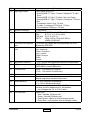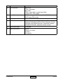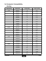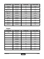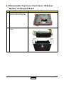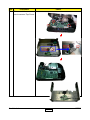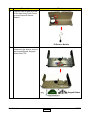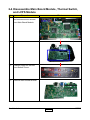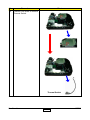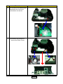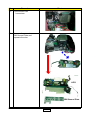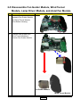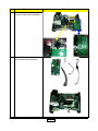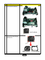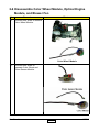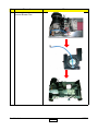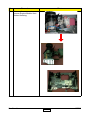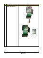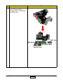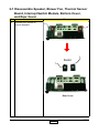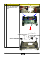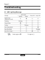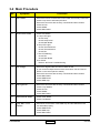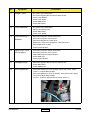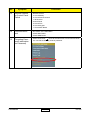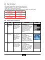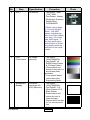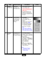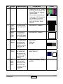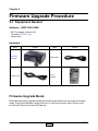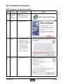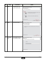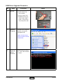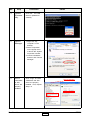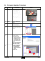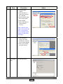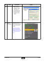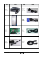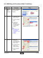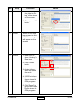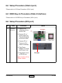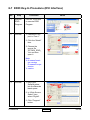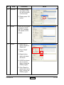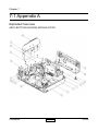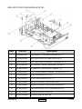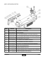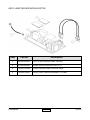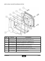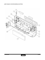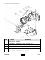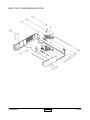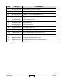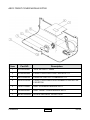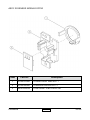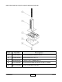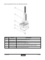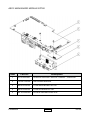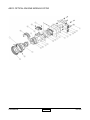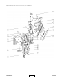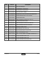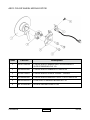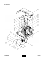
1
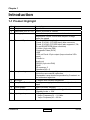
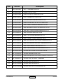
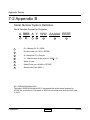
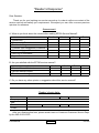
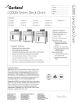
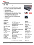
SERVICE MANUAL
Model Name : EP780
Prepared by SI :
________________________________________
Prepared by TSE :
________________________________________
Checked by :
________________________________________
Approved by :
________________________________________
Date
Version
Description
2006/9/29
V1.0
Initial Issue
2006/12/6
V2.0
modify “Chapter 5 Fireware Upgrade”
Copyright Sep, 2006. All Rights Reserved
P/N#36.85Y03G001
Preface
This manual is applied to EP780 professional video scaler and color management
system. The manual gives you a brief description of basic technical information to help in
service and maintain the product.
Your customers will appreciate the quick response time when you immediately
identify problems that occur with our products. We expect your customers will appreciate
the service that you offer them.
This manual is for technicians and people who have an electronic background.
Please send the product back to the distributor for repairing and do not attempt to do
anything that is complex or is not mentioned in the troubleshooting.
Notice:
The information found in this manual is subject to change without prior notice. Any
subsequent changes made to the data herein will be incorporated in future edition.
EP780Service Manual
Copyright Sep, 2006
All Rights Reserved
Manual Version 1.0
P/N#36.85Y03G001
Confidential
I
EP780
Table of Contents
Chapter 1 Introduction
1-1
Product Highlight
1-1
Computer Compatibility
1-2
Chapter 2 Disassembly Procedure
2-1
Equipment Needed
2-1
Disassemble Lamp Module and Elevator Foot
2-2
Disassemble Top Cover, Front Cover, IR Sensor Module,
and Keypad Board
2-3
Disassemble Main Board Module, Thermal Switch, and
LVPS Module
2-4
Disassemble Fan Guider Module, Wind Tunnel Module,
Lamp Driver Module, and Axial Fan Module
2-5
Disassemble Color Wheel Module, Optical Engine Module,
and Blower Fan
2-6
Disassemble Speaker, Blower Fan, Thermal Sensor Board,
Interrupt Switch Module, Bottom Cover, and Rear Cover
Chapter 3 Troubleshooting
3-1
LED Lighting Message
3-1
Main Procedure
3-2
Chapter 4 Function Test and Alignment Procedure
4-1
Test Equipment Needed
4-1
Service Mode
4-2
Test Condition
4-3
Inspection Procedure
4-4
Chapter 5 Firmware Upgrade Procedure
Confidential
2-7
5-1
Equipment Needed
5-1
Installation Procedure
5-2
Firmware Upgrade Procedure
5-3
II
EP780
Chapter 6 EDID Upgrade Procedure
6-1
EDID Introduction
6-1
Setup Procedure (VGA-1 port)
6-2
EDID Key-in Procedure (VGA-1 Interface)
6-3
Setup Procedure (VGA-2 port)
6-4
EDID Key-in Procedure (VGA-2 Interface)
6-5
Setup Procedure (DVI port)
6-6
EDID Key-in Procedure (DVI Interface)
6-7
Chapter 7 Appendix A
7-1
Exploded Overview
7-1
Appendix B
7-2
Serial Number System Definition 7-2
Reader’s Response
7-3
Confidential
III
EP780
Chapter 1
Introduction
1-1 Product Highlight
No
1
2
3
4
5
6
7
8
9
10
Item
Description
Weight
Approx. 8 lbs
Dimension (W x D x H) 335mm X 250mm X 100mm
Cooling system
Fans with low system acoustic noise level
Temperature control circuits with adaptive voltage
control fan speed
Connect I/O port
- DVI D (HDCP Compliant)
- D-sub 15 VGA 1 (PC RGB input) blue connector
- D-sub 15 VGA 2 (PC RGB input) also supports Y, Pb,
Pr and SCART/RGB (blue connector)
- S-Video (4 pin mini DIN)
- Composite Video (RCA)
- USB
- VGA out D-sub 15 pin output (loop out active VGA
input)
- 3 Audio in
- Audio out
- RS232 (3 pin mini DIN)
- RJ45
- IR sensors x 2
- Speakers 2W x 2
Lamp housing
- Lamp could be changed by customer, but should
follow the user manual insturction.
- Replacable Lamp should be provided by Coretronic or
its authouized agencies.
Tilt angle:
- 7 degree with elevator mechanism
Lamp Door Protection
- Lamp power supply shut off actomatically when door
open
Power supply
- Inpu 100-240V, 50/60Hz
Power Consumption
- Normal operation: 385W+/-10%@110V AC
- Standby mode: < 12W
Input signal spec.
PC Signal
- Hsync Frequency 31 ~ 91.1kHz
- Vsync Frequency 43 ~ 85 Hz
Confidential
1-
EP780
NO
10
11
12
13
14
15
16
17
Name
Input signal spec.
Description
Video Signal RGB (PC)
- Analog RGB 0.7 Vp-p, 75 ohms, Separate TTL H&V
Sync
- Analog RGB 1.0 Vp-p, 75 ohms, Sync on Green
- Analog RGB 0.7 Vp-p, 75 ohms, Composite TTL Sync
Video
- Composite video 1Vp-p, 75 ohm
- S-video Luminance 0.714Vp-p, 75 ohm
- Chrominance 0.286Vp-p, 75 ohm
System Controller
- TI DDP3020
Video compatibility
- NTSC : M(3.58MHz),4.43 MHz, 480i
- PAL :
B, D, G, H, I, M, N; 60Hz
- SECAM : B, D, G, K, K1, L
- HDTV :
480p, 576i/p, 720p 50 & 60 Hz,
1080i/p 50 & 60Hz
UXGA/SXGA Compres- - UXGA/SXGA images will be compressed into XGA
sion
display by DDP3020
Projector control key- Menu
pad
- Up / keystone
- Down / keystone
- Left / source
- Right / re-sync
- Enter
- Power
Keystone correction
+- 16% vertical and horizontal keystone compensation
Brightness
- 3350 ANSI Lumens(Typical)
- 2850 ANSI Lumens (Minimum)
Contrast ratio
- 2500 : 1 full on/full off (Typical)
- 1700 : 1 full on/full off (minimum)
18
19
Uniformity
Projection lens
20
Throw distance
21
Aspect ratio
22
LED indicator
Confidential
- 65% minimum
- 1.2 x zoom lens, 2.0 to 2.4 throw ratio with thread to
attach long throw and short throw lens
- 1.2~10m (Optical Performance)
- 1.0~12.2m (Mechanical travel)
- 4:3 with support for 5:4, 16:9 and 2.35:1.
(Vertical po sition adjustment for all letterbox
- can’t support the 5:4 & 2.35:1 ratio)
Power LED
- Red : Standby (Projector off)
- Green : Normal (Projector on)
- Flash Green : Warm up (Go to Normal mode)
- Flash Red : Cooling down (Go to Standby mode)
1-
EP780
No Item
22 LED indicator
Description
Temp. LED
- Red : Overheat
Lamp LED
- Red : Lamp bad or ignite lamp failed
- Flash Red : Fan locked
- 2000 hours typical, 50% survival rate Full Power
- 3000 hours ECO mode
- Osram 300W E21.8 G2 lamp
23
Lamp life
24
Lamp type
25
QSC
- With 18 languages : English, German, French, Italian,
Spanish,Portuguese,Polish, Dutch, Russian, Finnish,
Swedish, Norweigian/Dannish, Traditional Chinese,
Simplified Chinese, Japanese, Korea, Greek
26
Quick shut down
- 2 minutes
27
Input connectors
- DVI-D
- D-Sub 15 VGAx2
- S-Video
- Composite
Confidential
1-
EP780
1-2 Computer Compatibility
Analog
Compatibility
Resolution
V-Sync [Hz]
H-Sync [KHz]
VGA
640x350
70
31.5
640x350
85
37.9
640x400
85
37.9
640x480
60
31.5
640x480
72
37.9
640x480
75
37.5
640x480
85
43.3
720x400
70
31.5
720x400
85
37.9
800*600
56
35.2
800x600
60
37.9
800x600
72
48.1
800x600
75
46.9
800x600
85
53.7
1024x768
60
48.4
1024x768
70
56.5
1024x768
75
60.0
1024x768
85
68.7
1152x864
70
63.8
1152x864
75
67.5
1152x864
85
77.1
1280x1024
60
63.98
1280x1024
75
79.98
1280x1024
85
91.1
SVGA
XGA
SXGA
Confidential
1-
EP780
Compatibility
Resolution
V-Sync [Hz]
H-Sync [KHz]
SXGA+
1400x1050
60
63.98
UXGA
1600x1200
60
75
MAC LC 13”
640x480
66.66
34.98
MAC II 13”
640x480
66.68
35
MAC 16”
832x624
74.55
49.725
MAC 19”
1024x768
75
60.24
MAC
1152x870
75.06
68.68
MAC G4
640x480
60
31.35
i Mac DV
1024x768
75
60
i Mac DV
1152x870
75
68.49
i Mac DV
1280x960
60
60
Compatibility
Resolution
V-Sync [Hz]
H-Sync [KHz]
VGA
640x350
70
31.5
640x350
85
37.9
640x400
85
37.9
640x480
60
31.5
640x480
72
37.9
640x480
75
37.5
640x480
85
43.3
720x400
70
31.5
720x400
85
37.9
800x600
72
48.1
Digital
Confidential
1-
EP780
Compatibility
Resolution
V-Sync [Hz]
H-Sync [KHz]
SVGA
800x600
56
35.2
800x600
60
37.9
800x600
72
48.1
800x600
75
46.9
800x600
85
53.7
1024x768
60
48.4
1024x768
70
56.5
1024x768
75
60.0
1024x768
85
68.7
1152x864
70
63.8
1152x864
75
67.5
1152x864
85
77.1
1280x1024
60
63.98
1280x1024
75
79.98
1280x1024
85
91.1
SXGA+
1400x1050
60
63.98
UXGA
1600x1200
60
75
XGA
SXGA
Confidential
1-
EP780
Chapter 2
Disassembly Procedure
2-1 Equipment Needed
Item
Photo
Item
Screw Bit (+)
:107
Hex Sleeves
5mm
Screw Bit (+)
:101
Screw Bit:
6.0 x 100
Confidential
2-
Photo
EP780
2-2 Disassemble Lamp Module and Elevator Foot
No
Procedure
1 Unscrew two screws to
remove Lamp Cover.
Photo
Lamp Cover
2
Unscrew three screws to
remove Lamp Module.
Lamp Module
Confidential
2-
EP780
No
Procedure
3 (1) Unscrew two screws to
detach Elevator Foot from
Bottom Housing.
Photo
(2) Lift it and then unscrew the
screw.
Elevator Foot
Confidential
2-
EP780
2-3 Disassemble Top Cover, Front Cover, IR Sensor
Module, and Keypad Board
No
Procedure
1 Unscrew eight screws and
then turn unit to the top side.
2
Photo
Loose Front Cover from Top
Cover.
Confidential
2-
EP780
No
Procedure
3 Disconnect three connectors to remove Top Cover.
Confidential
Photo
2-
EP780
No
Procedure
4 Unscrew two screws and tear
off the tape from Front Cover
to remove the IR Sensor
Module.
Photo
IR Sensor Module
5
Unscrew three screws and
disconnect the wire to remove
the Keypad Board, Keypad
Button and FFC.
Confidential
2-
EP780
2-4 Disassemble Main Board Module, Thermal Switch,
and LVPS Module
No
Procedure
1 Disconnect eleven connectors
and unscrew seven screws
from Main Board Module.
2
Unscrew eight hex screws
from Bottom Cover.
3
Remove Main Board Module.
Confidential
Photo
2-
EP780
No
Procedure
4 Unscrew one screw to remove
Thermal Switch.
Photo
Thermal Switch
Confidential
2-
EP780
No
Procedure
5 Pull up the LVPS Module and
disconnect the connector.
(1)Unscrew one screw.
Photo
(2)Unscrew four screws to
remove the Rear Cover.
Confidential
2-
EP780
No
Procedure
5 (3)Disconnect two
connectors.
6
Photo
Unscrew the screw to remove
EMI Ground Plate and
separate the wire.
LVPS
EMI Ground Plate
Confidential
2-10
EP780
2-5 Disassemble Fan Guider Module, Wind Tunnel
Module, Lamp Driver Module, and Axial Fan Module
No
Procedure
1 Unscrew three screws to
separate Fan Guider Module
and Wind Tunnel Module
from Bottom Housing.
2
Photo
Unscrew two screws from
Wind Tunnel Module to
remove Fan Guider Module.
Fan Guider Module
Wind Tunnel Module
Confidential
2-11
EP780
No
Procedure
3
Unscrew five screws to
remove Lamp Driver Module.
4
Separate three connectors
from Lamp Driver Module.
Confidential
Photo
2-12
EP780
No
5
Procedure
Photo
Unscrew two screws to
remove Axial Fan Module.
Axial Fan Module
6
Unscrew four screws to
separate Fan Hoder Bracket
and Axial Fan.
Axial Fan Module
Confidential
2-13
Fan Hoder Bracket
EP780
2-6 Disassemble Color Wheel Module, Optical Engine
Module, and Blower Fan
No
Procedure
1
Unscrew one screw to remove
Color Wheel Module.
Photo
Color Wheel Module
2
Unscrew one screw to
separate Color Wheel and
Photo Sensor Module.
Confidential
2-14
EP780
No
3
Procedure
Photo
Unscrew two screws to
remove Blower Fan.
Confidential
2-15
EP780
No
4
Procedure
Photo
Unscrew four screws to
remove Engine Module from
Bottom Housing.
Confidential
2-16
EP780
No
5
Procedure
Photo
Unscrew four screws to
remove DMD Heat sink.
DMD Heat sink
Confidential
2-17
EP780
No
6
Procedure
Photo
Unscrew four screws to
remove Bracket Plate,
Insulation Mylar, DMD Board
and DMD Chip.
DMD Chip
DMD Board
Insulation Mylar
Bracket Plate
Confidential
2-18
EP780
2-7 Disassemble Speaker, Blower Fan, Thermal Sensor
Board, Interrupt Switch Module, Bottom Cover,
and Rear Cover
No
1
Procedure
Photo
Unscrew four screws to
remove Speaker.
Rear Cover
Confidential
2-19
EP780
No
Procedure
Photo
2
Unscrew six screws to remove
Blower Fan, Elevator Shading
Mylar, and Thermal Sensor
Board.
Thermal Sensor Board
Blower Fan
Interrupt Switch Module
Elevator Shading Mylar
Bottom Cover
Confidential
2-20
EP780
Chapter 3
Troubleshooting
3-1 LED Lighting Message
Confidential
3-
EP780
3-2 Main Procedure
No
Symptom
Procedure
1
No Power
- Ensure the Power Cord and AC Power Outlet are securely connected
- Check Lamp Cover and Interrupt Switch
- Ensure all connectors are securely connected and aren’t broken
- Check DC-DC
- Check Ballast
- Check Main Board
2
Auto Shut Down
- Check LED Status
a. Lamp LED Light
- Check Lamp
- Check Lamp Driver
- Check Main Board
b. Temp LED Light
- Check Thermal Sensor
- Check Thermal Switch
- Check Fan
c. Tem LED Blinking
- Check Fan
- Check Main Board
d. No Power
- Refer to “No Power” troubleshooting
3
No Image
- Ensure the Signal Cable and Source work as well
(If you connect multiple sources at the same time, use the “Source”
button on the control panel to swtich)
- Ensure all connectors are securely connected and aren’t broken
- Check Main Board
- Check DMD Board
- Check DMD Chip
4
No Light On
- Ensure all connectors are securely connected and aren’t broken
- Check Lamp Module
- Check DC-DC
- Check Ballast
- Check Main Board
5
Mechanical Noise
- Check Color Wheel
- Check Fan Module
6
Line Bar / Line
Defect
- Sometimes it’s because of the DMD Chip and the DMD Board did
not assemble properly
- Check DMD Board
- Check DMD Chip
- Check Main Board
Confidential
3-
EP780
No
Symptom
Procedure
7
Image Flicker
- Do “Reset” of the OSD Menu
- Ensure the Signal Cable and Source work as well
- Check Lamp Module
- Check Color Wheel
- Check DMD Board
- Check Main Board
8
Color Abnormal
- Do “Reset” of the OSD Menu
- Adjust Color Wheel Index
- Check Main Board
- Check Color Wheel
9
Poor Uniformity /
Shadow
- Ensure the Projection Screen without dirt
- Ensure the Projection Lens is clean
- Ensure the Brightness is within spec.
(Replace the Lamp if the Brightness is less than spec.)
- Ensure DMD Chip is clean
- Check Engine Module
10
Dead Pixel / Dust
(Out of spec.)
- Ensure the Projection Screen without dirt
- Ensure the Projection Lens is clean
- Clean DMD Chip and Engine Module
- Check DMD Chip
- Check Engine Module
11
Garbage Image
- Ensure the Signal Cable and Source work as well
- Check Main Board
- Check DMD Board
12
ROD adjustment
- If there are shadows at “Left” & “Right” side of the screen, adjust
“Screw 1” to adjust ROD position.
- If there are shadows at “TOP” & “Bottom” side of the screen, adjust
“Screw 2” to adjust ROD position.
- “Screw 1” should be adjusted first, and then “Screw 2”.
Confidential
3-
EP780
No
Symptom
Procedure
13
Remote Controll
or Control Panel
Failed
- Remote Control
a. Check Battery
b. Check Remote Control
c. IR Receiver
- Control Panel
a. Check FPC
b. Check Keypad
c. Check Main Board
14
Function Abnormal
- Do “Reset” of the OSD Menu
- Check Main Board
- Check DMD Board
15
Forgetting Password (administrator Password)
- Press “Enter” and “ “ arrow at the same time to enter Service Mode.
You can find the Security Code is password.
Confidential
3-
EP780
Chapter 4
Function Test & Alignment Procedure
4-1 Test Equipment Needed
- IBM PC with XGA resolution (Color Video Signal & Pattern Generator)
- DVD player with Multi-system (NTSC/PAL/SECAM), equipped “Component”, “S-Video”
and “Composite”
- HDTV Tuner or Source (480P, 720P, 1080i)
- Minolta CL-100
- Quantum Data 802B or CHROMA2327
- After changing parts, check the information below.
Color
Wheel
Index
Charge
Parts/Update
Version
Update
M/B
v
v
FW
v
v
Color Wheel
ADC
Calibration
Video
Calibration
v
v
Reset Lamp
Use Time
Factory
Reset
EDID
v
v
v
v
4-2 Service Mode
No
Item
1
Service
Mode
1. Turn on the projector.
2. Press and hold “Enter” and “ “ arrow at the same time.
2
Factory
Reset
After final QC step, we have to erase all saved change again and
restore the factory defaults. The following actions will allow you to
erase all end-users’ settings and restore the original setting:
1. Please enter the servcie mode,
2. Choose “ Information and Reset “ item.
3. Choose “Factory Reset” then choose “Yes” and press “Enter” to
see if it works.
Confidential
Step
4-
EP780
4-3 Test Condition
- Circumstance Brightness : Dark room less than 2.5 lux.
- Inspection Distance : 1.5m~3m for functional inspection
- Screen Size : 60 inches diagonal (wide)
- After repairing each HD72, the unit should be run-in (Refer to the table below).
Symptom
Run-in Time
Normal Repair
2 Hours
NFF
4 Hours
Auto Shutdown
6 Hours
4-4 Inspection Procedure
No
Step
Specification
Procedure
1
Frequency
and Tracking
Eliminate visual
wavy noise by
Rsync, Frequency or Tracking
selection.
- Test Signal :
1024x768@60Hz
- Test Pattern :PANA-ICON
- check and see if image
sharpness and focus
are well-performed.
- No video noise is allowed.
2
Boundary
Horz. And Vert.
position of
video should be
adjustable to
be the screen
frame.
- Test Signal :
1024x768@60Hz
- Test Pattern : General 1
- Adjust Resync or
Frequency / Tracking /
H. Position / V. Position
to the inner of the screen.
3
Focus
The text in the
corner should be
clear after adjust
the focus ring.
- Test Signal :
1024x768@60Hz
- Test Pattern : Full Screen
- Adjust the center clearly;
meanwhile, one slightly
vague corner in the im
age is allowed.
Confidential
4-
Photo
EP780
No
4
Step
HDTV
Specification
No discolor
Procedure
Photo
- Test Signal : 480P,
720P, 1080i
- Test Pattern : Master
- Equipment: Quantum
Data 802B or
CHROMA2327
*Please refer to page
4-1 to enter Service
Mode. Use 480P
signal, smtpebar pattern to do video calibration; then, 4:3 screen
and 1080i signal. If
the test result was in
discoloration or flickering, please return the
unit back to the repair
center.
5
Color
Performance
No image
(discolor)
- Test Signal :
1024x768@60Hz
- Test Pattern : 64
RGBW Scale Pattern
& 32 Grays Pattern
- Please check and
ensure if each color is
normal and distinguishable.
- If not, please adjust
color index of the
Engineering Mode.
6
Screen Uniformity
Should be
compliant with
60%.(Minimum)
- Test Signal :
1024x768@60Hz
- Test Pattern : Full
White Pattern & Full
Black Pattern
- Please check and
ensure the unit is
under the spec.
- Please check and see
if it’s in normal conidtion.
Confidential
4-
EP780
No
Step
Specification
Procedure
6
Screen
Uniformity
Should be
compliant with
60%.(Minimum)
- If not, please return the
unit to repair area.
*Please check and see if
there are dead pixels on
DMD Chip.
- The total number and
distance of dead pixels
should be compliant with
the spec.
7
Light Leak
The unit can’t
accept the leakage is brighter
then Gary 10
pattern
- Test Signal :
1024x768@60Hz
- Test Pattern : Gray 10
Pattern
- Please check and see if
the light leaks *Note
- The unit cannot accept
the leakage is brighter
than Gray 10 Pattern
Note:
Light leak on reflective
edge, eyecatcher, bond
wires and exposed metal.
8
Calibration
Calibration Pattern should be in
full screen mode
- Once Main Board is
changed, Video Calibration
& PC Calibration should be
done as well.
- Video Calibration
- Test Signal : 480P@60Hz
- Test Pattern : SMPTE bar
- ADC Calibration
(PC Calibration)
- Test
Signal:1024x768@60Hz
- Test Pattern : White (Top)
Black (Bottom)
Photo
Note:
1. Calibration Pattern
should be in Full
Screen Mode.
Confidential
4-
EP780
No
Step
Specification
Procedure
Photo
2. Please refer to 4-2. Guide to
Entering Service Mode and
Facotry Reset for entering
Service Mode.
3. Choose and access Video
Calibration & PC Calibration
for correction in Service
Mode. Choose “Exit” to
leave the Service Mode
after all.
9
Dead
Pixel
(Bright
pixel)
Cannot accept
any bright pixel
- Test Pattern : Full Black
Dead
Pixel
(Dark
pixel)
The numbers
of dead pixel
should be smaller or amount to
6 pixel.
- Test Pattern : Full White
10
Blemish
(Bright)
The bright blemish cannot be
accepted if the
problem appear
with Gary 30
pattern
- Test Pattern :
Full Black /
Gray 30
11
Blemish
(Dark)
The dark blemish cannot be
accepted if the
problem appear
with Blue 60
pattern.
- Test Pattern : Full
white / Blue 60
12
Network
hardware
When network
link correctly,
the LED in network card will
change to green
from flash
yellow .
- Plug in the network , check
the LED.
Confidential
4-
EP780
Chapter 5
Firmware Upgrade Procedure
5-1 Equipment Needed
Software : (DDP 3020-USB)
- DLP Composer (Version 6.0)
- Firmware (EP780*.img)
- Library files
Hardware :
Item
Photo
Item
Projector
(EP780)
USB Cable
Power Cord
PC or
Laptop
Photo
Firmware Upgrade Mode:
Before doing firmware upgrade, please get into firmware mode first. How to get in firmware
mode: Press and hold Menu button then turn on the Power switch. Menu button must
be held until Temp and Lamp LED light up.
Confidential
5-
EP780
5-2 Installation Procedure
DLP Composer Lite Setup Procedure
No
Step
Procedure
1
Execute
FW
program
Choose
“DLP Composer Lite
v6.0 Setup” program.
2
Next
Click “Next” button.
3
Next
1. Reading the “License
Agreement” rules.
2. Choose “I accept and
agree to be bound by
all the terms and
conditions of this
License Agreement”
icon.
3. Click “Next” button.
4
Next
Click “Next” button.
Confidential
Photo
5-
EP780
No
Step
Procedure
5
Next
1. Choose “All” icon.
2. Click “Next” button.
6
Next
Click “Next” button.
7
Processing
The program is executing “Initializing” status.
Confidential
Photo
5-
EP780
USB Driver Upgrade Procedure
No
Step
Procedure
1
Set-up
1. Plug in USB cable
2. Press "Enter" key
don't release
3. Plug in Power cord
4. Release "Enter" key
when Power LED is
green, Lamp LED is
red, Temp Led is red.
2
Execute
Program
Execute the C:\Program
files\DLP Composer\
usbupdate.cmd
Photo
(Note: The “DLP Composer” program must be
closed first.)
3
Type any
key to
continue
Confidential
Press any key to continue. Then, wait for about
1 minute.
5-
EP780
No
Step
4
Update
Successfully
Click “OK”. The USB
driver is updated successfully.
5
Device
Manager
1. Right click “My
computer” on the
desktop.
2. Select “Properties”
on the popup menu
to launch the “System
Properties” window.
3. Choose “Hardware”
and then click “Device
Manager”.
6
Ensure
“DDP3020”
& “WinDriver” are
properly
installed
Click “Jungo” to ensure
“DDP3020” and “Windriver” are properly
installed. If not, repeart
Step 1~5.
Confidential
Procedure
Photo
Device Manager
5-
EP780
5-3 Firmware Upgrade Procedure
No
Step
Procedure
1
Set-up
1. Plug in USB cable.
2. Press "Enter" key
don't release.
3. Plug in Power cord.
4. Release "Enter" key
when Power LED is
green, Lamp LED is
red, Temp Led is red.
2
Set-up
Link PC USB and projector
3
Execute the “DLP
Compose(TM)Lite 6.0”.
4
Click “Edit” and “Preferences”.
Photo
1
2
5
1. Click “Library”.
2. The library path
located in the default
installation directory
is C:\Program Files\
DLP Composer Lite
6.0
If not, press “Browse” to
select the right path.
6
1. Select “Edit\Prefer
ences\Communi
cations” and choose
“USB”.
2. Click “OK”.
1
USB
Vendor: 0x451
Product: 0x2000
2
OK
Confidential
5-
EP780
No
Step
7
Procedure
Photo
1. Choose “Flash
Loader”
2. Click “Browse” to
search the firmware
file. (EP780)
3. Select the item “Skip
Boot Loader Area”.
4. Select 64KB.
5. Click “Reset Bus” to
erase the flash
memory.
1
2
3
4
5
Note: If the error message “cannot open USB
driver - No projectors
found” appears, please
ueplug the USB Cable
and replug.
8
1. If the firmware is
ready, click “Start
Download” to process
the firmware upgrade.
2. Click “Yes” to erase
the flash memory.
2
1
9
Proceeding
Confidential
Proceeding Picture
5-
EP780
No
Step
10
11
Procedure
Photo
1. When Firmware
Upgrade Process is
finished, the LED
power light on.
2. Unplug USB Cable
and Power Cord.
Re-plug in Power
Cable.
Check
Firmware
Restart the unit and
enter the Service Mode
to check the Firmware
Version.
(For entering Service
Mode, please refer to
Chapter 4 Function Test
and Alignment Procedure.)
Confidential
5-
EP780
Chapter 6
EDID Key-in Procedure
Extended Display Identification Data is a VESA standard data format that contains basic
information about a display device and its capabilities, including vendor information, maximum
image size, color characteristics, factory pre-set timings, frequency range limits, and character
strings for the EP780 and serial number.
The information is stored in the display and is used to communicate with the system through
a Display Data Channel (DDC ), which sites between the display device and the PC graphics
adapter. The system uses this information for configuration purposes, so the EP780 and
system can work together.
Note: If a display device has digital input ports, like DVI or HDMI, but without EDID in its main
board, the display device will show no image while the input source is digital signal.
6-1 Equipment Needed
Software
-
EDID.exe
EP780X_EDID_Y.ini
-
Hardware
-
EP780
-
PC
-
RS 232 9 pin cable (Male to Female, pin to pin)
-
Power Cord for EP780
-
VGA Cable
-
DVI Cable
-
EDID Fixture (JP3 must be closed)
-
Power Adapter for Fixture and Power Cord
Confidential
6-
EP780
Item
EP780
Projector
Photo
Item
RS-232
Cable
(F to M)
PC
VGA
Cable
EDID
Fixture
DVI
Cable
Power
Adapter
Power
Cord
Confidential
Photo
6-
EP780
6-2 Setup Procedure (VGA-1 port)
No
1
Step
Connect
all ports
Procedure
Photo
1. Connect P1 of
Fixture with Com
Port of PC/Laptop
by RS232 Cable.
2. Connect P2 of
Fixture with VGA
-1 port of EP780
by VGA Cable.
3. Plug Power
Adapter to Fixture
and Power Cord.
VGA-1
VGA-2
4. Plug Power Cord
to EP780 unit.
Note: Confirm JP3 is
“Close” status.
Confidential
VGA port
6-
EP780
6-3 EDID Key-In Procedure (VGA-1 Interface)
No
Step
Procedure
1
Execute
EDID
Program.
Click on “EDID.exe”
to execute EDID
Program.
2
Process
1. Check the Com
port is “Com 1”.
Photo
2
2. Click the “Model”
item.
3. Choose the
source file
“EP780X_EDID_
Y.ini and then
open it.
3
1
4
Note:
X: A means American version
E means Europe
version
Y: version
3
Process
1. Key in the
Serial Number
into the Barcode
blank space.
1
2
2. In “Write Source
Select” item,
select “Analog”.
2. Click “Program”
button.
Confidential
6-
EP780
No
4
Step
Process
Procedure
Photo
1. “Please change
the cable to Analog” will be shown
on the screen.
2. Please press “Ok”
button.
5
Finish
When EP780 Analog program is finish,
the “Ok” message
will appear on the
screen.
6
Check
1. Make sure to
check “Analog” in
Read item.
3
2
2. Press “Read”
button.
4
1
3. Analog Informations will show
the result.
4. If EDID’s information is correct,
then to close the
EDID program.
5. Click “Reset” to
do the next unit or
“Exit” to close the
EDID program.
Confidential
6-
EP780
6-4 Setup Procedure (VGA-2 port)
*Please refer to 6-2 Setup Procedure (VGA-1 port).
6-5 EDID Key-In Procedure (VGA-2 Interface)
*Please refer to 6-3 EDID Key-In Procedure (VGA-1 port).
6-6 Setup Procedure (DVI port)
No
1
Step
Connect
all ports
Procedure
Photo
1. Unplug VGA
cable from fixture
and EP780.
2. Connect P1 of
Fixture with Com
Port of PC/Laptop
by RS232 Cable.
3. Connect P3 of
Fixture by DVI
cable for standby.
4. Plug Power
Adapter to Fixture
and Power Cord.
DVI port
5. Plug Power Cord
to EP780 unit.
Note: Confirm JP3 is
“Close” status.
Confidential
6-
EP780
6-7 EDID Key-In Procedure (DVI Interface)
No
Step
Procedure
1
Execute
EDID
Program.
Click on “EDID.exe”
to execute EDID
Program.
2
Process
1. Check the Com
port is “Com 1”.
Photo
2
2. Click the “Model”
item.
3. Choose the
source file
“EP780X_EDID_
Y.ini and then
open it.
3
1
4
Note:
X: A means American version
E means Europe
version
Y: version
3
Process
1. Key in the
Serial Number
into the Barcode
blank space.
1
2
2. In “Write Source
Select” item,
select “Digital”.
2. Click “Program”
button.
Confidential
6-
EP780
No
4
Step
Process
Procedure
Photo
1. “Please change
the cable to Digital” will be shown
on the screen.
2. Please press “Ok”
button.
5
Finish
When EP780 Digital
program is finish,
the “Ok” message
will appear on the
screen.
6
Check
1. Make sure to
check “Digital” in
Read item.
3
2
2. Press “Read”
button.
4
1
3. Digital Informations will show
the result.
4. If EDID’s information is correct,
then to close the
EDID program.
5. Click “Reset” to
do the next unit or
“Exit” to close the
EDID program.
Confidential
6-
EP780
Chapter 7
7-1 Appendix A
Exploded Overview
ASSY BOTTOM HOUSING MODULE EP780
Confidential
7-
EP780
Item
Part NO
1
51.85Y02G002
LVPS FAN GUIDE FORMAX EP780
2
51.89633G002
ELEVATOR SHADING MYLAR EP771
3
52.85Y11G001
THERMAL PAD
4
52.89601G001
ADJUST FOOT RUBBER EP771
5
52.89605G001
REAR FOOT RUBBER EP759/PD726
6
52.89631G002
LAMP TO BTM INSULATOR RUBBER EP771
7
70.83N16G001
ASSY INTERRUPT SWITCH MODULE PD726
8
70.83N17G001
ASSY BLOWER FAN 50*20 MODULE PD726
9
70.85Y02G001
ASSY BOTTOM COVER MODULE EP771
10
70.85Y03G001
ASSY LVPS MODULE EP771
11
70.85Y04G001
ASSY LAMP DRIVER MODULE
12
70.85Y05G001
ASSY AXIAL FAN 92x25 MODULE EP771
13
70.85Y07G001
ASSY BACK COVER MODULE EP771
14
75.89607G061
ASSY PRE ELEVATOR MODULE EP771
15
75.89608G062
ASSY WIND TUNNEL MODULE EP780
16
85.1A123G060
SCREW PAN MECH M3*6 NI
17
85.TA326G070
SCREW CAP TAP M2.6*7 WASHER
18
85.WA123G060
SCREW PAN TAP M3*6 NI
19
85.WD123G080
SCREW PAN TAP 3*8 W/WASHER NI
20
86.03123G035
HEX CAP HEAD NUT M3*0.5P L3.5
Confidential
Description
7-
EP780
ASSY BOTTOM COVER MODULE EP780
Item
Part NO
Description
1
41.89602G001
EMI GASKET FOR DMD HEATSINK EP771
2
51.89602G062
BOTTOM COVER PC+ABS C6200 EP771
3
52.85Y01G001
BOTTOM COVER SPONGE CVSBXXB EP771
4
52.85Y02G001
STEAMTIGHT NEAR FAN GUIDE F12 EP771
5
52.89610G001
STEAMTIGHT NEAR WIND TUNNEL F12
6
52.89620G001
TOP COVER SMALL SPONGE FOR NOISE EP771
7
61.85Y02G001
LVPS HOLDER SECC EP771
8
61.85Y03G001
LVPS TOUCH SINK AL EP771
9
61.89628G002
MESH-1 FOR BOTTOM COVER EP771
10
61.89632G002
MESH-2 FOR BOTTOM COVER IRON EP771
11
61.89634G001
HEX SPACER M3 H=23 L=6 BRASS PD726
12
85.1A123G060
SCREW PAN MECH M3*6 NI
13
85.WA123G060
SCREW PAN TAP M3*6 NI
Confidential
7-
EP780
ASSY LVPS MODULE EP780
Item
Part NO
1
41.82L07G001
EMI GASKET IO RCA ARES
2
41.85Y04G001
EMI I/O GASKET
3
42.89601G001
W.A. 16P 80mm MAIN BD TO LVPS EP759/PD726
4
42.89611G001
W.A. 3P 250mm LAMP DRIVER TO LVPS EP759/PD726
5
49.82G01G001
MISC BLOWER 45*20; DELTA
6
51.85Y03G001
LVPS INSULATOR FORMAX 0.4t EP771
7
61.85Y01G001
EMI GROUND PLATE SECC 0.6t EP771
8
75.85Y02G001
BUY ASSY LVPS EMI/BLOWER HOLDER MODULE
9
75.85Y03G001
ASSY LVPS QUASAR EP780
10
85.1A123G060
SCREW PAN MECH M3*6 NI
11
85.1C224G050
SCREW PAN MECH M4*5 COLOR W/TOOTH WASHER
12
85.1F123G260
SCREW PAN MECH E/SF M3*26 Ni
Confidential
Description
7-
EP780
ASSY LAMP DRIVER MODULE EP780
Item
Part NO
1
42.89608G001
W.A. 5P #28 200mm LAMP DRIVER
2
51.89639G001
LAMP DRIVER EMI MYLAR EP771
3
75.80L01G004
ASSY OSRAM LAMP DRIVER 300W
4
76.89601G001
ASSY LAMP DRIVER(OSRAM) TO LAMP
Confidential
Description
7-
EP780
ASSY AXIAL FAN 92*25 MODULE EP780
Item
Part NO
1
49.83C04G001
SUNON 9225 AXIAL FAN/KDE1209PTBX
2
52.89602G001
FAN 92*25 STEAMTIGHT RUBBER EP771
3
52.L1308G002
FAN 9225 RUBBER BOTTOM H76/PD726
4
52.L1309G001
FAN 9225 RUBBER TOP H76/PD726
5
61.86633G001
PANAFLO 92*25 AL FOIL H76/PD726
6
61.89607G001
FAN 9225 HOLDER BRACKET AL 0.8t EP759
7
61.L1322G001
SCREW FOR 9225 FAN H76
Confidential
Description
7-
EP780
ASSY BACK COVER MODULE EP780
Confidential
7-
EP780
Item
Part NO
1
49.88604G002
SPEAKER 2W 40*28.2*11mm
2
85.WA123G060
SCREW PAN TAP M3*6 NI
3
35.85Y01G001
IO LABEL PC EP771
4
41.81R06G001
EMI GASKET CONDUCTIVE SPONGE
5
51.89641G001
SPEAKER LIGHTCUT FORMAX EP771
6
52.89608G001
SPEAKER SPONGE
7
52.89617G001
IO COVER SPONGE EP771
8
61.89629G001
MESH FOR BACK COVER EP771
9
61.89634G001
HEX SPACER M3 H=23 L=6
10
75.85Y01G001
BUY ASSY BACK COVER EP771
11
85.1A123G060
SCREW PAN MECH M3*6 NI
Confidential
Description
7-
EP780
ASSY ENGINE MODULE EP780
Item
Part NO
1
41.85A15G001
EMI 8*55
2
41.89601G001
EMI GASKET FRONT TO ENGINE EP771
3
61.89646G001
EMI BRASS-SHEET FOR ENGINE EP771
4
70.85Y15G001
ASSY OPTICAL ENGINE MODULE EP771
5
70.85Y16G001
ASSY ENGINE BASE MODULE EP771
6
85.1A126G080
SCREW PAN MECH M2.6*8 NI
Confidential
Description
7-
EP780
ASSY TOP COVER MODULE EP780
Confidential
7-10
EP780
Item
Part NO
1
41.85Y02G001
EMI GASKET W7*H2*L35 mm
2
41.85Y03G001
EMI GASKET W7*H2*L240
3
42.83609G002
CABLE FFC 16P L=200mm EP771
4
51.81541G001
TAPE 3M J350 17*30mm
5
51.89601G062
TOP COVER EP780
6
51.89605G061
KEYPAD EP771
7
51.89606G001
LED LENS EP771
8
51.89619G001
IR LENS TOP EP771
9
51.89635G001
TOP COVER ANTI LIGHT MYLAR EP771
10
52.89620G001
TOP COVER SMALL SPONGE EP771
11
80.85Y06G001
PCBA TOP IR BD FOR EP780
12
80.89606G001
PCBA KEYPAD BOARD EP759
13
85.1D122G030
SCREW PAN MECH M2*3 NI(W/WSHER)
Confidential
Description
7-11
EP780
ASSY FRONT COVER MODULE EP780
Item
Part NO
1
51.81541G001
TAPE 3M J350 17*30mm
2
51.89636G002
FRONT COVER ANTI LIGHT MYLAR EP771
3
52.81Y04G001
FRONT IR LIGHTCUT CVSBXXB EP771
4
52.85Y07G002
FRONT COVER INSULATOR RUBBER HT800 AL FOIL
FOR EP780
5
70.85Y11G001
ASSY IR SENSOR MODULE EP771
6
75.89603G061
ASSY FRONT COVER MODULE EP771
7
85.WA126G060
SCREW PAN HEAD TAP M2.6*6 NI
Confidential
Description
7-12
EP780
ASSY IR SENSOR MODULE EP780
Item
Part NO
1
51.89617G001
IR LENS FRONT RING EP771
2
51.89618G001
IR SENSOR HOLDER EP771
3
80.85Y05G001
PCBA FRONT IR BD FOR EP780
Confidential
Description
7-13
EP780
ASSY ELEVATOR FOOT RIGHT MODULE EP780
Item
Part NO
Description
1
51.89611G001
ELEVATOR BODY NORYL EP771
2
51.89613G061
ELEVATOR FOOT EP771
3
52.89604G001
FRONT FOOT RUBBER EP771
4
61.87220G001
ELEVATOR SPRING 0.D:φ4.5 W.D:φ0.3 L:65mm
5
85.1A123G080
SCREW PAN MECH M3*8 NI
Confidential
7-14
EP780
ASSY ELEVATOR FOOT LEFT MODULE EP780
Item
Part NO
Description
1
51.89611G001
ELEVATOR BODY NORYL EP771
2
51.89613G061
ELEVATOR FOOT EP771
3
52.89604G001
FRONT FOOT RUBBER EP771
4
61.87220G001
ELEVATOR SPRING 0.D:φ4.5 W.D:φ0.3 L:65mm
5
85.1A123G080
SCREW PAN MECH M3*8 NI
Confidential
7-15
EP780
ASSY MAIN BOARD MODULE EP780
Item
Part NO
1
51.00165G001
SPACER SUPPORT MCA-06 "GREEN" ; PINGOOD
2
75.83C11G002
NETWORK MODULE
3
80.85Y01G001
PCBA MAIN BOARD EP780
4
80.85Y03G001
PCBA IO BOARD EP780
5
85.1A123G060
SCREW PAN MECH M3*6 NI
Confidential
Description
7-16
EP780
ASSY OPTICAL ENGINE MODULE EP780
Confidential
7-17
EP780
Item
Part NO
1
00.85Y02G001
BARE PCB L:8 1.6mm DMD BOARD EP780
2
11.009F0G007
CNNT F 203P FOR 720P LGA DMD SOCKET
3
23.80J01G001
DLP 0.7"XGA ZOOM PROJECTION LENS
4
48.83N01G001
DMD 0.7 XGA 12° LVDS TYPE A
5
51.80W46G001
TAPE 3M J350 4*4mm
6
51.83N35G001
DMD HEATSINK MYLAR ON DMD BOARD
7
51.89608G061
FOCUS RING PC+ABS C6200 EP771
8
51.89626G061
REPLACE RING PC+ABS C6200 EP771
9
51.89628G001
ZOOM STOP RING
10
52.89613G001
ENGINE SEAL RUBBER
11
52.89627G001
DMD SEAL RUBBER F12 3.2t EP759
12
52.89633G001
THERMAL PAD 17*13*0.3mm
13
61.83N22G011
DMD HEATSINK AL 1070 EP771
14
61.85926G001
COLOR WHEEL SHOULDER SCREW SB21
15
61.89605G001
DMD BACKER PLATE
16
61.89626G001
HEATSINK SCREW EP759
17
61.89627G011
ENGINE COVER AZ91D EP759/PD726
18
61.89630G001
HEATSINK SPRING EP771
19
61.89638G001
DMD MASK SUS301 0.15t BLACK EP759
20
70.81N35G001
ASSY OFFRAY HEATSINK AL PD726
21
75.89605G061
ASSY ZOOM RING MODULE EP771
22
85.1A123G080
PAN SCREW M3*8 FOR YM-64 FRONT CELL & SP
23
85.1A126G080
SCREW PAN MECH M2.6*8 NI
24
85.4A121G065
SCREW FLAT HEAD TAP M1.7*6.5 Ni PD726
Confidential
Description
7-18
EP780
ASSY ENGINE BASE MODULE EP780
Confidential
7-19
EP780
Item
Part NO
1
23.89602G001
POLYGON MIRROR
2
23.89620G001
CONDENSER 1 Φ26mm BK7
3
23.89620G002
CONDENSER 2 Φ26mm BK7
4
51.81541G001
TAPE 3M J350 17*30mm
5
51.83N29G002
ENGINE ANTI-LIGHT MYLAR EVOLUTION PD726
6
51.85Y06G001
ENGINE MIRROR ANTI LIGHT MYLAR
7
51.89614G001
ENGINE BASE BMC
8
52.83N12G001
LAMP HOUSING STEAMTIGHT TOP F12
9
52.85808G001
PORON-LENS BLACK XB31
10
52.89626G001
LAMP HOUSING STEAMTIGHT SIDE F12
11
61.89602G011
LAMP HOUSING AZ91D EP759/PD726
12
61.89611G001
MIRROR SPRING PLATE
13
61.89617G001
ROD BRACKET AL 0.6t EP759
14
61.89621G001
ROD SPRING SUS301 0.25t EP759
15
70.83N20G001
ASSY ROD MODULE PD726
16
70.85Y17G001
ASSY COLOR WHEEL 5 SEGMENT MODULE EP771
17
85.1A126G040
SCREW PAN MECH M2.6*4 NI
18
85.1A126G080
SCREW PAN MECH M2.6*8 NI
19
85.1A522G080
SCREW PAN MECH NYLOK M2*8 NI
Confidential
Description
7-20
EP780
ASSY COLOR WHEEL MODULE EP780
Item
Part NO
1
23.85Y19G001
COLOR WHEEL Φ48mm R90/Y30/G80/W86/B74
SLEEVE BEARING CW; YO
2
52.89606G001
COLOR WHEEL RUBBER EP759/PD726
3
61.89511G001
COLOR WHEEL SCREW 4100MP " GREEN"
4
61.89608G001
COLOR WHEEL BRACKET SECC 1.2t EP759/PD726
5
80.82G06G001
PCBA PHOTO SENSOR BOARD EP719
6
85.1A126G040
SCREW PAN MECH M2.6*4 NI
Confidential
Description
7-21
EP780
D.C. EP780
Confidential
7-22
EP780
Item
Part NO
1
43.87301G001
90c, TI THERMAL SWITCH
2
51.00001G001
CABLE TIE PG-YJ-80
3
51.89607G062
LAMP COVER PC MN3600 EP780
4
52.89611G001
DUCT RUBBER EP759/PD726
5
61.00018G002
LOCK SCREW PAN MECH M3*8.5-3.5
6
61.89641G001
LAMP COVER AL FOIL 0.1t EP759/PD726
7
70.83N07G001
ASSY LAMP CHANGER MODULE PD726
8
70.83N15G001
ASSY BLOWER FAN 60*25 MODULE PD726
9
70.85Y01G001
ASSY BOTTOM HOUSING MODULE EP771
10
70.85Y08G001
ASSY ENGINE MODULE EP780
11
70.85Y09G001
ASSY TOP COVER MODULE EP771
12
70.85Y10G001
ASSY FRONT COVER MODULE EP771
13
70.85Y12G001
ASSY ELEVATOR FOOT RIGHT MODULE EP771
14
70.85Y13G001
ASSY ELEVATOR FOOT LEFT MODULE EP771
15
70.85Y14G001
ASSY MAIN BOARD MODULE EP771
16
75.89604G001
ASSY FAN GUIDER COVER MODULE EP771
17
85.005AGG408
SCREW HEX I/O #4-40 H4*L8 NI NYLOK
18
85.1A123G060
SCREW PAN MECH M3*6 NI
19
85.1A123G080
PAN SCREW M3*8 FOR YM-64 FRONT CELL & SP
20
85.TA326G070
SCREW CAP TAP M2.6*7 WASHER
21
85.WA123G060
SCREW PAN TAP M3*6 NI
22
85.WA123G080
SCREW PAN TAP M3*8 NI
23
85.WD123G080
SCREW PAN TAP 3*8 W/WASHER NI
Confidential
Description
7-23
EP780
Appendix Series
7-2 Appendix B
Serial Number System Definition
Serial Number Format for Projector
A BBB A Y WW AAAAA EEEE
1
2
3
4
5
6
1
: O = Optoma, B~Z = OEM
2
:
Product code (ex: 85Y = EP780)
3
:
A = American, E = Europe
4
:
Y = Last number of the year (ex: 2006 - 6)
5
:
Week of year
6
:
Model Code (ex: AAAAA = EP780)
7
:
Serial code (from 0001~)
7
EX : O85YA639AAAAA1001
This label “O85YA639AAAAA1001” represents the whole serial number for
EP780 It’s produced on 39s-week of 2006 for universal area and its serial code
is 1001.
Confidential
7-24
EP780
*Reader’s Response*
Dear Readers:
Thank you for your backing our service manual up. In order to refine our content of the
service manual and satisfy your requirement. We expect you can offer us some precious
opinions for reference.
Assessment:
A. What do you think about the content after reading EP780 Service Manual?
Unit
Excellent
Good
Fair
Bad
1. Introduction
2. Disasaembly Procedure
3. Troubleshooting
4. Function Test & Alignment Procedure
5. Firmware Upgrade Procedure
6. DDC key-in Procedure
7. Appendix
B. Are you satisfied with the EP780 service manual?
Item
1. Service Manual Content
2. Service Manual Layout
3. The form and listing
Excellent
Good
Fair
Bad
C. Do you have any other opinion or suggestion about this service manual?
Reader’s basic data:
Name:
Company:
Add:
Tel:
E-mail:
Tile:
Fax:
After your finishing this form, please send it back to Coretronic Customer Service Dept.
by fax: 886-3-563-5333.
Confidential
7-25
EP780