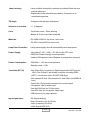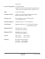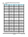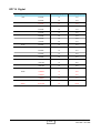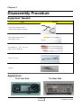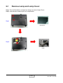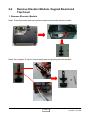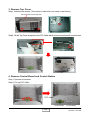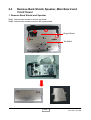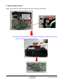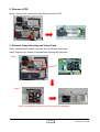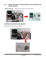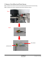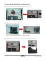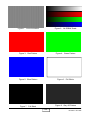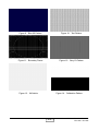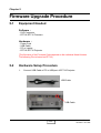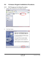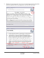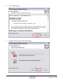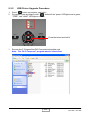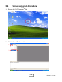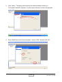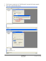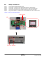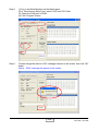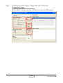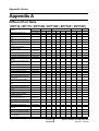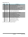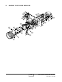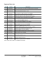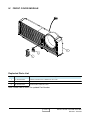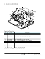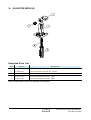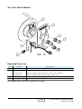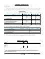
1
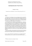
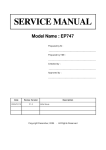
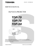
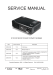
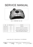
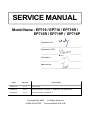
SERVICE MANUAL
Model Name : EP719 / EP716 / EP719R /
EP716R / EP719P / EP716P
Prepared by SI :
________________________________________
Prepared by TSE :
________________________________________
Checked by :
________________________________________
Approved by :
________________________________________
D a te
Version
Descrip tio n
2005/7/4
V 1 .0
Initial Issue
2005/8/9
V 2 .0
Revise Preface, C hapter 1, Appendix A & Appendix B
2006/5/29
V 3 .0
Revise Preface, Appendix A
Copyright May, 2006 . All Rights Reserved
P/N#36.82G03.002 . Document#82G-G04-01B
Preface
This manual is applied to EP719 / EP716 DMD serial projection system. The manual
gives you a brief description of basic technical information to help in service and maintain the
product.
Your customers will appreciate the quick response time when you immediately identify
problems that occur with our products. We expect your customers will appreciate the service
that you offer them.
This manual is for technicians and people who have an electronic background. Please
send the product back to the distributor for repairing and do not attempt to do anything that is
complex or is not mentioned in the troubleshooting.
The Main Difference please refer to Appendix A for Different Part Table.
Notice:
The information found in this manual is subject to change without prior notice. Any
subsequent changes made to the data herein will be incorporated in future edition.
EP719/EP716 serial Service Manual
Copyright May, 2006
All Rights Reserved
Manual Version 2.0
EP719 / EP716 / EP719R / EP716R /
I
EP719P / EP716P
Table of Contents
Chapter 1
Chapter 2
Chapter 3
Chapter 4
Chapter 5
Introduction
1-1
Product Highlights
Compatible Modes (Analog & Digital)
1-1
1-5
Disassembly of Procedure
2-1
Equipment Needed
Appearance
Remove Lamp and Lamp Cover
Remove Elevator Module, Keypad Board and Top Cover
Remove Back Shield, Speaker, Main Board and Front Cover
Remove Lamp Driver, LVPS, Thermal Sensor Board & Lamp Module
Remove Engine, Thermal Switch, Color Wheel and Photo Sensor
Remove Zoom Ring, DMD Board, Fans and Bottom Cover
2-1
2-1
2-2
2-3
2-6
2-10
2-13
2-15
Troubleshooting
3-1
Equipment Needed
LED Lighting Message
Main Procedure
3-1
3-1
3-2
Function Test and Alignment Procedure
4-1
Test Equipment
Test Condition
Test Display Modes and Pattern
Inspection Procedure
Calibration
Guide to Entering Engnineering Mode and Factory Reset
4-1
4-1
4-2
4-5
4-6
4-7
Firmware Upgrade Procedure
5-1
Equipment Needed
Hardware Setup Procedure
Firmware Progarm Installation Procedure
Firmware Upgrade Procedure
5-1
5-1
5-2
5-9
EP719 / EP716 / EP719R / EP716R /
I
EP719P / EP716P
Chapter 6
Appendix
EDID Key-in Procedure
6-1
Equipment Needed
Setup Procedure
EDID Key-in Procedure
6-1
6-2
6-3
Appendix A
7-1
Different Part Table (EP716 & EP719)
7-1
Appendix B
7-2
Exploded Overview
7-2
Appendix C
7-25
I. Serial Number System Definition
II. PCBA Code Definition
Reader’s Response
7-25
7-26
7-27
III
EP719 / EP716 / EP719R / EP716R /
EP719P / EP716P
Chapter 1
Introduction
1-1
Product Highlights
-
One panel 0.55" DMD XGA projection system with 1800 ANSI lumens (EP719)
One panel 0.55" DMD SVGA projection system with 1500 ANSI lumens (EP716)
Philips 180W UHP Lamp dimmable (Eco Mode) to 150W (EP719)
Philips 200W UHP Lamp dimmable (Eco Mode) to 150W (EP716)
High efficiency cooling system with system acoustic noise Level
Light weight Approx. 5.0 lbs.
Manual focus projection, 1:1.10 zoom lens
True 1024 x 768 resolution, 16.7M True colors (EP719)
True 800 x 600 resolution, 16.7M True colors (EP716)
With Front, Rear, Desktop, and Celling Mount Projection mode
Build-in full screen NTSC/PAL/SECAM video capability with S-video
/ Composite / Component and HDTV terminals
SXGA/XGA/SVGA/VGA/MAC compatibility.
Auto image re-sizing to 1024 x 768 full screen (EP719)
Auto image re-sizing to 800 x 600 full screen (EP716)
Auto detection of computer signal input
Auto Image synchronization (Auto-tracking /frequency /position adjustment)
Powerful enlarge and freeze function
Automatically saves adjustments for future use
On-screen menuwith 11 languages
Built-in one speaker with 2 Watt amplifier
Self protect timer for hot re-stike of UHP lamp
Adaptive voltage control fan speed
Dimensions (WxHxD)
- 230 mm x 210 mm(include focus ring and I/O connector) x
95 mm (include feet and stick handle)
Weight
- Approx. 5.0 lbs.
Cooling System
- Advanced air flow
- Two fans with low system acoustic noise level
- Temperature control circuits with adaptive voltage control
fan speed
- Maximum touch temperature follows UL 60950
EP719 / EP716 / EP719R / EP716R /
1-1
EP719P / EP716P
Lamp housing
- Lamp could be changed by customer, but should follow the user
manual instruction
- Replaceable Lamp should be provided by Coretronic or its
authorized angencies
Tilt Angle
- 6 degrees with elevator mechanism
Keystone correction
- +/- 15 degrees
Color
- Top & back cover : Silver painting
- Bottom & Front cover, black materials
Materials
- PC+ABS C6200 for top cover / rear cover
- PC 950 or Norly N225 for front cover
Lamp Door Protection
- Lamp power supply shut off automatically when door opens
Power Supply
- Universal AC 100 -- 240V ~ 50 / 60 Hz with PFC input
- 200W for Philips Lamp @ normal operation
- Variance FAN speed control (Depend on temperature variance)
Power Consumption
- 265 Watt +/- 10% at normal operation
- Standby mode < 15W
Terminals (EP719)
- One 29-pin DVI-I connector for Digital signal with HDCP(only for
USA). One D-Sub 15-pin female connector for analog RGB /
HDTV / com ponent video / SCART RGB Sync
- One separate D-Sub 15p connector for 2nd VGA in (for EMEA &
Asia)
- One D-Sub 15-pin female connector for monitor output
- One phone Jack for audio input
- One Mini DIN 4-pin for S-Video Input
- One RCA Jack for Composite Video Input
- USB connector for page up/down
Input signal spec.
- PC Signal (analog)
- Hsync Frequency 31.35~80 kHz
- Vsync Frequency 56-85 Hz
- Video Signal RGB (PC)
EP719 / EP716 / EP719R / EP716R /
1-2
EP719P / EP716P
Analog RGB 0.7Vp-p, 75 ohm
Analog RGB 1Vp-p, 75 ohm, Sync. Signal
Separate TTL H,V Sync.
Composite TTL Sync.
- Video
- Composite video 1Vp-p, 75 ohm
- S-video Luminance 0.714Vp-p, 75 ohm
- Chrominance 0.286Vp-p, 75 ohm
System Controller
- TI DDP2000
Video Compatibility
- Standards
NTSC:M(3.58MHz), 4.43MHz
PAL: B, D, G, H, I, M, N
SECAM: B, D, G, K, K1, L
HDTV: 480i/p, 576i/p, 720p, 1080i
XGA / Compression
- By using “DDP2000” Chips to compress SXGA image into
XGA display
Control Key Pad
- Power / Standby
- Directional keys (UP/DOWN/RIGHT/LEFT keys)
- Enter, Source (LEFT key), Menu
Wireless Remote
Controller
- Power on (off)
- Re-Sync,
- DVI-D
- VGA, S-Video
- Composite
- Volume +, Volume - Vertical keystone correction (UP and Down key)
- Directional keys (UP / dwon / left / right)
- Hide, Freeze
- Menu, D-zoom
- Page up, Page down (EP719)
-Display Mode (EP716)
Indicator
- “Lamp” Red
- “Temp” Red
EP719 / EP716 / EP719R / EP716R /
1-3
EP719P / EP716P
- “Power”Green
On-Screen Display Menu - 11 languages selection
English, French, German, Italian, Spanish, Norwegian, Russian,
Traditional Chinese, Simplified Chinese, Japanese, Korea
Audio
- One 8 ohm 2W speaker
Panel Spec (EP719)
- TI DMD,0.55” 12 degree DDR XGA Digital Mirror Device
- Number of active dots : 1024(H) x 768(V)
Projection Lens
- F# 2.7 - [email protected], f=21.83~23.81mm @2.36m.
1.10 x Manual Zoom Lens
Projection Image Size
- Adjustable from 34.67” to 254.22” (Diagonal)
Throw Distance
- Suggested throw distance: 1.5~10m (Optical Performance)
1.5~12m(Mechanical travel)
Brightness (EP719)
- 1530 ANSI Lumens (Typical)
- 1200 ANSI Lumens (Minimum)
Brightness (EP716)
- 1300 ANSI Lumens (Typical)
- 1000 ANSI Lumens (Minimum)
Contrast
- 1500:1 Typical
- 1000:1 Minimum
Uniformity
- 85% Marketing (Japan standard)
- 75% Typical (Japan standard)
- 60% Minmum (Japan standard)
(Full on / full off)
(Full on / full off)
EP719 / EP716 / EP719R / EP716R /
1-4
EP719P / EP716P
1-2
Compatible Modes(Analog & Digital)
EP719 Analog
Compatibility
Resolution
V-Sync[Hz]
H-Sync[KHz]
VGA
640x350
70
31.5
640x350
85
37.9
640x400
85
37.9
640x480
60
31.5
640x480
72
37.9
640x480
75
37.5
640x480
85
43.3
720x400
70
31.5
720x400
85
37.9
800x600
56
35.2
800x600
60
37.9
800x600
72
48.1
800x600
75
46.9
800x600
85
53.7
1024x768
60
48.4
1024x768
70
56.5
1024x768
75
60.0
1024x768
85
68.7
1152x864
70
63.8
1152x864
75
67.5
1152x864
85
77.1
1280x1024
60
63.98
1280x1024
75
79.98
SXGA+
1400x1050
60
63.98
MAC LC13"
640x480
66.66
34.98
MAC II 13"
640x480
66.68
35
MAC 16"
832x624
74.55
49.725
MAC 19"
1024x768
75
60.24
MAC
1152x870
75.06
68.68
MACG4
640x480
60
31.35
i Mac DV
1024x768
75
60
i Mac DV
1152x870
75
68.49
i Mac DV
1280x960
60
60
SVGA
XGA
SXGA
EP719 / EP716 / EP719R / EP716R /
1-5
EP719P / EP716P
EP719 Digital
Compatibility
Resolution
V-Sync[Hz]
H-Sync[KHz]
VGA
640x350
70
31.5
640x350
85
37.9
640x400
85
37.9
640x480
60
31.5
640x480
72
37.9
640x480
75
37.5
640x480
85
43.3
720x400
70
31.5
720x400
85
37.9
800x600
56
35.2
800x600
60
37.9
800x600
72
48.1
800x600
75
46.9
800x600
85
53.7
1024x768
60
48.4
1024x768
70
56.5
1024x768
75
60.0
1024x768
85
68.7
1152x864
70
63.8
1152x864
75
67.5
1152x864
85
77.1
1280x1024
60
63.98
1400x1050
60
63.98
SVGA
XGA
SXGA
SXGA+
EP719 / EP716 / EP719R / EP716R /
1-6
EP719P / EP716P
EP716 Analog
Compatibility
Resolution
V-Sync[Hz]
H-Sync[KHz]
VGA
640x350
70
31.5
640x350
85
37.9
640x400
85
37.9
640x480
60
31.5
640x480
72
37.9
640x480
75
37.5
640x480
85
43.3
720x400
70
31.5
720x400
85
37.9
800x600
56
35.2
800x600
60
37.9
800x600
72
48.1
800x600
75
46.9
800x600
85
53.7
1024x768
60
48.4
1024x768
70
56.5
1024x768
75
60.0
1024x768
85
68.7
1152x864
70
63.8
1152x864
75
67.5
1280x1024
60
63.98
1280x960
60
60.0
MAC LC13"
640x480
66.66
34.98
MAC II 13"
640x480
66.68
35
MAC 16"
832x624
74.55
49.725
MAC 19"
1024x768
75
60.24
MAC
1152x870
75.06
68.68
MACG4
640x480
60
31.35
i Mac DV
1024x768
75
60
i Mac DV
1152x870
75
68.49
SVGA
XGA
SXGA
EP719 / EP716 / EP719R / EP716R /
1-7
EP719P / EP716P
Chapter 2
Disassembly Procedure
Equipment Needed
Ite m
P h o to
L o n g N o s e N i p p e r (L e ft)
A ngle C utting N i p p e r (R i g ht)
H e x S le e v e s 5 m m ( To p )
S c r e w B i t (-) 1 0 1
S c r e w B i t (+) : 1 0 7 , 1 0 2 , 1 0 1
(fro m To p to Bottom)
W rench (8mm)
Nipper
Appearance
The Front Side
The Rear Side
EP719 / EP716 / EP719R / EP716R /
2-1
EP719P / EP716P
2-1
Remove Lamp and Lamp Cover
Step1: Turn unit facedown, unscrew two screws to remove Lamp Cover.
Step2: Unscrew two screws to pull out Lamp Module.
Step1
Lamp Cover
Step2
Lamp
EP719 / EP716 / EP719R / EP716R /
2-2
EP719P / EP716P
2-2
Remove Elevator Module, Keypad Board and
Top Cover
1. Remove Elevator Module
Step1: Push the elevator and unscrew two screws to remove the elevator module.
Step2: Use a nipper To clip out a small spring and a long spring front the elevator.
EP719 / EP716 / EP719R / EP716R /
2-3
EP719P / EP716P
Step 3: Use the bottom side of nipper to push down the tenon to separate elevator.
Step4: Unscrew one screw to remove the top of elevator.
Step5: Push down to separate the body of elevator.
Step 3
Step 4
step 5
2. Remove Rear Cover
Step1: Unscrew six screws
Step2: Pull open from the edge of the rear cover
Step3: Detach rear cover from the bottom side.
(As the picture shows)
Rear Cover
EP719 / EP716 / EP719R / EP716R /
2-4
EP719P / EP716P
3. Remove Top Cover
Step1: Unscerw five screws. (Two screws in each side, one screw in the bottom)
There are two screws this side.
Step2: Lift the Top Cover and pull out the FPC Cable which connect main board & control board.
4. Remove Control Board and Control Botton
Step 1: Unscrew four screws.
Step 2: Pull up FPC Cable.
FPC Cable
Control Board
Control Botton
EP719 / EP716 / EP719R / EP716R /
2-5
EP719P / EP716P
2-3
Remove Back Shield, Speaker, Main Board and
Front Cover
1. Remove Back Shield and Speaker
Step1: Unscrew two screws to remove top shield.
Step2: Unscrew two screws to remove the engine shield.
Engine Shield
Top Shield
EP719 / EP716 / EP719R / EP716R /
2-6
EP719P / EP716P
Step3: Unscrew four screws and unplug one wire to remove back shield.
There is still a screw in this side
2
1
3
4
NOTE: When you remove the back shield, you have to detach it from the top .(As
the picture show)
Step4: Unscrew four screw to remove speaker
from back shield.
EP719 / EP716 / EP719R / EP716R /
2-7
EP719P / EP716P
2. Remove Main Board
Step5: Unscrew two screws and unplug nine wires to remove main board.
Note: Main board and DMD is connected by a connector, in order to remove main
board, you have to pull up and remove it.
EP719 / EP716 / EP719R / EP716R /
2-8
EP719P / EP716P
3. Reomve Front Cover
Step1: Loose two screws to pull out the front cover.
Step2 : Unscrew two screws to remove IR sensor lens and IR sensor board.
Step1:
Step2:
Note: To remove the IR lens from front cover, you have to use a tool to push the
tenon of the lens as the picture shows.
longer
shorter
IR lens
IR senser
Front cover
Note : The longer side of IR lens is near to the top cover.
The shorter side of IR lens is near to the bottom cover.
EP719 / EP716 / EP719R / EP716R /
2-9
EP719P / EP716P
2.4
Remove Lamp Driver, LVPS, Thermal Sensor
Board and Lamp Module
1. Remove Lamp Driver
Step1: Unscrew two screws and unplug three wires to remove the lamp driver module from main
body.
Note : The lamp driver doesn’t have the error proof function, when you compose the
projector , be sure to put it back in right direction.
Step2 : Unscrew four screws to separate lamp driver and lamp driver holder
EP719 / EP716 / EP719R / EP716R /
2-10
EP719P / EP716P
2. Remove LVPS
Step1: Unscrew four screws and three wires to remove LVPS
3. Remove Lamp Housing and Lamp Fans
Step1: Unscrew three screws to remove fan module from main body.
Step2: Unscrew four screws to separate lamp housing and lamp fans.
Step 1
Step 2
Note: Do not push the center of fan, it is easy to be damaged.
EP719 / EP716 / EP719R / EP716R /
2-11
EP719P / EP716P
Step3: Unscrew one screw to remove thermal sensor board.
step4: Unscrew two scerws to remove interrupt switch.
Step5: Unscrew two screws to remove lamp wire.
Step5 (lamp wire)
Step3
sensor board
Step4 (interrupt swithch)
Thermal sensor board
lamp wire
interrupt switch
EP719 / EP716 / EP719R / EP716R /
2-12
EP719P / EP716P
2-5
Remove Engine, Thermal Switch, Color Wheel and
Photo Sensor
1.Remove Engine -- Unscrew five screws to remove engine.
2. Remove Thermal Switch and Light Cut
Step1: Unscrew one screw to remove thermal switch.
Step2: Unscrew one screw to remove light cut.
EP719 / EP716 / EP719R / EP716R /
2-13
EP719P / EP716P
3. Remove Color Wheel and Photo Sensor
Step1: Unscrew one screw to remove color wheel and photo sensor from main body.
Step2: Unscrew one screw to separate color wheel and photo sensor.
Step1
Step2
color wheel
photo sensor
EP719 / EP716 / EP719R / EP716R /
2-14
EP719P / EP716P
2.6
Remove ZoomRing, DMD Board, Fans and Bottom
Cover
1. Remove Zoom Ring -- Unscrew two screws to remove zoom ring.
2. Remove DMD Board
Step1: Unscrew four screws to remove spring plate and heat sink.
Step2: Unscrew four hex screws to remove DMD Board and separate DMD module.
EP719 / EP716 / EP719R / EP716R /
2-15
EP719P / EP716P
3. Remove Blower Fan Module and Bottom Cover
Step1: Unscrew three screws to remove blower fan from bottom cover.
Step2: Separate fan and blower rubber.
Note: Do not press the center of fan, it is easy to damaged.
Step3: There are four tenons, pull them to separate the bottom shield and bracket.
EP719 / EP716 / EP719R / EP716R /
2-16
EP719P / EP716P
Chapter 3
Troubleshooting
Equipment Needed
-
PC or pattern generator
DVD player (Video, S-Video, Audio)
Quantum Data 802B or CHROMA 2327
After changing parts, check the below information.
Charge Parts/Update
Version Update
Color Wheel Index ADC Calibration Video Calibration
M/B
v
v
v
FW
v
v
v
Color Wheel
Reset Lamp
Use Time
Factory Reset
EDID
v
v
v
v
v
v
Lamp Module
v
LED Lighting Message
Message
S t a n d b y S ta te
( In p u t p o w e r c o r d )
Power LED
(G re e n )
Te m p L E D
Lamp LED
F la s h i n g
L a m p li g h ti n g
Power on
P o w e r o f f ( C o o li n g )
E r r o r ( L a m p fa i l)
E r r o r ( T h e r m a l fa i l)
E r r o r ( F a n f a i l)
F la s h i n g
E r r o r ( O v e r Te m p . )
E rro e
(L a m p B re a k d o w n )
Steady light --->
No light
--->
EP719 / EP716 / EP719R / EP716R /
3-1
EP719P / EP716P
Main Procedure
No Power
-
Ensure that the power cord and AC power outlet are securely connected.
Check Lamp Cover and Interrupt Switch
Ensure that all connectors are securely connected and aren’t broken.
Check DC-DC
Check Ballast
Check Main Board
Auto Shut Down
-
Check LED Status
a. Lamp LED light
- Check Lamp
- Check Lamp Driver
- Check Main Board
b. Temp LED Light
- Check Thermal Sensor
- Check Thermal Switch
- Check Fan
c. Color Wheel
- Check color wheel
- Photo sensor
d. No Power
- Refer to “No Power” troubleshooting
No Image
-
-
Ensure that the signal cables and source are work as well. (If you connect
multiple sources at the same time, use the “Source” button on the control
panel to switch.)
Ensure that all connectors are securely connected and aren’t broken.
Check Main Board
Check DMD Board
Check Color Wheel
Check DMD Chip
Check Engine Module
EP719 / EP716 / EP719R / EP716R /
3-2
EP719P / EP716P
No Light on
-
Ensure that all connectors are securely connected and aren’t broken.
Check Lamp Module
Check DC-DC
Check Ballast
Check Main Board
Mechanical Noise
-
Check Color Wheel
Check Fan Module
Line Bar/Line Defect
-
Sometimes it’s because of DMD chip and DMD board did not assemble
properly
Check DMD Board
Check DMD Chip
Check Main Board
Image Flicker
-
Do “Reset” of the OSD Menu.
Ensure that the signal cables and source are work as well.
Check Lamp Module
Check Color Wheel
Check DMD Board
Check Main Board
Color Abnormal
-
Do “Reset” of the OSD Menu.
Adjust Color Wheel Index
Check Main Board
Check DMD Board
Check Color Wheel
Poor Uniformity/Shadow
-
Ensure the projection screen without dirt.
Ensure the projection lens is clean.
Ensure the Brightness is within spec.
(Replace the Lamp if the Brightness is less than spec.)
Check Engine Module
EP719 / EP716 / EP719R / EP716R /
3-3
EP719P / EP716P
Dead Pixel/Dust (Out of spec.)
-
Ensure the projection screen without dirt
Ensure the projection lens is clean
Clean DMD Chip and Engine Module
Check DMD Chip
Check Engine Module
Garbage Image
-
Ensure that the signal cables and source work as well.
Check Main Board
Check DMD Board
Remote Controllor or Control Panel Failed
-
-
Remote Control
a. Check Battery
b. Check Remote Controller
c. IR receiver
Control Panel
a. Check FPC
b. Check keypad
c. Check Main Board
Function Abnormal
-
Do “ Reset” of the OSD menu
Check Main Board
Check DMD board
EP719 / EP716 / EP719R / EP716R /
3-4
EP719P / EP716P
Chapter 4
Function Test & Alignment Procedure
4-1
Test Equipment
-
4-2
IBM PC with XGA resolution (Color Video Signal & Pattern Generator)
DVD player with Multi-system (NTSC/PAL/SECAM)
HDTV Tuner or Source (480p, 720p, 1080i), equipped with “S-Video”,
“Component”, “Composite” interface.
Minolta CL-100
Quantum Data 802B or CHROMA2327
Test Condition
-
Circumstance Brightness : Dark room less than 2.5 lux.
Inspection Distance : 1.5m~3m for functional inspection
Screen Size : 60 inches diagonal (wide)
After repairing each EP719, the unit should be burn-in (Refer to the table
below).
Symptom
Burn-in Time
Normal Repair
2 Hours
NFF
4 Hours
Auto Shutdown
6 Hours
EP719 / EP716 / EP719R / EP716R /
4-1
EP719P / EP716P
4-3
Test Display Modes & Pattern
Function Test Display Pattern
Item
Test Content
Pattern
Specification
Remark
1
Frequency & Tracking
Fine Line Moire
Eliminate visual wavy noise by
Rsync, Frequency or Tracking
selection.
Figure 1
2
Contrast/Brightness
64 RGBW scale
Gray level should be
distinguishable and without color
abnormal.
Figure 2
3
R, G, B and White Color R, G, B and White
Performance
Color
Each R, G, B color should be
normal without color abnormal
issue.
Figure 3~6
4
Screen Uniformity
Should be compliant with
60%.(Minimum)
Figure 6
Dead Pixel (Bright pixel) Full Black
Cannot accept any bright pixel
Figure 7
Dead Pixel (Dark pixel)
Full White
The numbers of dead pixel should
be smaller or amount to 6 pixel.
Figure 8
6
Blemish (Bright)
The bright blemish cannot be
Full Black / Gray 30 accepted if the problem appear
with Gary 30 pattern.
7
Blemish (Dark)
Full white / Blue 60
The dark blemish cannot be
accepted if the problem appear
with Blue 60 pattern.
Figure 6,9
8
Focus
Text Pattern
The text in the corner should be
clear after adjust the focus ring.
Figure 10
9
Boundary
Boundary Frame
Horz. And Vert. position of video
should be adjustable to be the
screen frame.
Figure 11
10
Light Leak
Gray 10
The unit can't accept the leakage is
Figure 12
brighter than Gray 10 pattern
11
HDTV
94% White
No discolor
Figure 13
12
ADC Calibration
(PC Calibration)
Calibration Pattern
Calibration Pattern should be in full
screen mode
Figure 14
5
Full White
Figure 7, 8
EP719 / EP716 / EP719R / EP716R /
4-2
EP719P / EP716P
Figure 1. Fine Line Moire
Figure 2. 64 RGBW Scale
Figure 3. Red Pattern
Figure 4. Green Pattern
Figure 5. Blue Pattern
Figure 6. Full White
Figure 7. Full Black
Figure 8. Gary 30 Pattern
EP719 / EP716 / EP719R / EP716R /
4-3
EP719P / EP716P
Figure 9. Blue 60 Pattern
Figure 10. Text Pattern
Figure 11. Boundary Frame
Figure 12. Gary 10 Pattern
Figure 13. 94%white
Figure 14. Calibration Pattern
EP719 / EP716 / EP719R / EP716R /
4-4
EP719P / EP716P
4-4
Inspection Procedure
-
Frequency and Tracking
Test Signal : 1024x768@60Hz
Test Pattern : Line Moire Pattern
*
Check and see if image sharpness and focus are well performed.
*
If not, readjust by following steps.
(1) Select “Frequency” function to adjust the total pixel number of pixel
clock in one line period.
(2) Then select “Tracking” function and use right or left arrow key to adjust
the value to minimize video flicker.
-
Boundary
Test Signal : 1024x768@60Hz
Test Pattern : Boundary Frame
*
Adjust Resync or Frequency/Tracking/H. Position/V. Position to the inner of
the screen.
-
Focus
Test Signal : 1024x768@60Hz
Test Pattern : Text Pattern
*
Adjust the center clearly, meanwhile, one slightly vague corner in the image is
allowed
-
HDTV
Equipment : Quantum Data 802B or CHROMA 2327
Test Signal : 480p, 702P, 1080I
Test Pattern : Color Bar
If the test result was discoloration or flickering, please return the unit back to the
repair center.
-
Color Performance
Test Signal : 1024x768@60Hz
Test Pattern : 64 RGBW scale Pattern and Gray 16 Pattern
*
Please check and ensure if each color is normal and distinguishable
*
If not,please adjust color index of the service mode.
EP719 / EP716 / EP719R / EP716R /
4-5
EP719P / EP716P
-
Screen Uniformity
Test Signal : 1024x768@60Hz
Test Pattern : Full White Pattern
*
Please check and ensure the unit is under the spec.
*
Please check and see if it’s in normal condition.If not, please return the unit to
repair area.
*
Please check and see if there are dead pixels on DMD chip
*
The total numbers and distance of dead pixels should be complaint with the
spec.
-
Light Leak
Test Signal : 1024x768@60Hz
Test Pattern : Gray 10 Pattern
*
Please check and see if the light leaks*Notice
*
The unit cannot accept the leakage is brighter than Gary 10 pattern
Notice : light leak on reflective edge, eyecatcher, bond wires and exposed metal.
4-5
Calibration
-
-
Once Main Board is changed, firmware upgrade should be done as well.
Video Calibration
Test Signal : HDTV Signal (720p)
Test Pattern : Calibration Pattern (Figure 13)
Get into service mode to select video calibration.
ADC Calibration (PC Calibration)
Test Signal : 1024x768@60Hz
Test Pattern : Calibration Pattern (Figure 14)
* Calibration Pattern should be in full screen mode, white above and black below.
Note:
1. Refer to the above Calibration’s test signal.
2. Please refer to the follwoing steps for entering service mode.
3. Choose and access video calibration & ADC calibration for correction in service
mode. Choose “Exit” to leave the service mode after all.
EP719 / EP716 / EP719R / EP716R /
4-6
EP719P / EP716P
-
Dead Pixel (Bright/Dark pixel)
Test Signal : 1024x768@60Hz
Test Pattern : Full Black Pattern and Full White Pattern
(1) Bright Pixel :
Test Pattern : Full Black Pattern
-Please check and ensure that the unit cannot accept any
bright pixel.
-If not, please return the unit to repair area.
(2) Dark Pixel :
Test Pattern : Full White Pattern
-Please check and ensure that the pixel number should be smaller
or amount to 6 pixels
-If not, please return the unit to repair area.
4-6
Guide to Entering Service Mode and Factory Reset
-
Service Mode
Please do the following steps to enter service Mode.
Turn on the power and wait for the disappearance of Logo picutre.
press “Power” button, “
(source) “, “
(source)“, “Menu” button
sequentially to enter Service Mode Menu.
-
Factory Reset
After final QC step, we have to erase all saved change again and restore the factory defaults.
Please enter the service mode, and then choose “Factory Reset” then choose
“YES” and press enter to see if it works.
This action will allow you to erase all end-user’s settings and restore the original
setting.
EP719 / EP716 / EP719R / EP716R /
4-7
EP719P / EP716P
Chapter 5
Firmware Upgrade Procedure
5-1
Equipment Needed
Software :
- DLP Composer
- EP719 /EP716 Firmware
Hardware :
-
Power Cord
USB Cable
PC or Laptop
EP719 /EP716 Projector
(The file name of the Firmware Code depends on the individual Model Version.
The following Pics is based on EP719.)
5-2
Hardware Setup Procedure
1.
Connect USB Cable of PC to USB port of EP719 Projector.
USB Cable
USB Cable
EP719 / EP716 / EP719R / EP716R /
5-1
EP719P / EP716P
5-3
Firmware Progarm Installation Procedure
5-3.1
DLP Composer Lite Setup Procedure
1.
Choose “DLP Composer Lite v3.6 Setup” program.
2.
Click “Next” button.
EP719 / EP716 / EP719R / EP716R /
5-2
EP719P / EP716P
3.
Reading the “License Agreement” rules, choose “I accept and agree to be bound by all the
terms and conditions of this License Agreement” icon, then click “Next” button.
1
2
3
EP719 / EP716 / EP719R / EP716R /
5-3
EP719P / EP716P
4.
Click “Next”button.
5.
Choose “All” icon, then click “Next” button.
1
2
EP719 / EP716 / EP719R / EP716R /
5-4
EP719P / EP716P
6.
Click “Next” button.
7.
The program is executing “Initializing” status.
EP719 / EP716 / EP719R / EP716R /
5-5
EP719P / EP716P
5-3.2
1.
2.
USB Driver Upgrade Procedure
Press “
“ button on projector, and hold it.
Plug power code and keep to hold “
“ button till the “power “LED light turns to green,
“TEMP”, and “LAMP” LED light turn to red.
Press the button and hold it
3.
Execute the C:\Program files\DLP Composer\usbupdata.cmd.
Note : The “DLP Composer” program must be closed first.
EP719 / EP716 / EP719R / EP716R /
5-6
EP719P / EP716P
4.
Type any key to continue. Then wait about a minute.
5.
Click “OK”. The USB driver updated successfully.
EP719 / EP716 / EP719R / EP716R /
5-7
EP719P / EP716P
6.
Right click “My Computer” on the desktop. Select “Properties” on the popup menu to
launch the “System Properties” window. Choose “Hardware” and then click “Device
Manager.”
7.
Click “Jungo” to assure “DDP2000” and “WinDriver” are properly installed. If not, repeat
Step 1 ~ 6.
Device Manager
EP719 / EP716 / EP719R / EP716R /
5-8
EP719P / EP716P
5-4
Firmware Upgrade Procedure
1.
Execute the “DLP ComposerTM” file.
2.
Click “Edit” and “Preferences”.
1
2
EP719 / EP716 / EP719R / EP716R /
5-9
EP719P / EP716P
3.
Click “Library”. The library path located to the default installation directory is :
C:\Program Files\DLP Composer. If not then press “Browse” to select the right path.
1
2
4.
Select “Edit\Preferences\Communications”, choose “USB”, and then click “OK”.
1
2
EP719 / EP716 / EP719R / EP716R /
5-10
EP719P / EP716P
5.
(1) Choose “Flash Loader”
(2) Click “Browse” to serach the “EP719_Flash_A03.img” file.
(3) select the item “Skip Boot Loader Area(load all but the first 16KB)”.
(4) Click “Reset Bus” to erase the flash memory
1
2
3
4
Note : If appears the error message “cannot open USB driver - No projectors found”.
Please unplug the USB cable and replug, then do step (4) again.
EP719 / EP716 / EP719R / EP716R /
5-11
EP719P / EP716P
7.
8.
If the firmware is ready, then click “Start Download” to process the firmware upgrade.
Click “Yes” to erase the flash memory.
8
7
EP719 / EP716 / EP719R / EP716R /
5-12
EP719P / EP716P
9.
After file was download. EP719 will be back to standby status automatically (Power LED
flash green). Please to restart the unit and enter the Service mode to check the F/W
version of EP719 . Note
Note : How to into Service Mode:
step 1. Turn on the power and wait for the disappearance of Logo picutre.
step 2. Do the following action sequentially to enter Service Mode Menu
(1) press”power” botton (2) press “ (source)” botton twice
(3) press “menu” button
EP719 / EP716 / EP719R / EP716R /
5-13
EP719P / EP716P
Chapter 6
EDID Key-in Procedure
6-1
Equipment Needed
-
PC or Laptop
EDID Fixture
Power Adapter
RS-232 Cable (Female to Male)
VGA Cable
DVI Cable
Power Cord
DDC Driver
EP719 / EP716 Unit
RS-232 Cable (F-M)
VGA Cable
Power Adapter
EDID Fixture
DVI Cable
EP719 / EP716 / EP719R / EP716R /
6-1
EP719P / EP716P
6-2
Setup Procedure
Step1.
Step2.
Step3.
Step4.
Step5.
Connect Power Adapter with the fixture.
Connect P1 of the fixture with COM1 of PC/Laptop by RS232 cable.
Connect P2 of the fixture with VGA port of EP719 / EP716 by VGA cable.
Connect P3 of the fixture with DVI Port of EP719 / EP716 by DVI cable
Plug Power Adapter to the fixture and connect the EP719 / EP716 Power Cord.
*Notice : Confirm JP3 is “Close” status.
Power Adapter
JP3
P1
P2
P3
marked as “Generic”
DVI Port VGA port
EP719 / EP716 / EP719R / EP716R /
6-2
EP719P / EP716P
6-3
EDID Key-in Procedure
Step 1.
Execute “EDID” program.
Step 2.
(1) Check the Com port is “COM1”
(2) Click the “Model” item
(3) Choose the source file “OPTOMA_EP719EDID_A.ini” and then open it.
EP719 / EP716 / EP719R / EP716R /
6-3
EP719P / EP716P
Step 3.
(1) Key in the Serial Number into the blank space.
(2) In “Write Source Select” Item, select “VGA” and “DVI” both.
(3) Check the COM port is COM1
(4) Click “Program” button.
1
4
2
3
Step 4.
“Please change the cable to VGA” message is shown on the screen, then click “OK”
button.
Notice : “RUN” message will appear on the screen.
EP719 / EP716 / EP719R / EP716R /
6-4
EP719P / EP716P
Step 5.
“Please change the cable to DVI” message is shown on the screen, then click “OK”
button”.
Step 6.
When the EP719 EDID program is finish, the “OK” message will appear on the
screen.
EP719 / EP716 / EP719R / EP716R /
6-5
EP719P / EP716P
Step 7.
(1) Make sure to check “Analog” , ”Digital” and “Trans” in Read item
(2) press “Read” button.
(3) EDID Informations will show the result.
(4) Click “Reset” to do the next unit or “Exit” button to close the EDID program.
2
3
4
1
EP719 / EP716 / EP719R / EP716R /
6-6
EP719P / EP716P
Appendix Series
Appendix A
Different Part Table
(EP716 / EP719 / EP716R / EP719R / EP716P / EP719P)
Description
Area
P/N
SCREW PAN MECH M3*5 Ni
85.1A123G050
SCREW PAN MECH M3*5 Ni
85.1A123.050
SCREW HEX I/O #4-40 H4*L8 NI
NYLOK
SCREW HEX I/O #4-40 H4xL8 Ni
Nylok
BACK COVER PC MN3600H EP716R
85.005AGG408
51.82G04G072
42.82G02G003
CABLE FFC 14P 100mm EP719
42.82G02G001
TOP COVER PC+ABS C6200 EP716
51.82G01G021
PCBA MAIN BOARD EP719ER
80.82G10G002
PCBA MAIN BOARD EP719AR
80.82G10G001
PCBA MAIN BOARD EP719 EUROP
80.82G01G004
PEBAG ZIPPER #3 100*70*0.04 LMT5020
PE BAG 380(L)*310(W)*0.07mm
LABEL FOR IO CONNECTOR EP719
(EUROPE)
LABEL FOR IO CONNECTOR EP716
LABEL FOR IO CONNECTOR RS232
EP716R
LABEL FOR IO CONNECTOR RS232
EP719 (AMERICA)
V
V
V
V
V
V
V
V
V
V
V
V
V
V
V
V
V
V
V
V
V
V
51.82G04G021
80.82M01G001
INFRARED REMOTE CONTROL
W/DVI BUTTON EP719
INFRARED REMOTE CONTROL
W/2nd VGA BUTTON EP719
PE BAG 21PPER 280*200*0.04 #9
Mexico
Europe
V
51.82G04G062
PCBA MAIN BOARD EP716
EP716 USER GUIDE (CD)
V
51.82G04G001
TOP COVER PC+ABS C6200 EP7190
51.82G01G001
"GREEN'
DMD 800*600 PIXEL DDR FTP 0.55"
48.859DMGD13
SVGA
DMD 1024*768 PIXEL DDR FTP 0.55"
48.82GDMGD01
XGA
PCBA MAIN BOARD EP716
80.82M01G002
USER'S GUIDE MULTILINGUAL (CD)
EP716R
EP719 USER GUIDE (CD)
Taiwan
85.005AG.408
BACK COVER PC+ABS C6200
EP7190
BACK COVER PC MN3600H
EP719AR/EP719ER
BACK COVER PC+ABS C6200
EP716
FFC Cable 14P 100mm EP719
CABLE POWER CORD 1830mm SP023+IS14 EUR.
CABLE POWER CORD 1830MM
SP30+IS14 "GREEN"
CABLE POWER CORD 1830mm
(BSMI)
CABLE POWER CORE 11m EP732H
America
EP716R EP719R EP719 EP716 EP716P EP719P EP716R EP719R EP716MX
V
V
V
V
V
V
V
V
V
V
V
V
V
V
V
V
V
V
V
V
V
V
V
V
V
V
V
V
V
V
V
V
V
V
V
V
V
V
42.50112.001
42.50115G001
V
V
V
V
V
42.50115G004
V
V
V
V
42.80V06.001
36.82M01G002
V
V
V
36.82G01G001
V
V
V
V
36.82M01G001
V
45.82G01.001
45.82G01.002
V
V
V
V
V
51.80136G001
V
V
V
V
V
V
V
V
51.52121.001
51.00174G001
V
V
V
35.82G01G011
35.82G05G001
V
V
V
V
35.82G01G021
35.82G06G011
V
V
V
V
V
7-1
V
V
EP719 / EP716 / EP719R / EP716R /
EP719P / EP716P
Appendix Series
Appendix B
Exploded Overview
I.
EP719 Unit
7-2
EP719 / EP716 / EP719R / EP716R /
EP719P / EP716P
Exploded Parts List
Item
Part No
Description
1
51.82G05G001
LAMP COVER NORYL N300 EP7190 "GREEN"
2
61.80511.001
SCREW PAN MECH M3*8-4 BLACK
3
61.81105.001
NUT PLATE SUS 0.5t EzPro 610
4
61.82G25G001
EMI SHIELDING FRONT PLATE AL 0.3t EP7190 "GREEN"
5
61.82G28G001
LAMP COVER AL FOIL 0.1t EP719 "GREEN"
6
70.82G01G001
ASSY BOTTOM HOUSING MODULE EP7190 "GREEN"
7
70.82G02G001
ASSY FRONT COVER MODULE EP7190
8
70.82G03G001
ASSY BACK COVER MODULE EP7190
9
70.82G04G001
ASSY TOP COVER MODULE EP7190 "GREEN"
10
70.82G09G001
ASSY LAMP MODULE EP7190
11
70.82G12G001
ASSY ENGINE MODULE EP7190 "GREEN"
12
70.82G18G001
ASSY AXIAL FAN MODULE EP7190 "GREEN"
13
70.82G19G001
ASSY LAMP DRIVER MODULE EP7190
14
70.82G20G001
ASSY EMI GROUND PLATE MDULE EP719
15
75.82G07G001
BUY ASSY EMI FRONT PLATE EP719
16
80.82G01G001
PCBA MAIN BOARD EP719 "GREEN"
17
85.005AG.408
SCREW HEX I/O #4-40 H4xL8 Ni NYLOK
18
85.1A123.050
SCREW PAN MECH M3*5 NI
Note: Please refer to RSPL for updated Part Number.
7-3
EP719 / EP716 / EP719R / EP716R /
EP719P / EP716P
II.
ENGINE TOP COVER MODULE
7-4
EP719 / EP716 / EP719R / EP716R /
EP719P / EP716P
Exploded Parts List
Item
Part No
Description
1
11.009F0G005
CNNT F 166P FOR 0.55" SVGA LGA DMD SOCKET;FOXCONN
2
23.82G01G001
ALL SPHERICAL GLASS 1.10 ZOOM LENS YO
3
48.82GDMGD01
DMD 1024X768 PIXEL DDR 0.7" XGA
4
51.80B31G001
DMD INSULATOR MYLAR .8t 3300MP
5
51.82G06G001
FOCUS RING PC+ABS C6200 EP7190 "GREEN"
6
51.82G07G001
ZOOM RING PC+ABS C6200 EP7190 "GREEN"
7
51.82G08G001
ZOOM RING ORBIT PC+ABS C6200 EP7190 "GREEN"
8
51.82G21G001
FOCUS RING LIGHTCUT MYLAR EP7190 "GREEN"
9
51.82G22G001
ZOOM ANTI-ABRASION TEFLON EP7190 "GREEN"
10
52.82G03G002
RELAY SEALED RUBBER-2 EP719
11
52.82G10G001
RELAY CUSHION RUBBER EP7190 "GREEN"
12
52.87130G001
RUBBER BLOWER 595925 "GREEN"
13
52.87319G001
DMD THERMAL PAD 18*13*0.5t "GREEN"
14
52.89627G002
DMD SEAL RUBBER BF1000 3.2t EP719
15
61.80J48G001
DMD HEATSINK BACKER PLATE 739 AL6061 "GREEN"
16
61.82G02G001
ENGINE TOP COVER Mg Alloy-AZ91D EP7190
17
61.82G05G001
DMD HEATSINK AL EP7190 "GREEN"
18
61.88608G001
DMD HEATSINK SPRING PLATE SUS301 0.4t Ivy10X
19
61.88611G001
DMD SCREW Ivy10X "GREEN"
20
61.89643G001
DMD MASK PLATE SUS301 0.15t EP759
21
80.82G02G001
PCBA DMD BOARD EP7190
22
85.1A123.050
SCREW PAN MECH M3*5 NI
23
85.1A123.060
SCREW PAN MECH M3*6 Ni
24
85.YA321G051
SCREW FLAT HEAD TAP M1.7*5 BLACK
Note: Please refer to RSPL for updated Part Number.
7-5
EP719 / EP716 / EP719R / EP716R /
EP719P / EP716P
III. BOTTOM HOUSING MODULE
Exploded Parts List
Ite m
P a rt N o
D e s c rip tio n
1
5 1 .8 2 G 0 2 G 0 0 1
B O TTO M C O V E R P C + A B S C 6 2 0 0 E P 7 1 9 0
2
5 1 .8 2 G 1 6 G 0 0 1
ELEVATOR FOOT PC+ABS C6200 DP725
3
5 2 .8 9 6 0 1 .0 0 1
A D JUST FOOT RUBBER EP759
4
7 0 .8 2 G 0 6 G 0 0 1
A S S Y B A S E P L ATE M O D U L E E P 7 1 9 0
5
7 0 .8 2 G 0 7 G 0 0 1
A S S Y E L E VATOR MODULE EP7190
6
8 5 .1 A 3 2 6 .0 6 0
S C R E W P A N H E A D M E C H M 2 .6 * 6 B L A C K
7
8 5 .4 A 3 2 6 .0 6 0
S C R E W P A N H E A D M E C H M 2 .6 * 6 B L A C K
8
8 6 .0 A 5 2 3 .0 4 0
H E X N U T W /M Y L O N M 3 * 0 .5 L 4 .0 W H IT E
Note: Please refer to RSPL for updated Part Number.
7-6
EP719 / EP716 / EP719R / EP716R /
EP719P / EP716P
IV. FRONT COVER MODULE
Exploded Parts List
Item
Part N o
Descrip tion
1
51.82G03G001
FRONT COVER PC+ABS6410 EP7190
2
51.82G09G001
IR LENS FRONT PC EP7190
3
80.82G05G001
P C B A IR BD FOR EP7190
Note: Please refer to RSPL for updated Part Number.
7-7
EP719 / EP716 / EP719R / EP716R /
EP719P / EP716P
V.
TOP COVER MODULE
Exploded Parts List
Ite m
P a rt N o
D e s c rip tio n
1
42.82G02G001
CABLE FFC 14P 100mm EP719
2
42.82G02G001
TOP C O V E R P C + A B S C 6 2 0 0 E P 7 1 9 0
3
52.82G01G001
K E YPA D L E D L E N S R U B B E R E P 7 1 9 0 " G R E E N "
4
80.82G03G001
P C B A K E YPA D B O A R D E P 7 1 9 " G R E E N "
5
8 5 .1D 1 2 2 .040
S C R E W P A N M E C H M 2 *4 Ni (W /WA S H E R D 5 .0)
Note: Please refer to RSPL for updated Part Number.
7-8
EP719 / EP716 / EP719R / EP716R /
EP719P / EP716P
V.
BASE PLATE MODULE
Exploded Parts List
Ite m
P a rt N o
D e s c rip tio n
1
51.82G24G001
L A M P D R IV E R IN S U L A M Y L A R E P 7 1 9 0
2
51.85816.001
L IM IT S W ITC H H O L D E R P P S X B 3 1
3
51.85824.001
L IM IT S W ITC H B O T T O M H O L D E R P P S X B 3 1
4
52.88504.001
THE R M A L PA D 2 1 *26*3t F O R L V P S
5
61.82G01G001
B A S E P L ATE M g A llo y A Z 9 1 D E P 7 1 9 0
6
70.82G08G001
A S S Y LV P S M O D U L E E P 7 1 9 0 " G R E E N "
7
70.82G17G001
ASSY BLOWER FAN MODULE EP7190 "GREEN"
8
75.88514.002
A S S Y LIM IT S W ITC H C H E R R Y D B 3 C A 1 L B -5A
9
76.82G01G001
B U Y A S S Y W.A . 2 P 1 5 0 m m L V P S / L A M P E P 7 1 9
10
80.82G04G001
P C B A THE R M A L S E N S O R B O A R D E P 7 1 9 0
11
85.1A123.050
S C R E W P A N M E C H M 3 *5 NI
12
85.1A126.040
S C R E W P A N M E C H M 2 .6*4 Ni
13
85.3A122.040
S C R E W C A P M E C H M 2 *4 Ni
Note: Please refer to RSPL for updated Part Number.
7-9
EP719 / EP716 / EP719R / EP716R /
EP719P / EP716P
VI. ELEVATOR MODULE
Exploded Parts List
Ite m
P a rt N o
D e s c rip tio n
1
51.82G15G001
E L E VATOR P U S H P C + A B S C 6 2 0 0 E P 7 1 9
2
5 1 . 8 6 8 0 9 .0 0 1
E L E VATOR B O D Y NYL O N + G F D P 7 2 5
3
51.86810G071
E L E VATOR HOLD E R P C + A B S C 6 2 0 0 E P 7 1 9 0
4
6 1 . 8 5 9 1 3 .0 0 1
E L E VATOR S P R IN G S U S 3 0 4 S B 2 1
5
6 1 . 8 6 8 1 4 .0 0 1
E L E VATOR S P R IN G S U S 3 0 4 S B 2 1
Note: Please refer to RSPL for updated Part Number.
7-10
EP719 / EP716 / EP719R / EP716R /
EP719P / EP716P
VII. LVPS MODULE
Exploded Parts List
Ite m
P a rt N o
D e s c rip tio n
1
4 2 .81G01.001
W .A . 2 P # 2 0 1 6 0 m m L A P S /B A L L A S T H 3 1
2
4 2 .88502.002
W .A . 1 4 P 1 3 0 m m L V P S T O M /B 2 2 0 0 M P
3
51.82G19G001
L V P S L E A D W IN D P C M Y L A R E P 7 1 9 0
4
75.81J01.003
A S S Y LV P S Q U A S A R 2 0 0 W E P 7 3 9 /H31
Note: Please refer to RSPL for updated Part Number.
7-11
EP719 / EP716 / EP719R / EP716R /
EP719P / EP716P
VIII. Color Wheel Module
Exploded Parts List
Ite m
P a rt N o
D e s c rip tio n
1
23.82G19G001
R 9 2 G 8 3 B 7 5 W 1 1 0 C O L O R W H E E L "G R E E N
2
5 2 . 8 3 6 1 5 .0 0 1
C O L O R W H E E L D IS C R U B B E R , E z P r o 7 5 5
3
61.82G10G001
C O L O R W H E E L H O L D E R S E C C 1 .2t E P 7 1 9 0 " G R E E N "
4
6 1 . 8 3 6 2 8 .0 0 1
C O L O R W H E E L SHOULD E R S C R E W , E zPro755
5
80.82G06G001
PCBA PHOTO SENSOR BOARD EP719
6
8 5 . 1 A 6 2 6 .0 4 0
S C R E W P A N M E C H M 2 .6*4 BLACK NYLON
Note: Please refer to RSPL for updated Part Number.
7-12
EP719 / EP716 / EP719R / EP716R /
EP719P / EP716P
IX. BLOWER FAN MODULE
Exploded Parts List
Ite m
P a rt N o
D e s c rip tio n
1
49.82G01G001
M IS C B L O W E R 4 5 * 2 0 " G R E E N " ; D E LTA
2
52.82G08G001
BLOWER 4520 RUBBER EP7190 "GREEN"
Note: Please refer to RSPL for updated Part Number.
7-13
EP719 / EP716 / EP719R / EP716R /
EP719P / EP716P
X.
AXIAL FAN MODULE
Exploded Parts List
Item
Part No
Description
1
49.80N01.001
SUNON 70*20 R-TYPE AXIAL FAN
2
75.82G04G001
BUY ASSY 7020 FAN BRACKET EP719
3
85.1F123.260
SCREW PAN MECH E/SF M3x26 Ni
Note: Please refer to RSPL for updated Part Number.
7-14
EP719 / EP716 / EP719R / EP716R /
EP719P / EP716P
XI. LAMP DRIVER
Exploded Parts List
Item
Part N o
Description
1
42.82G01G001
W.A . 5P #28 200mm LAMP DRIV E R TO MAIN BD EP719 "GREEN"
2
51.82G17G001
LAMP DRIV E R HOLD E R PC+ABS C6200
3
51.82G23G001
LAMP DRIV E R INSULA MYLAR EP7190
4
75.88501.001
A S S Y PHILIPS LAMPDRIV E R 2200MP
5
85.WA123.060
.SCREW PAN TAP M3*6 Ni
Note: Please refer to RSPL for updated Part Number.
7-15
EP719 / EP716 / EP719R / EP716R /
EP719P / EP716P
XII. PACKING PROCEDURE DRAWING
7-16
EP719 / EP716 / EP719R / EP716R /
EP719P / EP716P
Exploded Parts List
Ite m
P a rt N o
D e s c rip tio n
1
PART NO.
D .C . E P 7 1 9
2
4 2 .5 0 1 1 5 .0 0 1
C A B L E P O W E R C O R D 1 8 3 0 m m S P 3 0 + IS 1 4
A K .8 2 G 0 1 G 0 0 A
A .K . E P 7 1 9 A M E R IC A
3
3 5 .8 2 0 0 1 .111
L A B E L C A RTON 3"x3" B L A N K P J 8 8 5
4
3 6 .0 0 0 1 8 .0 0 1
E X T E N D W A R R A N TY;R E G IS T R A T IO N F R O M ,US A
5
3 6 .8 0 A 0 1 .0 0 1
S A F E TY & W A R R A N TY G U ID E , M U L T IL IN G U A L H 3 0
6
3 6 .8 2 G 0 1 G 0 0 1
E P 7 1 9 U S E R G U ID E (C D )
7
3 6 .8 2 G 0 2 G 0 0 1
E P 7 1 9 Q U IC K S TA R T G U ID E
8
4 2 .8 7 2 0 5 .0 0 1
C A B L E C O M P O S IT E V ID E O 1 .8 M 3 2 0 0 M P
9
4 2 .8 7 3 0 5 .0 0 1
C A B L E V G A 1 5 P 1 .8 M B L K 2 1 0 0 M P
10
4 5 .8 2 G 0 1 .0 0 1
R E M O T E C O N T R O L W / D V I B U TTO N E P 7 1 9
11
4 6 .8 0 3 0 1 .0 0 1
B A T T E R Y # 4 1 .5 V
12
5 1 .8 0 1 3 6 .0 0 1
P E B A G ZIP P E R 2 8 0 x 2 0 0 x 0 . 0 4 # 9
D P.8 2 G 0 1 G 0 0 1
D .P. E P 7 1 9
13
5 1 .8 6 7 2 6 .0 0 1
OPTOMA LOGO EP731
14
5 3 .8 2 G 0 1 .0 0 1
S O F T C A R R Y B A G F O R E P 7 1 9 /E P 7 1 6
15
7 5 .8 2 G 0 3 G 0 0 1
BUY ASSY LENS CAP MODULE EP719
16
5 5 .8 2 G 0 1 G 0 0 1
C A R T O N O U S ID E B F L U T E E P 7 1 9
17
5 6 .8 2 G 0 1 G 0 0 1
C U S H IO N E P E R IG H T E P 7 1 9
18
5 6 .8 2 G 0 2 G 0 0 1
C U S H IO N E P E L E F T E P 7 1 9
19
5 1 .0 0 1 7 4 G 0 0 1
P E B A G 4 5 0 * 3 5 0 * 0 .0 7 L M T-5 0 2 0
20
5 7 .0 0 0 0 1 G 0 0 1
P A C K S IO 2 D R IE R 2 0 g " G R E E N "
21
3 5 .8 1 4 0 6 .0 0 1
L A B E L S P E C 3 2 * 1 0 6 B L A N K E zP r o 7 1 0
22
3 5 .8 2 0 0 1 .111
L A B E L C A RTON 3"x3" B L A N K P J 8 8 5
23
5 8 .8 6 2 0 1 G 0 0 1
W O O D P A L L E T 4 8 " * 4 0 * 5 " ( D O U B L E F A C E ) "G R E E N "
24
5 8 .8 6 2 0 2 G 0 0 1
C O V E R P A L L E T 1 2 4 0 * 1 0 2 0 m m F O R E zP r o 7 3 6 " G R E E N "
Note: Please refer to RSPL for updated Part Number.
7-17
EP719 / EP716 / EP719R / EP716R /
EP719P / EP716P
EP716 Unit
7-18
EP719 / EP716 / EP719R / EP716R /
EP719P / EP716P
Exploded Parts List
Item
Part No
Description
1
51.82G05G001
LAMP COVER NORYL N300 EP7190 "GREEN"
2
61.80511.001
SCREW PAN MECH M3*8-4 BLACK
3
61.81105.001
NUT PLATE SUS 0.5t EzPro 610
4
75.82G07G001
BUY ASSY EMI FRONT PLATE EP719
5
61.82G28G001
LAMP COVER AL FOIL 0.1t EP719 "GREEN"
6
70.82G01G001
ASSY BOTTOM HOUSING MODULE EP7190 "GREEN"
7
70.82G02G001
ASSY FRONT COVER MODULE EP7190
8
70.82M07G001
ASSY BACK COVER MODULE EP716
9
70.82M06G001
ASSY TOP COVER MODULE EP716
10
70.82G09G001
ASSY LAMP MODULE EP7190
11
70.82M02G001
ASSY ENGINE MODULE EP716
12
70.82G18G001
ASSY AXIAL FAN MODULE EP7190 "GREEN"
13
70.82G19G001
ASSY LAMP DRIVER MODULE EP7190
14
70.82G20G001
ASSY EMI GROUND PLATE MDULE EP719
15
75.82G07G001
BUY ASSY EMI FRONT PLATE EP719
16
80.82M01G001
PCBA MAIN BOARD EP716
17
85.005AG.408
SCREW HEX I/O #4-40 H4xL8 Ni NYLOK
18
85.1A123.050
SCREW PAN MECH M3*5 NI
19
85.5A323.060
SCREW BIN MECH M3*6 Black
19
61.00079G001
GROUNDING CABLE CLAMP FN-008 "PINGOOD
Note: Please refer to RSPL for updated Part Number.
7-19
EP719 / EP716 / EP719R / EP716R /
EP719P / EP716P
EP716 Assy Engine Module
Exploded Parts List
Item
Part No
Description
1
70.82G13G001
ASSY ENGINE BOTTOM COVER MODULE EP7190
2
70.82M03G001
ASSY ENGINE TOP MODULE EP716
3
85.1A123.050
SCREW PAN MECH M3*5 Ni
Note: Please refer to RSPL for updated Part Number.
7-20
EP719 / EP716 / EP719R / EP716R /
EP719P / EP716P
EP716 Engine Top Cover Module
7-21
EP719 / EP716 / EP719R / EP716R /
EP719P / EP716P
Exploded Parts List
Item
Part No
Description
1
11.009F0G005
CNNT F 166P FOR 0.55" SVGA LGA DMD SOCKET;FOXCONN
2
23.82G01G002
PROJECTION LENS BARREL CHA
3
48.859DMGD13
DMD 800*600 PIXEL DDR FTP 0.55" SVGA
4
51.80B31G001
DMD INSULATOR MYLAR .8t 3300MP
5
51.82G06G001
FOCUS RING PC+ABS C6200 EP7190 "GREEN"
6
51.82G07G001
ZOOM RING PC+ABS C6200 EP7190
7
51.82G08G001
ZOOM RING ORBIT PC+ABS C6200 EP7190 "GREEN"
8
51.82G21G001
FOCUS RING LIGHTCUT MYLAR EP7190 "GREEN"
9
51.82G22G001
ZOOM ANTI-ABRASION TEFLON EP7190 "GREEN"
10
52.82G03G002
RELAY SEALED RUBBER-2 EP719
11
52.82G10G001
RELAY CUSHION RUBBER EP7190 "GREEN"
12
52.87130G001
RUBBER BLOWER 595925 "GREEN"
13
52.87319G001
DMD THERMAL PAD 18*13*0.5t "GREEN"
14
52.89627G002
DMD SEAL RUBBER BF1000 3.2t EP719
15
61.80J48G001
DMD HEATSINK BACKER PLATE 739 AL6061 "GREEN"
16
61.82G02G001
ENGINE TOP COVER Mg Alloy-AZ91D EP7190
17
61.82G05G001
DMD HEATSINK AL EP7190 "GREEN"
18
61.88608G001
DMD HEATSINK SPRING PLATE SUS301 0.4t Ivy10X
19
61.88611G001
DMD SCREW Ivy10X "GREEN"
20
61.89643G001
DMD MASK PLATE SUS301 0.15t EP759
21
80.82G02G001
PCBA DMD BOARD EP7190
22
85.1A123.050
SCREW PAN MECH M3*5 NI
23
85.1A123.060
SCREW PAN MECH M3*6 Ni
24
85.YA321G051
SCREW FLAT HEAD TAP M1.7*5 BLACK
Note: Please refer to RSPL for updated Part Number.
7-22
EP719 / EP716 / EP719R / EP716R /
EP719P / EP716P
EP716 Assy Top Cover Module
Exploded Parts List
Ite m
P a rt N o
D e s c rip tio n
1
4 2 .8 2 G 0 2 G 0 0 1
CABLE FFC 14P 100mm EP719
2
5 1 .8 2 G 0 1 G 0 2 1
TOP COVER PC+ABS C6200 EP716
3
5 2 .8 2 G 0 1 G 0 0 1
K E YPA D L E D L E N S R U B B E R E P 7 1 9 0 " G R E E N "
4
8 0 .8 2 G 0 3 G 0 0 1
P C B A K E YPA D B O A R D E P 7 1 9 " G R E E N "
5
8 5 .1 D 1 2 2 .0 4 0
S C R E W P A N M E C H M 2 *4 Ni (W / W A S H E R
6
4 1 .8 2 G 0 5 G 0 0 1
EMI GASKET W10*L20*H3mm EP719
7
5 1 .8 1 5 4 1 G 0 0 1
TA P E 3 M J 3 5 0 1 7 * 3 0 m m
D 5 .0 )
Note: Please refer to RSPL for updated Part Number.
7-23
EP719 / EP716 / EP719R / EP716R /
EP719P / EP716P
EP716 Assy Back Cover Module
Exploded Parts List
Ite m
P a rt N o
D e s c rip tio n
1
35.82G01G021
L A B E L F O R IO C O N N E C T O R E P 7 1 6
2
51.82G04G021
BACK COVER PC+ABS C6200 EP716
3
51.82G10G001
IR L E N S R E A R P C E P 7 1 9 0
Note: Please refer to RSPL for updated Part Number.
7-24
EP719 / EP716 / EP719R / EP716R /
EP719P / EP716P
Appendix Series
Appendix C
I. Serial Number System Definition
Serial Number Format for Projector
A BBB Y WW C D BEMO EEEE
1
2
3
4
5
6
7
1
:
A = Optoma, B~Z = OEM
2
:
Product code (ex: 82G = EP719 ; 82M =EP716)
3
:
Y = Last number of the year (ex: 2004 - 4)
4
:
Week of year
5
:
Panel vendor code
6
:
Electrical classification (1=110V, 2=220V, 0=universal)
7
:
B = BIOS version, E = PCB board version,
8
M = Mechanical version, O = Optical version
8
:
Serial code (from 0001~)
EX : A82G429T0AAAA1001
This label “A82G429T0AAAA1001” represents the whole serial number for EP719,
including Ver. 1st of BIOS and Ver. 1 of PCB Board. Both mechanical and optical version
are 1st. In addition, panel vendor is T0. It’s produced on 29s-week of 2004 for universal
area and its serial code is 1001.
7-25
EP719 / EP716 / EP719R / EP716R /
EP719P / EP716P
II. PCBA Code Definition
PCBA Code for Projector
A B XXXXXXXXXX C XXX EEEE
1
3
2
1
:
ID
2
:
Vendor Code
3
:
P/N
4
:
Revision
5
:
Date Code
6
:
S/N
4
5
6
C: M/B
B: DMD/ B
7-26
EP719 / EP716 / EP719R / EP716R /
EP719P / EP716P
*Reader’s Response*
Dear Readers:
Thank you for your backing our service manual up. In order to refine our content of the
service manual and satisfy your requirement. We expect you can offer us some precious opinions for reference.
Assessment:
A.
What do you think about the content after reading EP719 / EP716 Service Manual?
Unit
Excellent
Good
Fair
Bad
1. Introduction
2. Disassembly Procedure
3. Troubleshooting
4. Function Test & Alignment Procedure
5. Firmware Upgrade Procedure
6. DDC key-in Procedure
7. Appendix
B.
Are you satisfied with the EP719 / EP716 service manual?
Item
Excellent
Good
Fair
Bad
1. Service Manual Content
2. Service Manual Layout
3. The form and listing
C.
Do you have any other opinion or suggestion about this service manual?
Reader’s basic data:
Name:
Title:
Company:
Add:
Tel:
Fax:
E-mail:
After your finishing this form, please send it back to Coretronic Customer Service
Dept. by fax: 886-3-563-5333.
7-27
EP719 / EP716 / EP719R / EP716R /
EP719P / EP716P