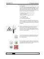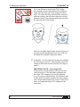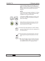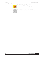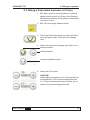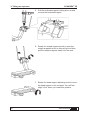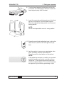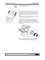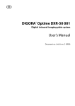
1
ENGLISH
SCANORA® 3D
Cone Beam 3D Imaging System
User’s Manual
202044 rev. 10 (2010-11)
SCANORA® 3D
SCANORA® 3D
Cone Beam 3D Imaging System
User’s Manual
Medical Device Directive
93/42/EEC
Number 202044 rev. 10 (2010-11)
Original approved English language version
Manufactured by SOREDEX
Nahkelantie 160,Tuusula
P.O. BOX 148
FI-04301 Tuusula,
Finland
Tel. +358 (0)45 7882 2000
Fax. + 358 9 701 5261
User’s Manual 202044
iii
SCANORA® 3D
Soredex endeavours to produce product documentation that is accurate and
up to date. However, our policy of continual product development may result in
changes to products that are not reflected in the product documentation. Therefore, this document should not be regarded as an infallible guide to current product specifications. Soredex maintains the right to make changes and alterations
without prior notice.
iv
User’s Manual 202044
SCANORA® 3D
Contents
ENGLISH................................................................................................................. 1
1. Introduction........................................................................................................ 1
1.1 The SCANORA® 3D ................................................................................... 1
1.2 Intended use .............................................................................................. 2
1.3 About this manual....................................................................................... 3
1.4 Abbreviations used in this manual.............................................................. 4
1.5 Associated documentation ......................................................................... 4
1.6 About cone beam 3D imaging .................................................................... 4
2. The SCANORA® 3D ............................................................................................ 5
2.1 Main parts and controls .............................................................................. 5
2.2 The control panel ....................................................................................... 8
3D display ................................................................................................ 8
Panoramic display (OPTIONAL) .............................................................. 8
2.3 Remote control ........................................................................................... 9
2.4 Patient positioning lights .......................................................................... 10
3D lights ................................................................................................. 10
Panoramic lights (OPTIONAL) .............................................................. 10
2.5 Imaging programs .....................................................................................11
3D programs ...........................................................................................11
Scout programs ..................................................................................... 12
Panoramic programs (OPTIONAL) ........................................................ 13
2.6 Positioning devices .................................................................................. 14
3. Taking an exposure ......................................................................................... 15
3.1 Preparing the system ............................................................................... 15
3.2 Taking a 3D exposure .............................................................................. 16
3.3 Taking a Panoramic exposure (OPTIONAL) ............................................ 29
3.4 After use ................................................................................................... 39
4. Messages and error codes ............................................................................. 40
4.1 Messages ................................................................................................. 40
4.2 Error codes............................................................................................... 42
User’s Manual 202044
v
SCANORA® 3D
5. System Settings............................................................................................... 43
5.1 Unit Settings ............................................................................................. 43
Opening the Settings window ................................................................ 43
The Settings .......................................................................................... 43
Information button .................................................................................. 44
Language button .................................................................................... 44
5.2 Software settings...................................................................................... 44
6. Quality assurance............................................................................................ 45
6.1 The 3D QA procedure .............................................................................. 45
Starting the QA procedure. .................................................................... 45
Geometry calibration ............................................................................. 49
Pixel calibration ..................................................................................... 51
Quality Check ........................................................................................ 53
6.2 The Panoramic QA procedure (OPTIONAL) ............................................ 57
7. Care, maintenance and disposal .................................................................. 61
7.1 Cleaning and disinfecting the unit ............................................................ 61
Unit surfaces and upholstery ................................................................. 61
Positioning light covers .......................................................................... 61
Surfaces that the patient touches .......................................................... 61
7.2 Checking that the unit operates correctly ................................................. 62
General observations ............................................................................ 62
Quality assurance check ....................................................................... 62
Emergency stop knob ............................................................................ 62
Yearly maintenance ............................................................................... 62
7.3 Disposal .................................................................................................. 63
7.4 Symbols that appear on the unit .............................................................. 64
8. Warnings and precautions ............................................................................. 66
8.1 To be observed during use ....................................................................... 66
8.2 General warnings ..................................................................................... 69
Appendix A. Technical Data...............................................................................A-1
A.1 Technical specifications ..........................................................................A-1
A.2 Unit dimensions ......................................................................................A-9
A.3 Electromagnetic declaration .................................................................A-10
vi
User’s Manual 202044
SCANORA® 3D
1. Introduction
1. Introduction
1.1 The SCANORA® 3D
The SCANORA® 3D is a cone beam computerized
tomography x-ray system intended to take digital
images of the dento-maxillo-facial complex and the
head and neck areas, including the ear, nose and
throat (ENT) areas of the human skull.
The following 3D images can be taken:
-
60 x 60 mm (height x diameter) small FOV
(Field Of View), standard or high resolution
-
75 x 100 mm (height x diameter) medium FOV
standard or high resolution
-
75 x 145 mm (height x diameter) large FOV
standard or high resolution.
-
OPTIONAL: 130 x 145 mm (height x diameter)
extra large FOV standard or high resolution.
Two large 3D images are automatically taken
and then combined to form a single image.
The following scout images (a single image of the
front lateral half of the 3D images) can also be
taken:
User’s Manual 202044
-
60 x 30 mm (height x width), a front lateral image of the 60 x 60 mm 3D small FOV
-
75 x 50 mm (height x width), a front lateral image of the 75 x 100 mm 3D medium FOV
-
75 x 72.5 mm (height x width), a front lateral image of the 75 x 145 mm 3D large FOV.
Also the lower front part of the 130 x 145 mm 3D
extra large FOV.
1
SCANORA® 3D
1. Introduction
With the OPTIONAL panoramic sensor the following panoramic exposures can be taken:
-
adult panoramic,
-
child panoramic (reduced width and height)
-
lateral TMJ, left and right.
A CMOS flat panel detector is used to acquire 3D
images and an optional CCD sensor to acquire
panoramic images.
The unit is connected to a PC in which suitable
dental imaging software and 3D imaging software
have been installed. All software must conform to
the MDD and the relevant legal requirements in the
USA.
1.2 Intended use
The unit must only be used and operated by qualified healthcare professionals.
The unit must only be used to take 3D and (OPTIONAL) panoramic images of the dento-maxillofacial complex and the head and neck areas, including the ear, nose and throat (ENT) areas of the
human skull. It must not be used to take images of
any other part of the human body.
USA only
Caution: Federal law restricts this device to sale by
or on the order of a dentist or other qualified professional.
2
User’s Manual 202044
SCANORA® 3D
1. Introduction
1.3 About this manual
This manual describes how to set up and use both
versions of the SCANORA 3D x-ray unit, the 3D
version and the 3D Panoramic version.
Please read this user’s manual before operating the
unit for the first time.
CAUTION:
It is important to read the warnings and precautions, listed in section 8, before operating the
unit for the first time.
It is also important to observe these warnings
and precautions whenever the unit is used.
NOTE:
Instructions in this user’s manual starting with PC:
for example:
“1. PC: Open a new or existing patient”
indicate that the task is carried out from the PC.
Instructions NOT starting with PC: for example:
“3. Close the head supports”
indicate that the task is carried out from the UNIT.
NOTE:
Before you use the imaging system for the first
time, set the system to your requirements. See
section 5. System Settings.
User’s Manual 202044
3
SCANORA® 3D
1. Introduction
1.4 Abbreviations used in this manual
FOV = Field Of View. The cylindrical 3D volume that
the unit will take an exposure of.
ROI = Region Of Interest. The anatomical area or
region of the patient that you are interested to examine.
1.5 Associated documentation
The Scanora workstation software user’s manual.
The user’s instructions supplied with the 3D viewing
software you are using.
1.6 About cone beam 3D imaging
During a 3D exposure the tubehead rotates around
the patient’s head taking a series of 2D images of
the selected ROI, 225 to 450 depending upon the
3D program and resolution selected. The 3D imaging software then reconstructs the separate 2D images to form a 3D model (a volume) of the ROI.
4
User’s Manual 202044
SCANORA® 3D
2. The SCANORA® 3D
2. The SCANORA® 3D
2.1 Main parts and controls
User’s Manual 202044
5
2. The SCANORA® 3D
6
SCANORA® 3D
User’s Manual 202044
SCANORA® 3D
User’s Manual 202044
2. The SCANORA® 3D
7
2. The SCANORA® 3D
SCANORA® 3D
2.2 The control panel
3D display
Mode buttons
FOV buttons
Resolution /
scout buttons
mA buttons
End study
button
Settings button
Information window
Test exposure button
Panoramic display (OPTIONAL)
Program buttons
kV buttons
mA buttons
8
User’s Manual 202044
SCANORA® 3D
2. The SCANORA® 3D
2.3 Remote control
User’s Manual 202044
9
2. The SCANORA® 3D
SCANORA® 3D
2.4 Patient positioning lights
3D lights
Panoramic lights (OPTIONAL)
10
User’s Manual 202044
SCANORA® 3D
2. The SCANORA® 3D
2.5 Imaging programs
3D programs
60 x 60 mm (diameter x height) small FOV.
Standard resolution (voxel size 0.20 mm) or high
resolution (voxel size 0.133 mm).
75 x 100 mm (height x diameter) medium FOV.
Standard resolution (voxel size 0.30 mm) or high
resolution (voxel size 0.20 mm).
75 x 145 mm (height x diameter) large FOV.
Standard resolution (voxel size 0.35 mm) or high
resolution (voxel size 0.25 mm).
130 x 145 mm (height x diameter) extra large FOV.
Standard resolution (voxel size 0.35 mm) or high
resolution (voxel size 0.25 mm).
User’s Manual 202044
11
2. The SCANORA® 3D
SCANORA® 3D
Scout programs
60 x 30 mm (height x width) scout projection image.
Allows the position of the 60 x 60 mm 3D small FOV
to be verified.
The program takes a single lateral image of the
front half of the 60 x 60 mm FOV program.
75 x 50 mm (height x width) scout projection image.
Allows the position of the 75 x 100 mm 3D medium
FOV to be verified.
The program takes a single lateral image of the
front half of the 75 x 100 mm FOV program.
75 x 72.5 mm (height x width) scout projection image.
Allows the position of the 75 x 145 mm 3D large
FOV to be verified.
The program takes a single lateral image of the
front half of the 75 x 145 mm FOV program.
Also allows the position of the OPTIONAL 130 x 145
3D extra large FOV to be verified.
The program takes a single lateral image of the front
lower half of the 130 x 145 mm FOV program.
12
User’s Manual 202044
SCANORA® 3D
2. The SCANORA® 3D
Panoramic programs (OPTIONAL)
Adult panoramic. Magnification 1.25
Child panoramic. Magnification 1.25
Lateral temporomandibular joints.
Magnification 1.25
User’s Manual 202044
13
2. The SCANORA® 3D
SCANORA® 3D
2.6 Positioning devices
Chin cup
Disposable cover
Bite block
Disposable cover
Lip holder
Disposable cover
Lip support
Disposable cover
14
User’s Manual 202044
SCANORA® 3D
3. Taking an exposure
3. Taking an exposure
3.1 Preparing the system
1. PC: Switch the PC on.
IMPORTANT NOTE:
Make sure that the hardware key (dongle) is
connected to the PC. If a hardware key has
been removed the system will not work correctly.
Note that some systems have two hardware
keys.
2. Switch the unit on. The on/off switch is on the
under side of the electronics cabinet.
A message will appear on the control panel asking you to press and hold the chair down button
to complete unit start up.
CAUTION: Crushing Danger!
Before pressing the chair down button remove
all objects, for example drawers, wheel chairs,
stools etc., from around the chair to avoid damage to the unit or injury to people.
3. Press and hold the chair down key until the unit
stops moving.
A message will then appear asking you to select
a patient and then start image capture.
The system is now ready to take an exposure.
User’s Manual 202044
15
SCANORA® 3D
3. Taking an exposure
3.2 Taking a 3D exposure
1. PC: Open a new or existing patient or select a
patient from the work list. Refer to the user’s
guide supplied with the Scanora Workstation
software for information on how to do this.
NOTE:
Do not open the 3D viewing software.
2. PC: Click the Image Capture button. The image
capture window will open.
3. Touch the 3D button to select the 3D program
mode.
4. Select the Field Of View (FOV):
60 x 60 mm small FOV
75 x 100 mm medium FOV
75 x 145 mm large FOV
130 x 145 mm extra large FOV
NOTE:
For the 130 x 145 mm extra large FOV the
unit will take two large FOV images and then
combine them to form a single extra large FOV
image.
16
User’s Manual 202044
SCANORA® 3D
3. Taking an exposure
5. Select the scout image or the 3D resolution:
Scout image
Standard resolution 3D image
High resolution 3D image
IMPORTANT NOTE:
Take a scout image before taking the 3D image
if you wish to check that the Region Of Interest
(ROI) is in the correct position within the FOV.
6. Select the mA.
CAUTION:
When taking an exposure of a child use the lowest possible mA (8 - 10 mA recommended) that
will allow you to perform the required diagnostic
task.
7. Slide the forehead support into the two holes
in the chin rest and then push the locking lever
down to lock the forehead support in position.
User’s Manual 202044
17
SCANORA® 3D
3. Taking an exposure
Release the head strap.
8. Rotate the temple supports knob to open the
temple supports as far as they will go and then
pull the temple supports away from the seat.
9. Rotate the head support adjusting knob to move
the head support to its mid point. You will feel
slight “click” when you reach this position.
10. Turn the head support lever to the left to release
the head support and then rotate the head support away from the seat to the open position.
18
User’s Manual 202044
SCANORA® 3D
3. Taking an exposure
11. Insert the chin cup into the chin rest.
NOTE:
Use a new disposable cover for every patient.
12. Press the chair down key to drive the chair down
so that it is low enough for the patient to enter
unit.
13. Ask the patient to remove any spectacles, dentures, jewellery and hair clips and pins.
Place a protective lead apron on the patient.
NOTE:
If the patient is nervous, or a child, you can
demonstrate how the unit works to reassure
them.
Touch the T (Test) button and then press and
hold the exposure button. The unit will complete
an exposure cycle without generating x-rays.
14. Press the key button to drive the rotating unit to
the 3D ready position.
User’s Manual 202044
19
3. Taking an exposure
SCANORA® 3D
15. If necessary lift up the arm rests and then ask
the patient to sit on the chair. Make sure that the
patient is sitting straight and in the middle of the
chair with their back pushed against the backrest.
Also make sure that they are sitting in a position
in which they feel comfortable.
If the patient is very large and cannot sit completely on the seat or is small and cannot sit
back far enough, adjust the forward/backward
position of the backrest with the knob at the rear
of the chair.
Also, with small patients and children use cushions to position the patient at the right height.
20
User’s Manual 202044
SCANORA® 3D
3. Taking an exposure
Wheelchair patients
Adjust the height of the unit chair so that the
seat is level with the wheelchair seat or as near
as possible at the same level.
Position the patient in the wheelchair as close
as possible to the left-hand side of the unit chair
with the patient facing forwards.
Ask the patient to put the wheelchair’s brake on
so that wheelchair cannot move.
Make sure that the left-hand arm rest of the unit
chair is in the raised position.
Manually rotate the rotating unit so that the
detector head is at the front. This will make it
easier for the patient to enter the unit.
Ask the patient to remove or lower the armrest
on the right-hand side of the wheelchair.
Ask the patient to slide from the wheelchair onto
the unit chair.
When the patient is in the unit chair lower the
left-hand chair armrest.
Remove the wheelchair from the unit environment.
NOTE:
After taking the exposure repeat the above
procedure in the reverse order to get the patient
back into the wheelchair.
16. Carefully rotate the head support towards the
patient until it stops. Turn the head support locking lever to the right to lock the head support in
position.
User’s Manual 202044
21
3. Taking an exposure
SCANORA® 3D
17. Rotate the head support positioning knob to
position the head support so that the patient can
place their chin on the chin cup or bite the bite
block.
18. Press the light key to switch the patient positioning lights on.
NOTE:
If the patient positioning lights do not come on
the rotating unit is not in the 3D ready position.
To switch the lights on, press the return key to
drive the unit to the 3D ready position and then
press the light key to switch the patient positioning lights on.
19. Press the head support up/down keys to level or
adjust the angle of the patient’s head.
20. Push the temple supports towards the patient
so that they are positioned on both sides of the
patient’s head. Carefully rotate the temple support knob to close the temple supports so that
they grip the patient’s head.
22
User’s Manual 202044
SCANORA® 3D
3. Taking an exposure
21. Press the seat height adjusting keys to position
the ROI within FOV you have selected. The upper light beam indicates top of the FOV and the
lower light beam the bottom of the FOV.
If you are taking an extra large FOV image position the lower light level with the bottom of the
patient’s chin. For an adult patient with average
size head this will place the boundary between
the two large FOV images in an area away from
the crowns.
22. The sagittal light (vertical front light) indicates
the center of the FOV in the sagittal direction.
Press the left / right field of view positioning keys
to position the sagittal light so that it is in the
center of the ROI you wish to examine.
User’s Manual 202044
23
3. Taking an exposure
SCANORA® 3D
23. The lateral light (vertical side light) indicates the
center of the FOV in the lateral direction.
Press the forwards / backwards field of view
positioning keys to position the patient so that
the lateral light in the center of the ROI you wish
to examine.
If you are taking a scout view the lateral light
indicates the left-hand edge of the scout view.
24. Slide forehead support up or down until it is positioned in front of the patient’s forehead. Wrap
the forehead support strap around the patient’s
head, slide the strap through the buckle and
then gently pull the strap to tighten it around the
patient’s head. Fold the strap backwards and
then secure it in position.
24
User’s Manual 202044
SCANORA® 3D
3. Taking an exposure
25. Tell the patient not to move for the duration of
the exposure.
If you are taking an extra large FOV (130 x 145
mm) 3D image tell the patient that TWO images
will be taken and that after the first image has
been taken the chair will automatically descend
and the unit take a second exposure.
The approximate exposure times are:
- scout, 5 seconds
- small, medium and large FOV 3D,
10 - 20 seconds.
- extra large FOV 3D
20 - 26 second exposures
Protect yourself from radiation by standing behind a suitable x-ray radiation shield. Make sure
that you can see and hear the patient during the
exposure.
26. Press and hold down the exposure button for
the duration of the exposure. During the exposure you will hear an audible signal and the
exposure warning symbol will appear on the on
the touch control panel.
If you are taking a scout image the rotating unit
will not move and the image will be taken from
the ready position
If you are taking a small, medium or large FOV
3D image the rotating unit will rotate around the
patient’s head once and then stop.
User’s Manual 202044
25
3. Taking an exposure
SCANORA® 3D
If you are taking an extra large FOV image
the rotating unit will rotate around the patient’s
head, take the first half of the image and then
stop. The chair will then automatically descend
and the rotating unit will then rotate around the
patient’s head in the opposite direction and take
the second half of the image.
When the audible signal stops and the exposure
warning symbol disappears from the touch control panel the exposure has been taken.
27. It will take 1 to 5 minutes to process and transfer
the 3D image to the PC. After transfer, open the
image window and double click the 3D image to
open it.
IMPORTANT NOTE - extra large FOV
If the patient moved between the first and second exposure or if the boundary between the
two large FOV images is not clearly defined
(e.g. too many metal artifacts), the software may
not be able to properly combine the two images
into a single extra large FOV image. If this is the
case, two separate large FOV images will be
produced.
26
User’s Manual 202044
SCANORA® 3D
3. Taking an exposure
If the boundary between the two large FOV images is not clearly defined but the software is
able to combine the two images the dimensional
accuracy across the boundary area may be
reduced.
NOTE:
If you took a scout image it will take 10 - 20 seconds for the image, a single half lateral image,
to appear on the unit control panel.
If the patient is NOT positioned correctly, touch
the OK key, reposition the patient and take another scout image.
If the patient is positioned correctly, touch the
OK key and then select the resolution you require and take the 3D image.
28. After the 3D image appears on the PC display
press the Return key to drive the rotating unit to
the ready position.
29. Drive the chair to its lowest position, open the
head support and guide the patient out of the
unit.
30. PC: The 3D image can be examined using the
3D imaging software. Refer to the documentation supplied with the 3D imaging software.
User’s Manual 202044
27
SCANORA® 3D
3. Taking an exposure
31. PC: Click the Abort Capture button when you
have taken all the necessary images,
or
32. To finish the examination touch the End study
button.
28
User’s Manual 202044
SCANORA® 3D
3. Taking an exposure
3.3 Taking a Panoramic exposure (OPTIONAL)
1. PC: Open a new or existing patient or select a
patient from the work list. Refer to the Scanora
Workstation software users guide for information
on how to do this.
2. PC: Click the Image Capture button.
3. Touch the Panoramic button to select the Panoramic program mode. The button will change
color.
4. Select the panoramic program you wish to use:
adult panoramic
child panoramic
temporomandibular joints
4. Select the kV and mA.
CAUTION:
When taking an exposure of a child use the lowest possible kV (67kV recommended) and mA
(4 - 5.3mA recommended) that will allow you to
perform the required diagnostic task.
User’s Manual 202044
29
3. Taking an exposure
SCANORA® 3D
5. Pull the forehead support locking lever up and
remove the forehead support.
6. Rotate the temple supports knob to open the
temple supports as far as they will go and then
pull the temple supports away from the seat.
7. Rotate the head support adjusting knob to move
the head support to its mid point. You will feel
slight “click” when you reach this position.
30
User’s Manual 202044
SCANORA® 3D
3. Taking an exposure
8. Turn the head support locking lever to the left
to release the head support and then rotate the
head support away from the seat.
9. Insert the required positioning device, bite block,
lip rest or lip support, into the head support.
Place the appropriate disposable cover on positioning device.
NOTE:
Use a new disposable cover for every patient.
10. Press the seat height adjusting keys to drive the
chair down so that it is low enough for the patient.
11. Ask the patient to remove any spectacles, dentures, jewellery and hair clips and pins.
Place a protective lead apron on the patient.
NOTE:
If the patient is nervous or a child, you can demonstrate how the unit works to reassure them.
Touch the T (Test) button and then press and
hold the exposure button. The unit will complete
an exposure cycle without generating x-rays.
User’s Manual 202044
31
3. Taking an exposure
SCANORA® 3D
12. Press the Return button to drive the rotating unit
to the ready position.
13. If necessary lift up the arm rests and then ask
the patient to sit on the chair. Make sure that the
patient is sitting straight and in the middle of the
chair with their back pushed against the backrest.
Also make sure that they are sitting in a position
in which they feel comfortable.
If the patient is very large and cannot sit completely on the seat or is small and cannot sit
back far enough, adjust the forward/backward
position of the backrest with the knob at the rear
of the seat.
Also, with small patients and children use cushions to position the patient at the right height.
32
User’s Manual 202044
SCANORA® 3D
3. Taking an exposure
Wheelchair patients
Adjust the height of the unit chair so that the
seat is level with the wheelchair seat or as near
as possible at the same level.
Position the patient in the wheelchair as close
as possible to the left-hand side of the unit chair
with the patient facing forwards.
Ask the patient to put the wheelchair’s brake on
so that wheelchair cannot move.
Make sure that the left-hand arm rest of the unit
chair is in the raised position.
Manually rotate the rotating unit so that the
detector head is at the front. This will make it
easier for the patient to enter the unit.
Ask the patient to remove or lower the armrest
on the right-hand side of the wheelchair.
Ask the patient to slide from the wheelchair onto
the unit chair.
When the patient is in the unit chair lower the
left-hand chair armrest.
Remove the wheelchair from the unit environment.
NOTE:
After taking the exposure repeat the above
procedure in the reverse order to get the patient
back into the wheelchair.
14. Carefully rotate the head support towards the
patient until it stops. Turn the head support locking lever to the right to lock the head support in
position.
User’s Manual 202044
33
3. Taking an exposure
SCANORA® 3D
15. Rotate the head support positioning knob to
position the head support so that the patient can
place their chin on the chin rest and bite the bite
block or press their lips against the lip holder or
lip support.
If you are using the lip holder or lip support ask
the patient to position their front teeth so that the
front edges are touching.
16. Press the light key to switch the patient positioning lights on.
NOTE:
If the patient positioning lights do not come on
the rotating unit is not in the panoramic ready
position.
To switch the lights on, press the return key to
drive the unit to the panoramic ready position
and then press the light key to switch the patient
positioning lights on again.
17. The horizontal light indicates the bottom of the
panoramic field. However, the light can also be
used to position the Frankfort plane.
Press the up seat height adjusting key and
position the patient so that the horizontal light is
approximately level with the Frankfort plane.
34
User’s Manual 202044
SCANORA® 3D
3. Taking an exposure
18. Press the head support up/down keys to adjust
the tilt of the patient’s head until the Frankfort
plane is parallel to the horizontal light.
19. Now position the patient for the exposure you
wish to take.
If you are taking a panoramic exposure press
the seat height adjusting keys and position the
patient so that the horizontal light is under the
patient’s chin. If you are taking a temporomandibular joint exposure, position the patient so
that the light is under the lower lip.
20. Check the position of the midsagittal light. If it is
not on the midsagittal plane of the patient, press
the left / right field of view positioning keys to
position the light correctly.
User’s Manual 202044
35
3. Taking an exposure
SCANORA® 3D
Make sure that the patient’s head is not turned
or tilted to one side.
21. Push the temple supports towards the patient
so that they are positioned on both sides of the
patient’s head. Carefully rotate the temple support knob to close the temple supports so that
they grip the patients head.
22. The focal trough light indicates the center of the
focal trough which is approximately 10 mm wide
at the front.
Press the forwards / backwards positioning keys
and position the focal trough light in the middle
of the patient’s upper canine.
This position is used for both panoramic and
temporomandibular joint exposures.
36
User’s Manual 202044
SCANORA® 3D
3. Taking an exposure
23. If necessary readjust the tilt of the patient’s head
until the roots of the upper and lower front incisors are within the focal trough.
Note that you may have to reposition the focal
trough slightly.
24. IMPORTANT NOTE:
When you press the exposure button to take a
panoramic exposure the panoramic sensor will
automatically rotate to the exposure position.
If, before taking an exposure, you want to check
that the sensor will not touch the patient, press
the Return key to drive the sensor to the exposure position and check its position in relation to
the patient.
For safety reasons, the chair cannot be driven
up when the panoramic sensor is in the exposure position. If you wish to drive the chair up
you must press the Return key to drive the
panoramic sensor back to the non exposure
position.
User’s Manual 202044
37
3. Taking an exposure
SCANORA® 3D
25. Ask the patient to press their tongue against the
roof of their mouth and remain still for the duration of the exposure, 15 seconds.
If you are taking a temporomandibular joint
exposure ask the patient to open or close their
mouth depending on which exposure you wish
to take.
Protect yourself from radiation by standing behind a suitable x-ray radiation shield. Make sure
that you can see and hear the patient during the
exposure.
26. Press and hold down the exposure button for
the duration of the exposure.
During the exposure you will hear an audible
signal and the exposure warning symbol on the
touch control panel will appear.
The rotating unit will rotate around the patient’s
head and then stop. When the rotating unit
stops, the exposure has been taken.
27. A preview image will appear on the unit control
panel. Touch the OK key.
28. After the image appears on the PC display press
the Return key to drive the rotating unit to the
ready position.
29. Drive the chair to its lowest position, open the
head support and guide the patient out of the
unit.
38
User’s Manual 202044
SCANORA® 3D
3. Taking an exposure
30. PC: The panoramic image can be examined using the Scanora workstation software. Refer to
the Scanora workstation software user’s
manual.
31. PC: Click the Abort Capture button when you
have taken all the necessary images.
or
32. Touch the End study button to finish the examination.
3.4 After use
When the unit is not being used rotate the head
support to the closed position and lock it in position
with the head support locking lever.
User’s Manual 202044
39
4. Messages and error codes
SCANORA® 3D
4. Messages and error codes
4.1 Messages
Dental imaging program not open.
Open dental imaging program from PC.
The Scanora Workstation software in the PC has
not been opened. Open the program to clear the
message.
NOTE:
If the unit is connected to the PC through a router,
this message indicates that the router is working but
the PC may not be working.
No Ethernet link
Check Eternet cable between unit and PC
Either the Eternet cable between the unit and
the PC is not connected or the PC has not been
switched on.
Reconnect the Ethernet cable or switch the PC on
to clear the message.
The exposure button was released during imaging.
Check the image to see if it is sufficient for the diagnostic task. If not take another image.
40
User’s Manual 202044
SCANORA® 3D
4. Messages and error codes
Reconstruction of the 3D image failed.
See if the image can be retrieved using the Retrieve
last image option. If not take another image.
NOTE:
This message will also appear if the hardware key
(dongle) used for software protection has been removed from the PC’s USB slot.
PC’s driver failed.
Switch the system off and then on again. If the message reappears, call service for help.
Examination closed before preview image(s)
could be shown
The exit button was pressed before the images
could be processed. The preview image(s) can be
retrieved from the imaging software.
PC’s driver failed for unknown reason.
Switch the system off and then on again. If the message reappears, call service for help.
User’s Manual 202044
41
4. Messages and error codes
SCANORA® 3D
Movement of the rotating unit was blocked.
The movement of the rotating unit was interrupted
during the exposure.
Determine and remove the reason for the interruption and then take another image.
Panoramic detector was moved from its correct
position.
The panoramic detector was moved during an exposure. Check the image to see if it is sufficient for the
diagnostic task. If not take another image.
4.2 Error codes
If an error code appears,
Error xx
switch the unit and PC off and then restart the unit
and PC. If the error message reappears, call service
for help.
42
User’s Manual 202044
SCANORA® 3D
5. System Settings
5. System Settings
5.1 Unit Settings
Opening the Settings window
Touch the settings button at the bottom of the main
window.
The settings window will appear.
The Settings
Display patient’s name
Allows you to select whether or not the name of the
patient appears on the unit control panel.
Display DAP value
Allows you to select whether or not the DAP (Dose
Area Product) appears on the unit control panel.
User’s Manual 202044
43
SCANORA® 3D
5. System Settings
Retrieve last image
If the image is not transferred to the PC or there is a
problem with the PC or the PC/unit connection, this
function can be used to retrieve the last image from
the unit memory.
CAUTION:
If the unit is switched off the last image taken will be
lost.
WARNING:
Before retrieving the last image MAKE SURE that
the patient, where the image must be stored, is
open. If a different patient is open the retrieved image will be stored with this (the wrong) patient.
Quality assurance
See section 6. Quality assurance.
Information button
Displays the unit IP address and software versions.
Language button
Displays the GUI language options.
Touch the language button to select the language
you require.
5.2 Software settings
Refer to the User’s manuals supplied with the software.
44
User’s Manual 202044
SCANORA® 3D
6. Quality assurance
6. Quality assurance
The 3D quality assurance (QA) procedure must be
carried out at regular intervals in accordance with
local and national regulations.
There are three steps in the 3D quality assurance
procedure :
-
Geometry calibration, checks the rotation geometry,
-
Pixel calibration, checks the sensor and
-
Quality check, checks the density values and
also allows you to check the positioning lights.
All the QA steps must be carried out and they must
be carried out in the order in which they are listed
above
NOTE:
If the unit has the OPTIONAL panoramic sensor the
panoramic QA procedure must also be carried out.
6.1 The 3D QA procedure
Starting the QA procedure.
1. Push the forehead support locking lever up and
remove the forehead support.
User’s Manual 202044
45
6. Quality assurance
SCANORA® 3D
2. Close the head support (rotate it towards the
chair) and lock it in position with the head support locking lever.
2. Rotate the head support adjusting knob until
the head support is in the mid point of its travel.
There is a slight “resistance” when you reach
this point.
3. Restart the system as described in section 3.1
Preparing the system.
IMPORTANT NOTE:
When the system is ready the head support will
be in the mid point of its vertical travel.
During the QA test procedure DO NOT use the
head support height adjusting keys on the
remote control nor the head support adjusting
knob to adjust the position of the QA phantoms.
46
User’s Manual 202044
SCANORA® 3D
6. Quality assurance
To adjust the position of the phantoms ONLY
use the Seat Height adjusting keys and the
Field of View positioning keys on the remote
control to adjust the position of the QA phantoms.
4. PC: Open a new patient card in which the QA
images can be stored and give it a name that
will make it easy to identify, for example QA
Test.
NOTE:
Do not open the 3D viewing software.
5. PC: Click the Image Capture button.
6. Touch the setting button at the bottom of the
main window.
The settings window will appear.
7. Touch the Quality assurance button.
User’s Manual 202044
47
SCANORA® 3D
6. Quality assurance
The QA window will appear.
48
User’s Manual 202044
SCANORA® 3D
6. Quality assurance
Geometry calibration
1. Place the adjustable phantom holder on the chin
rest and then level the holder using the levelling
screws on the under side. There is a spirit level
on the holder.
2. Place the 3D phantom on the adjustable phantom holder. Note that it can only be placed in
one position because of the different size pins in
the base.
3. Press the Return key to drive the unit to the
ready position.
4. Press the Lights key to switch the patient positioning lights on.
User’s Manual 202044
49
SCANORA® 3D
6. Quality assurance
5
Use the seat height adjusting keys and the field
of view positioning keys on the remote control to
adjust the position of the 3D phantom. Position
the patient positioning lights so that they coincide with the vertical and horizontal lines marked
on the phantom.
6. Touch the geometric calibration button to select
the test.
7. Protect yourself from radiation by standing behind a suitable x-ray radiation shield.
Press and hold down the exposure button until
the exposure is complete, this will take about 30
seconds.
8. After the exposure it will take approximately
five minutes for the image to be reconstructed.
When reconstruction is complete the image will
appear briefly on the unit display and then the
PC.
50
User’s Manual 202044
SCANORA® 3D
6. Quality assurance
The word PASSED should appear on the image. This indicates that the unit has passed the
geometry calibration test.
If the word FAILED appears on the image, the
unit has failed the test. Recheck the position of
the 3D phantom and reposition and relevel it if
necessary. Repeat the test. If it fails a second
time call service.
Touch the OK button to save the image and
return to the QA window.
You must now carry out the pixel calibration test.
Pixel calibration
1. Remove the 3D phantom.
2. CAUTION: Crushing Danger!
Before pressing the chair down button remove
all objects, for example drawers, wheel chairs,
stools etc., from around the chair to avoid damage to the unit or injury to people.
Press the seat height adjusting key to drive the
chair down as far as it will go.
User’s Manual 202044
51
6. Quality assurance
SCANORA® 3D
3. Press the Return key to drive the unit to the
ready position.
4. Touch the pixel calibration button to select the
test.
5. Protect yourself from radiation by standing behind a suitable x-ray radiation shield.
Press and hold down the exposure button until
the exposure is complete, this will take about 15
seconds.
6. After the exposure it will take approximately one
and a half minutes for the image to be reconstructed. When reconstruction is complete the
image will appear briefly on the unit display and
then the PC.
The word PASSED should appear on the image.
This indicates that the unit has passed the pixel
calibration test.
52
User’s Manual 202044
SCANORA® 3D
6. Quality assurance
If the word FAILED appears on the image, the
unit has failed the test. Repeat the test. If it fails
a second time call service.
Touch the OK button to save the image and
return to the QA window.
You must now carry out the quality check.
Quality Check
1. Place the QC phantom on the adjustable phantom holder. Make sure that the pin in the base
of the quality assurance phantom goes into the
middle hole in the adjustable phantom holder.
2. Press the Return key to drive the unit to the
ready position.
3. Press the lights key to switch the patient positioning lights on.
User’s Manual 202044
53
SCANORA® 3D
6. Quality assurance
4
As with the geometry calibration test, use the
seat height adjusting keys and the field of view
positioning keys on the remote control to adjust
the position of the QC phantom. Position the
patient positioning lights so that they coincide
with the vertical and horizontal lines marked on
the phantom.
5. Touch the Quality Check button to select the
test.
6. Protect yourself from radiation by standing behind a suitable x-ray radiation shield.
Press and hold down the exposure button until
the exposure is complete, this will take about 15
seconds.
7. After the exposure it will take approximately
three minutes for the image to be reconstructed.
When reconstruction is complete the image will
appear briefly on the unit display and then the
PC.
54
User’s Manual 202044
SCANORA® 3D
6. Quality assurance
8. PC: Open the 3D viewing software and then
open the quality check image.
Scroll through the quality check image (the
cylindrical 3D volume) until you see the word
PASSED. This indicates that the unit has
passed the Quality Check test.
If the word FAILED appears on the image, the
unit has failed the test. Recheck the position of
the 3D phantom and reposition and relevel it if
necessary. NOTE:
You can check if the QC phantom is level by
scrolling through the volume (see step 9, next)
and checking if the cross, at the top, and dot,
at the bottom, appear within the white circles. If
they do not, the QC phantom is not level.
Repeat the test. If it fails a second time call
service.
9. PC: Now check the position of the lights using
the same image.
Scroll to the top of the quality check image. A
cross will appear. The center of the cross should
be within the white circle at the center of the
crosshairs.
Now scroll to the bottom of the quality check
image. In the center of the image you will see a
dot. The dot should be within the white circle at
the center of the crosshairs.
User’s Manual 202044
55
6. Quality assurance
SCANORA® 3D
If both the center of the cross and the dot are
within the white circle at the center of the crosshairs, the lights are correctly positioned.
If the center of the cross and the dot are not
within the white circle, the lights are not positioned correctly and must be adjusted. Call
service.
10. Touch the OK button to save the image and
return to the QA window.
11. The QA test for 3D imaging is now complete.
Touch the arrow button to exit the QA mode and
return to the main program window.
56
User’s Manual 202044
SCANORA® 3D
6. Quality assurance
6.2 The Panoramic QA procedure (OPTIONAL)
1. Start the system as described in section 3.1
Preparing the system.
2. PC: Open a new patient card in which the QA
images can be stored and give it a name that
will make it easily identifiable, for example QA
Test.
3. PC: Click the Image Capture button.
4. Touch the Panoramic button to select the Panoramic program mode.
5. Select the adult panoramic program.
60 kV
6. Select the minimum exposure factors, 60kV and
4mA.
4 mA
7. Push the temple supports towards the chair so
that the panoramic sensor will not hit them during the exposure.
User’s Manual 202044
57
6. Quality assurance
SCANORA® 3D
8. Place the adjustable phantom holder on the chin
rest and then level the holder using the levelling
screws on the under side. There is a spirit level
on top of the holder.
9. Place the panoramic ball and pin phantom on to
the adjustable phantom holder.
10. Press the Return key to drive the unit to the
ready position.
11. Press the lights key to switch the patient positioning lights on.
12. Position the panoramic ball and pin phantom so
that the midsagittal and focal trough light beams
strike the middle of the metal ball in the phantom. The horizontal light must be positioned so
that it strikes the lower edge of the phantom.
58
User’s Manual 202044
SCANORA® 3D
6. Quality assurance
13. Protect yourself from radiation by standing behind a suitable x-ray radiation shield.
Press and hold down the exposure button. The
exposure will last about 15 seconds.
14. PC: Click the Abort Capture button.
15. PC: A preview image of the panoramic ball pin
phantom will appear on the unit display and then
the PC.
Use the measuring tools of the Scanora Workstation software to check the image.
The ball in the center must be round (no more
that 10% difference between the horizontal diameter and the vertical diameter) and the distances from the right-hand pin and the left-hand
pin to the ball must be the same within ± 0.5mm.
If the ball is round and the distances are the
same, the unit has passed the panoramic Quality Check test.
User’s Manual 202044
59
6. Quality assurance
SCANORA® 3D
If the ball is not round and the dimensions are
not the same, the unit has failed the test. Repeat
the test and it fails a second time call service.
16. Touch the Exit button to exit the test.
60
User’s Manual 202044
SCANORA® 3D
7. Care, maintenance and disposal
7. Care, maintenance and disposal
7.1 Cleaning and disinfecting the unit
Warning
Switch the unit off before cleaning it.
If you use a spray cleaner do not spray into any
ventilation grills.
Unit surfaces and upholstery
All surfaces can be wiped clean with a soft cloth
dampened with a mild detergent. DO NOT use abrasive cleaning agents or polishes on this equipment.
Positioning light covers
The positioning light covers are made of clear
plastic. Use a soft cloth dampened with a mild detergent. NEVER use abrasive cleaning agents or
polishes to clean the covers.
Surfaces that the patient touches
All surfaces and parts that the patient touches or
comes into contact with must be disinfected after
each patient. Use a disinfectant that is formulated
specifically for disinfecting dental equipment and
use the disinfectant in accordance with the instructions supplied with the disinfectant.
User’s Manual 202044
61
SCANORA® 3D
7. Care, maintenance and disposal
7.2 Checking that the unit operates correctly
General observations
If any of the unit’s controls, displays or functions fail
to operate or do not operate in the way described in
this manual, switch the unit off, wait 30 seconds and
then switch the unit on again. If the unit still does
not operate correctly contact your authorized service technician for help.
If you hear the exposure warning tone but the exposure warning light on the display does not come on
when an exposure is taken, stop using the unit and
contact your authorized service technician for help.
If you do not hear the exposure warning tone when
an exposure is taken, stop using the unit and contact your authorized service technician for help.
Quality assurance check
The quality assurance (QA) check must be carried
out at regular intervals to check the image quality.
See section 6.
Emergency stop knob
When the emergency stop button has been pressed
down make sure that the unit movements do not
operate.
Yearly maintenance
Once a year an authorized service technician must
carry out a full inspection of the unit. During the
inspection the following tests will be carried out:
– a kV/mA test
– a check that the safety ground is connected
– a check that the positioning lights operate
– a check that oil is not leaking from the tube head
– a check that all covers and mechanical
parts are correctly secured and have not come
loose.
A full description of all the tests and checks is described in the Service Manual.
62
User’s Manual 202044
SCANORA® 3D
7. Care, maintenance and disposal
7.3 Disposal
At the end of useful service life of the device, its
spare parts, its replacement parts and its accessories make sure that you follow all local, national
and international regulations regarding the correct
and safe disposal and/or recycling of the device, its
spare parts, its replacement parts and its accessories.
The device, its spare parts, its replacement parts
and its accessories may include parts that are made
of or include materials that are non-environmentally
friendly or hazardous. These parts must be disposed of in accordance with all local, national and
international regulations regarding the disposal of
non-environmentally friendly or hazardous materials.
Hazardous materials and parts that are made of or
contain these materials:
LEAD
Tubehead housing, collimator, circuit boards.
TUBEHEAD OIL
Inside tubehead
CESIUM IODIDE (CsI)
CMOS sensor, CCD sensor
User’s Manual 202044
63
SCANORA® 3D
7. Care, maintenance and disposal
7.4 Symbols that appear on the unit
64
User’s Manual 202044
SCANORA® 3D
User’s Manual 202044
7. Care, maintenance and disposal
65
SCANORA® 3D
8. Warnings and precautions
8. Warnings and precautions
8.1 To be observed during use
66
•
The unit must only be used to take x-ray images of the dento-maxillo-facial complex and
the head and neck areas, including the ear nose
and throat (ENT) areas of the human skull. The
unit must NOT be used to take any other x-ray
exposures.
It is not safe to use the unit to take an x-ray exposure that the unit is not designed to take.
•
Only professionally qualified dental and/or medical personnel are allowed to operate the unit
and carry out any diagnoses based on output
from the unit.
•
The unit may be dangerous to the user and the
patient, if the safety regulations in this manual
are ignored, if the unit is not used in the way
described in this manual and/or if the user does
not know how to use the unit.
•
This unit complies with the EMC (Electromagnetic Compatibility) according to IEC 60601-1-2.
Radio transmitting equipment, cellular phones
etc. shall not be used in close proximity of the
unit as they could influence the performance of
the unit.
•
Because the x-ray limitations and safety regulations change from time to time, it is the responsibility of the user to make sure that all the valid
safety regulations are fulfilled.
•
It is the responsibility of the doctor to decide if
the x-ray exposure is necessary.
•
The minimum height of patient that can be xrayed, without the optional cushion, is 140 cm
(4 ft 7in) and the maximum is 205 cm (6 ft 9 in).
These heights only apply to patients with normal
anatomy.
User’s Manual 202044
SCANORA® 3D
User’s Manual 202044
8. Warnings and precautions
•
The unit chair can support a patient with a maximum weight of 150 kg.
•
When taking an x-ray exposure of a patient with
exceptional anatomy (typically very tall or large)
use the test program (no x-rays) first to make
sure that patient can be positioned correctly in
the unit.
•
Always use the lowest suitable x-ray dose to
obtain the desired level of image quality.
•
Avoid taking x-ray exposures of pregnant women.
•
When taking an x-ray exposure of a child always
use the lowest possible x-ray dose, the smallest possible image area and the lowest possible resolution that will allow you to perform the
required diagnostic task.
•
If the patient is using a pacemaker, consult the
manufacturer of the pacemaker to confirm that
the x-ray unit will not interfere with the operation
of the pacemaker before taking an exposure.
•
Always use disposable protective covers with
the chin supports, chin rests and bite pieces.
•
Disinfect all the surfaces that the patient is in
contact with after every patient.
•
Crushing Danger! The up/down chair movement
is only safe if the area around the chair is clear
of foreign objects that could become trapped under the edges of the chair. Before using the unit
remove all foreign objects, for example drawers,
wheel chairs, stools etc., from around the chair
to avoid damage to the unit or injury to people.
67
8. Warnings and precautions
68
SCANORA® 3D
•
If the patient moves during the exposure and/or
the imaging procedure is incorrect or incorrectly
set up for the required examination and/or the
unit is not correctly maintained, the accuracy of
and measurement taken from the resulting images will be compromised.
•
The user must protect himself/herself from x-ray
radiation when taking exposures by standing
behind a suitable x-ray radiation shield.
•
The user must be able to see and hear the patient during an exposure.
•
The user must see the radiation warning light
and/or hear the audio warning signal during the
exposure. If the unit is installed in such a place
where the warning light cannot be seen, a separate warning light should be used. Please contact the local service for help.
•
If the unit does not appear to be working correctly, switch the unit off and release the patient.
Make sure that the unit operates correctly before
you continue using it. If you are not sure whether the unit is operating correctly, please contact
the local service.
•
If the unit will not be used for a long time, switch
the unit off and lock the exposure switch, in
order to prevent unauthorized people using the
unit.
•
The annual maintenance as described in this
manual is mandatory for the correct and safe
operation of the unit.
User’s Manual 202044
SCANORA® 3D
8. Warnings and precautions
8.2 General warnings
User’s Manual 202044
•
There should be at least 10 cm clear space
around the installation place of the unit.
•
The place where the unit is to be installed and
the position from where the user will take exposures must be correctly shielded from the radiation that is generated when the unit is operated.
•
The unit or its parts must not be changed or
modified in any way without approval and instructions from Soredex.
•
To maintain low EMC emissions that conform
with the MDD it is mandatory to use a shielded
CAT6 Ethernet cable between the unit and the
network.
•
If this device will be used with 3rd party imaging
application software not supplied by SOREDEX,
the 3rd party imaging application software must
comply with all local laws on patient information
software. This includes the Medical Device Directive 93/42/EEC and/or relevant legal requirements in the USA.
•
Do not connect any equipment to the unit that
has not been supplied with the unit or that is not
recommended by SOREDEX.
The use of accessory equipment not complying
with the equivalent safety requirements of this
equipment may lead to a reduced level of safety
of the resulting system.
•
The aperture plate and tubehead housing are
made of lead (Pb), which is a toxic material. Do
not touch these parts with your bare hands
69
8. Warnings and precautions
70
SCANORA® 3D
User’s Manual 202044
SCANORA® 3D
Appendix A. Technical Data
Appendix A. Technical Data
A.1 Technical specifications
Type
SBR3D
Classification
IEC 60601-1: 1988 and A1+A2
IEC 60601-1-1: 2000
IEC 60601-1-4: 1996 and A1
IEC 60601-2-7: 1998
IEC 60601-2-28: 1993
IEC 60601-2-32: 1994
IEC 60601-2-44: 2001 and A1
IEC 60601-1-2: 2001 and A1
IEC 60601-1-3: 1994
UL 60601-1: 2003
CAN/CSA –C22.2 No. 601-1-M90 and S1+A2 standards
Complies with DHHS 21 CFR Chapter I, Subchapter J at the date of manufacture
Performance Standards and European Union Directive 93/42/EEC (Medical Devices Directive).
EMC Class B+12
Safety according to IEC 60601-1
Protection against electric shock - Class I
Degree of protection - Type B applied with no conductive connection to the patient
Protection against the ingress of liquids - IP20
Disinfection methods:
- mild soapy water (non-abrasive)
- non-alcohol based disinfectant for the the chin rest
- disposable plastic covers for bite piece, chin rest and lip support
For use in environments where no flammable anaesthics nor flammable cleaning
agents are present
Mode of operation - continuous operation/intermittent loading
Unit description
A dental cone beam 3D x-ray unit that generates 3D images and (optional)
panoramic images.
The image receptors are a CMOS flat panel sensor for cone beam 3D images and
an (optional) CCD sensor for panoramic images.
A-1
Appendix A. Technical Data
SCANORA® 3D
X-ray generator
TUBE
OPX, KL-5, or equivalent
FOCAL SPOT
0.5 mm (IEC 60336:1993)
TARGET ANGLE
5º
TARGET MATERIAL
Tungsten
OPERATING TUBE POTENTIAL
3D imaging 90 kV (±5 kV)
(optional) Panoramic imaging 60 - 81 kV (±5 kV)
OPERATING TUBE CURRENT (AVERAGE)
3D imaging 3.5 mA (±0.5)
(optional) Panoramic imaging 4 - 8 mA (±1 mA)
NOMINAL ANODE INPUT POWER
668 W nominal at 81 kV, 8 mA
MAXIMUM TUBE CURRENT
3D imaging 12.5 mA, 0.01 s
(optional) Panoramic imaging 8 mA
MAXIMUM ANODE OUTPUT POWER
774 W nominal nominal at 86 kV, 9 mA
MAXIMUM GENERATOR OUTPUT POWER
3D maximum 1.13 kW at 90 kVp, 12.5 mA
3D maximum nominal 0.30 kW at 85 kVp, 15 mA
(optional) Panoramic maximum 0.65 kW at 81 kVp, 8 mA
(optional) Panoramic maximum nominal 0.65 kW at 81 kVp, 8 mA
REFERENCE CURRENT TIME PRODUCT
8 mAs at 81 kV, 8 mA, 1.0 s
FILTRATION - Collimator SBR3D
Total filtration:
- 60 x 60 3D 7.7 mm Al
- 75 x 100 3D 7.7 mm Al
- 75 x 145 3D 7.7 mmAl
- (optional) Panoramic 3.7 mm Al
FILTRATION - Collimator BLD-SBR3D-2
Total filtration:
- 60 x 60 3D 6.6 mm Al equivalent (filtration used 0.2 mm Cu)
- 75 x 100 3D 6.6 mm Al equivalent (filtration used 0.2 mm Cu)
- 75 x 145 3D 6.6 mm Al equivalent (filtration used 0.2 mm Cu)
- (optional) Panoramic 3.3 mm Al equivalent
(filtration used 0.1 mm Cu)
A-2
SCANORA® 3D
Appendix A. Technical Data
BEAM QUALITY
HVL over 3.2 mm Al at 90 kV
RADIATION LINEARITY
< 20%
PRIMARY PROTECTIVE SHIELDING
minimum 0.5 mm Pb or equivalent
OUTER SHELL TEMPERATURE
+50ºC (122ºF) maximum
DUTY CYCLE
Controlled by the software of the unit
3D, 34 pictures per hour
(OPTIONAL) PANORAMIC, 19 pictures per hour
LEAKAGE TECHNIQUE FACTORS
3D
1920 mAs/h at 90 kV (FOV, 60 x 60 mm high resolution)
(OPTIONAL) PANORAMIC
81 kV, 2300 mAs/h (81 kV, 8 mA)
Power requirements
INPUT VOLTAGE
230 - 240 VAC (±10%), 50/60 Hz single phase, grounded socket
LINE CURRENT
long term: 1 A (cont), 230 - 240 VAC mains
momentary: 8 A, 230 - 240 VAC mains
MAXIMUM LINE RESISTANCE
1 ohm
MINIMUM LINE FUSE
10 A slow at 230 - 240 VAC
LINE SAFETY SWITCH (when required)
Approved type, min. 10 A 250 VAC
EARTH LEAKAGE CIRCUIT BREAKER (when required)
Approved type, min. 16 A 250 VAC, breaker activation leakage current in
accordance with local regulations.
Mains fuses (in the device)
F1 (special), 8 amp 250 V slow (6.3 x 32mm)
F2 (special), 8 amp 250 V slow (6.3 x 32mm)
External warning light fuse
F3 (special), 2 amp 250 V slow (6.3 x 32mm)
A-3
Appendix A. Technical Data
Mechanical parameters
SOURCE TO IMAGE LAYER DISTANCE (SID)
3D 650 mm (±10 mm),
(optional) Panoramic 550 mm (±10 mm)
MAGNIFICATION FACTOR
3D 1.5
(optional) Panoramic 1.3
WEIGHT
308.6 kg, 313 kg with (optional) Panoramic
DIMENSIONS
(H x W x D) 1963 x 1541 x 1100 mm
PATIENT HEIGHT
140 - 205 cm
PATIENT WEIGHT
maximum 150 kg
3D image receptor
TYPE
CMOS Flat Panel
PIXEL SIZE
200 microns
ACTIVE SENSOR SURFACE
124.8 x 124.8 mm max.
(OPTIONAL) Panoramic image receptor
TYPE
CCD
PIXEL SIZE
48 microns
ACTIVE SENSOR SURFACE
146 x 6 mm
X-ray field size
3D
72.5 x 75 mm (Maximum), 30 x 60 mm (Minimum)
(OPTIONAL) PANORAMIC
Adult panoramic (maximum size) 15 cm x 30 cm
A-4
SCANORA® 3D
SCANORA® 3D
Appendix A. Technical Data
Timer
EXPOSURE TIMES
3D 4.5 sec (maximum)
(optional) Panoramic 15 sec (maximum)
SINGLE LOAD RATING
81 kV, 8 mA, 15 sec, panoramic
BACK-UP TIMER
30 sec (±15%)
Measurement bases
The kV is measured by monitoring differentially the current flowing through 450
Mohm, 1% feedback resistor connected between the tube anode and ground.
The mA is measured by monitoring current in the HT return line, which equals the
tube current.
Collimator
PRIMARY SLIT
3D, motorized variable
(Optional) Panoramic, 0.6 mm x 32.5 mm, adult panoramic slit
Child panoramic, 0.6 mm x 25 mm. The exposure time is also decreased
to reduced the width.
Chair motor
DUTY-CYCLE
-Intermediate use: 6.25%, 25s ON, 400s OFF
Environmental data
OPERATING
- ambient temperature from +10ºC to +30ºC
- relative humidity 0 - 85% no condensation
STORAGE/TRANSPORTATION
- ambient temperature from 0ºC to +50ºC
- relative humidity 0 - 85% no condensation
- atmospheric pressure 700 - 1060 mbar
A-5
Appendix A. Technical Data
SCANORA® 3D
PC requirements
- The PC must meet the IEC 60950 standard (minimum requirements)
- Windows 7
- Windows XP Professional with SP2 (32-bit)
- Windows XP Professional with SP3 (32-bit) or Windows Vista
Business SP2 (32-bit)
- 2 to 4 GB RAM
- 500 GB HDD or larger
- Gigabit Ethernet (copper)
- one available PCI-Express x16 bus slot for a GPU card
(full length, dual slot)
- 2 available USB ports (hardware keylocks)
- 19” LCD display, 1280 x 1024 pixels, 32 bit color
- 500 watt power supply
A-6
SCANORA® 3D
Appendix A. Technical Data
System requirements and connections
-
The PC and any other external device(s) connected to the system must meet
the IEC 60950 standard (minimum requirements). Devices that do not meet the
IEC 60950 standard must not be connected to the system as they may pose a
threat to operational safety.
-
The PC and any other external devices must be connected in accordance
with IEC 60601-1-1.
-
The x-ray unit must be connected to it’s own separate power supply. The PC
and any other external devices must NOT be connected to the same power
supply as the x-ray unit.
-
Position the PC and any other external device at least 1.85 m (73”) from the
x-ray unit so that the patient cannot touch the PC or any other external device
while being x-rayed.
-
The PC and any other external devices shall not be connected to an extension
cable.
-
Multiple extension cables shall not be used.
-
Do not position the PC where it could be splashed with liquids.
-
Clean the PC in accordance with the manufacturer’s instructions.
A-7
Appendix A. Technical Data
SCANORA® 3D
Tube housing assembly cooling/heating characteristics
Tube rating chart
Anode thermal characteristics
A-8
SCANORA® 3D
Appendix A. Technical Data
A.2 Unit dimensions
A-9
Appendix A. Technical Data
SCANORA® 3D
A.3 Electromagnetic declaration
Guidance and manufacturer’s declaration – electromagnetic emissions
The SBR3D is intended for use in the electromagnetic environment specified below. The
customer or the user of the SBR3D should assure that it is used in such an environment.
Emissions test
Compliance
Electromagnetic environment - guidance
RF emissions
Group 1
The SBR3D uses RF energy only for its internal
CISPR 11
function. Therefore, its RF emissions are very low and
are not likely to cause any interference in nearby
electronic equipment.
RF emissions
Class B + 12 The SBR3D is suitable for use in all establishments,
CISPR 11
including domestic establishments and those directly
connected to the public low-voltage power supply
Harmonic
Class A
network that supplies buildings used for domestic
emissions
purposes.
IEC 61000-3-2
Voltage
Complies
fluctuations/ flicker
emissions
IEC 61000-3-3
A-10
SCANORA® 3D
Appendix A. Technical Data
Guidance and manufacturer’s declaration – electromagnetic immunity
The SBR3D is intended for use in the electromagnetic environment specified below. The
customer or the user of the SBR3D should assure that it is used in such an environment.
Immunity test
IEC 60601 test level
Compliance level
Electromagnetic
environment - guidance
Electrostatic
Floors should be wood,
r6 kV contact
r6 kV contact
discharge (ESD)
concrete or ceramic tile.
IEC 61000-4-2
If floors are covered with
r8 kV air
r8 kV air
synthetic material, the
relative humidity should
be at least 30 %.
Electrical fast
Mains power quality
r2 kV for power supply
r2 kV for power
transients/bursts
should be that of a
lines
supply lines
IEC 61000-4-4
typical commercial or
r1 kV for input/output
r1 kV for
hospital environment.
lines
input/output lines
Surge
Mains power quality
r1 kV differential mode r1 kV differential
IEC 61000-4-5
should be that of a
mode
r2 kV common mode
typical commercial or
r2 kV common
hospital environment.
mode
Voltage dips,
<5 % UT
Mains power quality
<5 % UT
short
(>95 % dip in UT)
(>95 % dip in UT)
should be that of a
for 0.5 cycle
for 0.5 cycle
interruptions and
typical commercial or
voltage variations
hospital environment. If
40 % UT
40 % UT
on power supply
user of the SBR3D
(60 % dip in UT)
(60 % dip in UT)
lines
requires continued
for 5 cycles
for 5 cycles
IEC 61000-4-11
operation during power
mains interruptions, it is
70 % UT
70 % UT
recommended that the
(30 % dip in UT)
(30 % dip in UT)
SBR3D be powered
for 25 cycles
for 25 cycles
from an uninterruptible
power supply or a
<5 % UT
<5 % UT
battery.
(>95 % dip in UT)
(>95 % dip in UT)
for 5 sec
for 5 sec
Power frequency 3 A/m
3 A/m
Power frequency
(50/60 Hz)
magnetic field should be
magnetic field
at levels characteristic
IEC 61000-4-8
of a typical location in a
typical commercial or
hospital environment.
NOTE UT is the AC mains voltage prior to application of the test level.
A-11
SCANORA® 3D
Appendix A. Technical Data
Guidance and manufacturer’s declaration – electromagnetic immunity
The SBR3D is intended for use in the electromagnetic environment specified below. The
customer or the user of the SBR3D should assure that it is used in such an environment.
Immunity
IEC 60601 test Compliance
Electromagnetic environment - guidance
test
level
level
Portable and mobile RF communications
equipment should be used no closer to any
part of the SBR3D, including cables, than the
recommended separation distance calculated
from the equation applicable to the frequency
of the transmitter.
Conducted
RF
IEC 610004-6
Radiated
RF
IEC 610004-3
3 Vrms
150 kHz to
80 MHz
3 V/m
80 MHz to
2.5 GHz
3V
3 V/m
Recommended separation distance
d = 1.2 P
d = 1.2
P
80 MHz to 800 MHz
d = 2.3
P
800 MHz to 2.5 GHz
where P is the maximum output power rating
of the transmitter in watts (W) according to the
transmitter manufacturer and d is the
recommended separation distance in
metres (m).
Field strengths from fixed RF transmitters, as
determined by an electromagnetic site
surveya, should be less than the compliance
level in each frequency rangeb. Interference
may occur in the vicinity of equipment marked
with the following symbol:
NOTE 1 At 80 MHz and 800 MHz, the higher frequency range applies.
NOTE 2 These guidelines may not apply in all situations. Electromagnetic propagation is
affected by absorption and reflection from structures, objects and people.
a
Field strengths from fixed transmitters, such as base stations for radio (cellular/cordless)
telephones and land mobile radios, amateur radio, AM and FM radio broadcast and TV
broadcast cannot be predicated theoretically with accuracy. To assess the electromagnetic
environment due to fixed RF transmitters, an electromagnetic site survey should be considered.
If the measured field strength in the location in which the SBR3D is used exceeds the
applicable RF compliance level above, the SBR3D should be observed to verify normal
operation. If abnormal performance is observed, additional measures may be necessary, such
as reorienting of relocating the SBR3D.
b
Over the frequency range 150 kHz to 80 MHz, field strengths should be less than 3 V/m.
A-12
SCANORA® 3D
Appendix A. Technical Data
Recommended separation distances between portable and mobile RF communications
equipment and the SBR3D.
The SBR3D is intended for use in an electromagnetic environment in which radiated RF
disturbances are controlled. The customer or the user of the SBR3D can help prevent
electromagnetic interference by maintaining a minimum distance between portable and
mobile RF communications equipment (transmitters) and the SBR3D as recommended
below, according to the maximum output power of the communications equipment.
Rated maximum
Separation distance according to frequency of transmitter m
output power of
80 MHz to 800 MHz
800 MHz to 2.5 GHz
150 kHz to 80 MHz
transmitter W
d = 1.2 P
d = 2.3 P
d = 1.2 P
0.01
0.12
0.12
0.23
0.1
0.38
0.38
0.73
1
1.2
1.2
2.3
10
3.8
3.8
7.3
100
12
12
23
For transmitters rated at a maximum output power not listed above, the recommended
separation distance d in meters (m) can be estimated using the equation applicable to the
frequency of the transmitter, where P is the maximum output power rating of the transmitter
in watts (W) according to the transmitter manufacturer.
NOTE 1. At 80 MHz and 800 MHz, the separation distance for the higher frequency range
applies.
NOTE 2. These guidelines may not apply in all situations. Electromagnetic propagation is
affected by absorption and reflection from structures, objects and people.
A-13