1
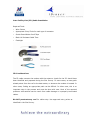
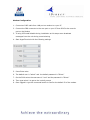
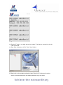
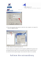
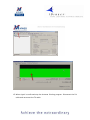
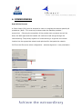
Installation &
Commissioning Guide
1. INTRODUCTION
PURPOSE
This manual provides the procedures required for an installation of the MWEB VSAT
terminal on customer premises.
Each installer should have received a copy of the MWEB Field Service Manual prior to
installation.
PRE – INSTALL
•
Site Survey Tools
•
Site selection
•
Inventory
•
Test equipment & Tools
STANDARD INSTALLATION
•
Dish Installation
•
Dish Pointing
•
IFL Installation
•
MODEM Installation & Configuration
COMMISIONING
•
System Commissioning
•
Peak & Pole Process
•
Compression Test
2. PRE – INSTALL
It must be stressed that the site survey is usually the first appearance of
MWEB Representatives at a customer’s site. The Representative is cautioned
to present a neat and professional demeanor at all times.
Site Survey Tools
In order to properly perform a site survey, the following tools are necessary in
addition to the Site Survey Form:
•
Compass
•
Inclinometer
•
Digital Camera
•
Tape Measure
Site Selection
Some things to consider when performing a site survey include:
•
Line-of-sight to the satellite (Azimuth / Elevation)
•
Type of mount to be used (Non-penetrating, pole etc.)
•
Roof type access
•
IFL route and length
•
IFL Point of Entry (POE)
•
Landlord approval
•
Permit requirements
•
Hours of access
•
Power requirements
•
Conduit requirements
•
Grounding requirements
•
Location of modem
•
Possible civil works required
Be on the look out for possible terrestrial interference especially on C-Band
Inventory
Perform Inventory check to verify all equipment has been received, and that it is of
the correct type.
KU-Band
•
Antenna
•
Antenna Mounting Mast
•
Feed Horn, the Ortho Mode Transducer (OMT) and the Transmit Reject Filter
(TRF).
•
Block Up Converter (BUC)—This is a cylinder-like device with ridges that
generates the transmit radio signal.
•
BUC Bracket—This is a metal unit that holds the BUC and is attached to the feed
arm of the antenna.
•
Low Noise Block (LNB) Receive radio signal
•
TX & RX IFL cable (RG6 – 30m. / RG11- 100m. /RG213 – 100m.)
•
Connectors F-type/N-Type (Equipment dependent)
•
IDU (Indoor unit)
•
IDU mounting brackets (Optional)
C-Band
•
Antenna
•
Antenna Mounting Mast
•
Feed Horn, Circular or Linear
•
Block Up Converter (BUC)—This is a cylinder-like device with ridges that
generates the transmit radio signal.
•
BUC Bracket—This is a metal unit that holds the BUC and is attached to the feed
arm of the antenna.
•
Low Noise Block (LNB) Receive radio signal
•
TX & RX IFL cable (RG6 – 30m. / RG11- 100m. /RG213 – 100m.)
•
Connectors F-type/N-Type (Equipment dependent)
•
IDU (Indoor unit)
•
IDU mounting brackets (Optional)
Test equipment and tools
Make sure that you have the necessary tools and test equipment:
•
Multi meter (Voltage, continuity etc.)
•
Satellite meter / Spectrum Analyzer (950 – 1750 MHz.)
•
Two way splitter with one DC Block / Pass
•
DC Power supply (Optional)
•
Cable Termination Tool Kit (Crimping tool for RG* connectors and Cable stripper)
•
Assorted adapters (F-type, BNC and N-type)
•
Water proofing tape (Scotch) (Self fusing)
•
GPS for Lat / Long
•
Assortment of Sockets, Spanners, Wrenches, Screw driver, Allen keys etc.
•
Laptop / PC
•
Standard LAN (Ethernet) X-Cable
•
Standard LAN (Ethernet) Straight Cable
3. STANDARD INSTALLATION
A standard installation will consist of the following:
•
Assembly and installation of mount on customer premises
•
Provision and installation of appropriate ballast
•
Assembly of 1.2M, 1.8M or 2.4M antenna, as required, on mount
•
Assembly and installation of outdoor electronics on antenna
•
Installation and termination of up to121.9M of IFL cable
•
Pointing, peaking and commissioning of the VSAT system
•
Verification of operation with the relevant NOC
•
Application testing as required by the customer
•
Site cleanup
•
Completion of the installation sheet
Dish Installation
Install dish as per manufacturer’s instructions
•
Ensure level surface, mount at 90 degrees
•
Ensure direct Line Of Sight to Satellite (No obstructions)
Dish Pointing
•
It is assumed that the dish has been properly mounted, facing the right direction,
with no obstruction and that the Installer has a known “beacon” frequency /
Symbol rate or a plot of the Satellites “signature”.
•
Tighten all bolts on Az./El. slightly to allow for movement without being loose
•
Adjust the dish to general azimuth direction – Taking magnetic declination into
account
•
Adjust the dish to the correct elevation angle – Taking the Dishes offset into
account
•
Rotate the Feedhorn to the correct polarisation (Looking towards Satellite, +
means Clockwise) – During cross polarisation checks fine tuning will be made in
coordination with the Hub operator
•
Connect Satellite meter with voltage selected to 13V
•
If using a Spectrum Analyser, make sure to set it up as in Fig. 1. (Insert correct
diagram)Make sure the 2-way splitter blocks the DC voltage from entering the
spectrum analyser
•
Tune the Satellite meter / Spectrum analyzer to the required “Beacon” frequency
/ Symbol rate of the Satellite
•
While observing the spectrum analyser, adjust the azimuth in 2 -3 degrees
increments. Span up to 15 degrees each side of the azimuth heading. If no
signals is found, raise (or lower) the elevation and repeat scan through azimuth
•
Once a frequency is found, confirm it is the correct satellite using the supplied
beacon frequency or signature
•
Make fine azimuth adjustments to peak the signal, tighten all azimuth bolts while
verifying that the signal strength stays the same.
•
Make fine elevation adjustments to further peak the signal, tighten all elevation
bolts while verifying that the signal strength stays the same
lnter-Facility Link (IFL) Cable Installation
Required Tools:
•
Wire Cutters
•
Appropriate Crimp Tools for each type of connector
•
Scotch Brand Water Proof Tape
•
Black UV Resistant Cable Tiers
•
Flashlight
IFL Considerations
The IFL cable connects the modem with the antenna. A path for the IFL should have
been identified and prepared during the Site Survey. In some cases, an easy path
already exists from the roof to the data center, or wherever the modem is located. In
other cases, finding an appropriate path can be difficult. In either case, this is an
important step in the process and must be done with care. Most of the reported
problems with satellite service result from cable damage or improperly terminated
cables.
DO NOT penetrate any roof for cable entry. Use approved entry points as
identified in the Site Survey.
Modem Configuration
1. Connect an RJ45 cable from LAN port on modem to a your PC
2. Connect the DB9 connector to the com port on your PC then RJ45 to the console
port on the Modem
3. If using XP firewall disable during installation as this stops some broadcast
messages from the unit during commissioning
4. Start HyperTerminal with the following settings
5. Press Enter twice
6. The default user is “admin” and the default password is “iDirect”
7. On the 3000 series the username is “root” and the password is “iDirect”
8. Then type telnet 0 to get to the Laninfo prompt
9. Once logged in type the command laninfo to confirm the default IP of the modem
10. Set the PC card to one digit above the modem IP and prove connectivity by the
PING command
11. Start iSite software go to file “New” then Modem
12. Right click on the modem and select Login Enter the IP of the unit from the
laninfo command and enter the default password log in as Admin
13. From the top menu select option file load from disc navigate to the option file
sent from MWEB Africa NOC
14. After loading the option file reset the unit.
The unit assumes the configuration and IP’s supplied by MWEB and the password will
be eutelsat Check the back of the unit and ensure the RX light is green Re-log into
the unit and check the signal strength Ensure that the TX cable is not connected.
15. When signal is confirmed stop the Antenna Pointing program. Disconnect the RX
cable and reconnect the TX cable.
4. COMMISIONING
Peak & Pole Process
A Carrier Wave (CW) must be activated in order to complete the antenna peak & poll
procedures. (Note – This must only be done under the Satellite providers supervision)
Following the completion of the provider test a pressure test will be
done, the NOC agent and the installer will continue to talk and go through the
commissioning. The primary objective of commissioning is to get the new remote
location into the appropriate network and optimized for that particular network.
CW From the iSite menu select configuration …antenna alignment...cross polarization
When confirmed to start, press the start button.
You will be instructed to tie down the antenna or to make some small adjustments if
needed to the antenna.
Once an acceptable isolation level is achieved the NOC will advice you to lock down
the antenna.
Compression Test
When confirmed to start press the start button and change the power setting as
directed from the
NOC.
Once the saturation level is achieved then the NOC will reset the max power of the
terminal.
Stop the compression test when directed by the NOC, de-power the modem then repower with TX
and TX cables connected.
Ensure the RX light goes green after restarting.
The NOC will then multicast to the modem the latest version of software after which
the modem will
reset.
After reset the modem the following lights should be green Status, RX, TX once the
unit locks to the
network the Net light will go green on the front of the unit and the rear. The unit is
then ready for use.
Please keep the option file safe in case of a need to reload and please use iSite
software to perform
local checks on the unit.
5. FAULT FINDING
•
Contact [email protected] or +27 21 596 8728
•
Ensure that all the necessary above mentioned steps have been
thoroughly completed and have all information retrieved handy.
•
Have a technical person on site that can assist the MWEB NOC with
troubleshooting if necessary