1
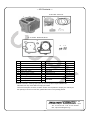
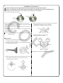
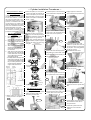
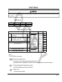
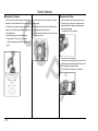
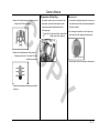
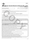
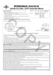
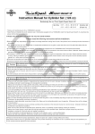
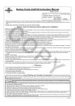
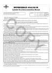
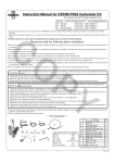
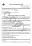
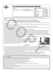
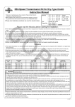
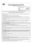
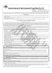
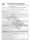
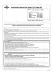
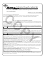
/ Instruction Manual for Cylinder Set
Exclusively for our
For exclusive use in motorcycles equipped with a CD90 engine with frame Nos from
CO
HA03-1100005 onwards
Item Nos:01−04−7001 (105cc)
・Thank you for purchasing one of our TAKEGAWA's products.
・This is a piston and cylinder set exclusively for R-Stage+D of our own manufacture. In using this set, please strictly observe the following.
◎ Please note that the descriptions in this manual like illustrations and photos may differ from the actual hardware.
Please read the following instructions before installation.
◎ We do not take any responsibility for any accident or damage whatsoever arising from the use of the products not in conformity with the instructions in
the manual.
◎ We shall be held free from any kind of warranty whatsoever of products other than this product if the glitch takes place on the other products than this
one after the installation and use of this product.
◎ This set is exclusively for R-Stage+D of our TAKEGAWA’s manufacture.
PY
◎ Please be informed that we shall be held harmless against any claim against us whatsoever arising out of use of the products in racing and the like.
Caution
The following show the envisioned possibility of injuries to human bodies or property damages as a result of disregarding the
following cautions.
・Since this kit is designed and developed for driving in closed races, do not use the kit for running on public roads.
・Work only when the engine and the muffler are cool. (Otherwise, you will burn yourself.)
・Prepare right tools for the work, and do the work in the proper and right way.(Otherwise, improper work could cause breakage of parts or injuries
to yourself.)
・As some products and frames have sharp-pointed or protruding portions, please work with greatest care. (Otherwise, you will suffer injuries.)
Warning
The following show the envisioned possibility of human death or serious injuries to human bodies as a result of disregarding the
following cautions.
・Those who are technically unskilled or inexperienced are required not to do the work. (Improper installation due to unskilled technique or lack of
knowledge could lead to parts breakage and consequently to accidents.) ・Always use new piston pin circlips, gaskets and packing. (Wear and damage to these parts are likely to cause parts breakage and accidents.)
・Before doing work, place the motorcycle on level ground to stablize the position of your motorcycle for safety's sake. (Otherwise, your motorcycle
could overturn and injure you while you are working.)
・If you find damaged parts when checking and performing maintenance of your motorcycle, do not use these parts any longer,
and replace them with new ones. The continued use of these damaged parts as they are could lead to accidents.)
・Always start the engine in a well-ventilated place, and do not start it in an airtight place. (Otherwise, you will suffer from carbon monoxide poisoning.)
・Before riding, always check every section for slack in parts like screws. If you find slack ones, screw them up securely to the specified torque.
(Or improper torque may cause parts to come off, leading to accidents.)
・When you notice something abnormal with your motorcycle while riding down a road, immediately stop riding and park your motorcyle in a safe place.
(Otherwise, the abnormaility could lead to accidents.)
・As gasoline is highly flammable, never place it close to fire. Make sure that nothing flammable is near the gasoline. (Otherwise, there will be a danger
of causing fires.)
・Check or perform maintenance of parts correctly according to the procedures in the instruction manual or a service manual. (Improper checking or
maintenance could lead to an accident.)
・Never use any other part than the specified parts. (Otherwise, there is a possibility of parts breakage, leading to accidents.)
・Always use a torque wrench to screw bolts and nuts tight and securely to the specified torque. (Otherwise, improper torque may result in the breakage or coming off of the bolts and nuts, leading to accidents.)
・As the accumulation of vaporized gasoline is at the high risk of explosion, work in a well-ventilated place.
・Always use high-octane gasoline. (Otherwise, troubles such as engine knocking may cause accidents.)
◎ Please be informed that the product specifications, design and prices are subject to change without prior notice.
◎ We shall be held free from any guarantee whatsoever of any trouble caused by the combined use of our products with parts not specified by us.
◎ This manual should be retained for future reference.
- A’1 -
Sep./08/’
09
∼ Kit Contents ∼
01-02-7001 : Piston kit
1
CO
2
3
4
5
01-13-7003V : Gasket kit, B set
8
6
No.
1
2
3
4
5
6
7
8
9
10
PY
7
9
10
Parts Name
Qty
Repair parts No.
Cylinder
1 12101-2HL-T00
Piston
1 13101-CDR-T00
Piston ring set(top, 2nd, oil) 1 01-15-014
Piston pin
1 00-01-0091 (with two circlips)
Piston pin circlip
2 00-01-0003
Cylinder head gasket
1 12251-GFL-T10
Cylinder gasket
1 00-01-0067
Rubber packing(black)
2 00-01-0066
Dowel pin, 8x12
2
00-01-0090
Dowel pin, 8x14
2
In packs of
1
1
1
1set
6
1
2
2
2
2
※Please note that in ordering repair parts, be sure to quote the Repair Part Item No. Otherwise, we may not be able to accept your orders.
There are some parts, however, for which we are not in a position to accept your order in just
the quantity to be used. In this case, please take them in the quantity packed.
Co.,Ltd.
3-5-16 Nishikiorihigashi Tondabayashi Osaka Japan
TEL : 81-721-25-1357 FAX : 81-721-24-5059
URL : http://www.takegawa.co.jp
- A’2 -
Sep./08/’
09
∼ Installation Procedures ∼
Caution: Always be sure to tighten parts to the specified torque using a torque wrench.
Notice: The unskilled or those without proper knowledge are requested not to do the installation work.
○The following show the products of our own make to which this kit cannot be installed.
◇ On the use of an old-type inner rotar CDI
CO
usable
unusable
one mounting tap
Tap for 88
Tap for 106
○Some products involve detachment and installation of an engine and sepration of a crank case, etc. Do the installation work infallibly, following
Honda’s genuine parts service manual.
・Measure the misalignment on the journal bearing of the crank shaft.
∴ Shaft direction:If larger than 0.10 mm, replace it.
Bearing direction: If larger than 0.05 mm, replace it.
○Referring to the service manual, detach the engine from the frame and disassemble it.
○ The crankcase requires processing. Process the crankcase referring
to the attached sheet.
PY
о Check every part.
Caution: Infallibly inspect every part and check consumable parts for
damage and wear.
What to check:
・Measure the deflection of the crank shaft.
∴ If larger than 0.10 mm, replace it.
・Measure the internal diameter at the small end of the con’rod.
∴ If larger than 13.03 mm, replace it.
・Measure the clearance at the big end of the con’rod in the axial direction.
∴ If larger than 0.6mm, replace it.
26mm
30mm
o Assemble the crankcase referring to the service manual.
・Measure the misalignment at two points at the big end of the con’rod at
right angles to the shaft as shown in the figure on the right.
∴ If larger than 0.05mm, replace it.
Y
X
-1-
Sep./08/’
09
∼ Cylinder Installation Procedures ∼
Some precautions to take in
installing cylinder:
In some cases, due to right and left
crankcases being out of alignment
and for other reasons, in installing
the cyliner, the sleeve hole on the
crankcase’s mating surface, circled
portions, the shaded area of the
cylinder sleeve, and inside of the
case may interfere with one another.
Since such interference will lead to
sleeve deformation and cause
engine troubles, do not fail to check
the existence of interference and
prevent the interference.
○ Attach the piston pin circlip so the
ring end gap does not meet with the
notch on the piston pin hole, and it
should be either on the top or at the
bottom of the piston as illustrated in
the fig. 1 below.
CO
Tips on how to prevent
interference
1.Cover the crankcase securely with a waste cloth so the
shavings will not fall down into it.
2.Rasp the convex portions on the
mating surfaces of the crankcase
till the mating surfaces become level
with each other.
3.After rasping the convex portion,
remove the waste cloth with care
not to let the shavings go inside the crankcase.
4.After removing the waste cloth,
fill the hole on the crankcase with
a clean waste cloth so the parts
may not fall into the crankcase while installing the Kit.
※ It is likely that the shavings have
fallen into the crankcase. So, after
you have finished installing the Kit,
let your motorcycle idle for a few
minutes, and then replace the
engine oil with the new one.
Right side
crankcase
Left side
crankcase
○ Air-blow the piston rings and the piston pin, and check for jamming of
any foreign material by these parts.
○ Apply engine oil to grooves for
piston rings, and, with reference to
the figure below, fix piston rings and
arrange the location of piston ring
end gaps.
○Plug the sleeve hole and the cam chain hole on the crankcase with a
clean cloth, and fix a piston pin circlip.
NEW
Second ring
Expander
PY
○Remove the cloth used to plug holes.
○ Degrease the cylinder base of the
crankcase, and fix 8x12 dowel pins
onto the dowel pin holes.
○ Place the cam chain guide roller
on the cam chains.
Side rails
60° 60°
○ Fix a cylinder gasket of the kit into
the cylinder base of the crankcase.
NEW
IN
After ectiflcation
Top ring
Second ring
Sleeve
Interferring section
Cylinder
○ Loosely tighten the cam chain guide roller and the cylinder side
bolt.
Side rails
Piston
Expander
Pay attention to the cross
section as well!!
○ Attach a piston pin circlip to one
of two pin holes on the piston.
○ Compressing the piston rings,
install the cylinder with care not
to move the piston-ring end gaps
out of place. Their end gaps will
not be out of place.
CAUTION: Be careful not to
damage the piston rings.
120°
120°
Gasket
○ Apply engine oil to the entire
inner surface of the cylinder bore.
○Insert the cylinder into the stud bolts.
End gaps
Top ring
120°
○ Install the piston to the connecting
rod so the IN mark on the piston faces
the intake side.
○ Apply molybdenum solution to the
piston pin and the holes on the
connecting rod small end.
○ Fix a new rubber packing (black) of
the kit onto the oil-return hole on the
cylinder base of the crank case.
NEW
MO-OIL
○Loosely tighten an original hex bolt
which holds the crank case on the cylinder side.
NEW
-2-
○ Install the cylinder head with
reference to the instruction manual.
Sep./08/’
09
CO
Owner’s Manual
WARNING
Since this cylinder manual is prepared for those who have acquired basic skills and knowledge in tuning, those who are technically unskilled or inexperienced are required
not to do the work.
Specification List
Item No.
01-04-7001
Bore stroke
52 x 19.5
Displacement
105.1 cm 3
Compression ratio
12.0
PY
Specification List for Cylinder & Piston
Item
Cylinder Distortion
Internal diameter
φ52
Piston External diamter(4 mm from the hem of a skirt) φ52
Internal diameter of a pin hole
External diameter of a piston pin
Piston ring end gap size
Top
2nd
Oil
Clearance between cylinder and piston
Clearance between piston and pin
○Torque unit
1 kgf・m = 9.80665 N・m (=newton meter)
MO-OIL
○This mark shows molybdenum solution.
Stock
52.015∼52.070 mm
51.980∼52.000 mm
13.002∼13.008 mm
12.994∼13.000 mm
0.15∼0.38 mm
0.20∼0.45 mm
0.20∼0.70 mm
0.002∼0.014 mm
Service limit
0.05 mm
52.10 mm
51.96 mm
13.03 mm
12.98 mm
0.50 mm
0.50 mm
0.90 mm
0.12 mm
0.05 mm
Remarks
Replace
Replace
Replace
Replace
Replace
Replace
Replace
Replace
Replace
Replace
This solution is a mixture of molybdenum grease and engine oil (in the ratio of 1:1).
∴Apply molybdenum solution or assembly paste to the portions where it is indicated that molybdenum solution needs to be applied.
NEW
○This mark shows those parts to be replaced with every overhaul.
Do not fail to replace these parts every time they are overhauled.
OIL
○ Engine oil → mark
∴Apply engine oil where so indicated.
- C ’1 -
CO
Owner’s Manual
● Inspection of Cylinder
・Check the inside of cylinder for wear and damage.
● Inspection of Piston
・Check the top surface of the cylinder for scratches
・Measure the internal diameters of the cylinder bore
and damages.
at 6 positions; at the piston pin angle and at the right
angle to it (X-Y) each at upper, middle and lower parts
・Check the cylinder top surface for distortion with a
straight edge and thickness gauge.
of the cylinder bore.
Treat the largest value as its internal diameter.
∴Service limit:If the distortion is more than 0.05 mm,
replace the cylinder.
・Clear the piston of the remaining carbon residue.
・Fit a piston ring into the piston, and measure the clearance between the piston ring and ring groove with a thickness gauge.
∴If larger than 0.17mm, replace it.
∴ If larger than 52.10mm at φ 52, replace it.
Calculate the clearance between a cylinder and a
piston.
IN
上
中
下
-C’2-
Y
EX
X
PY
・Check the piston for damages.
・Measure the external diameter of the piston at the
specified place at the bottom edge of the piston skirt
at the right angle to the piston holes.
∴ If smaller than 51.96mm at φ 52, replace it.
CO
Owner’s Manual
● Inspection of Piston Ring
●Supplement:
・Measure the internal diameter of the piston pin hole.
・Press down a piston ring into the piston with the ・If you intend to change the piston with a new one, you
∴If larger than 13.03mm, replace it.
piston head, and measure the clearance of the
can order the one from us by the number stamped on
ring-end gap at the horizontal position with a
thickness gauge.
the top of the piston.
∴Top and 2nd : If larger than 0.5mm, replace them.
Oil
: If larger than 0.9mm, replace it.
・Measure the external diameter of the piston pin.
∴Piston pin service limit : If it is below 12.98 mm, replace the piston pin.
・Calculate the clearance between the piston and the piston pin.
PY
・After removing the carbon stuck on the piston top,
take a note of the No. stamped on the piston top.
Example:13101-CDR-T00
・Order the piston by the No. stamped on the piston top.
- C ’3 -