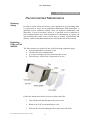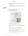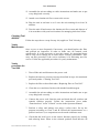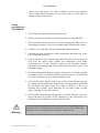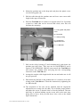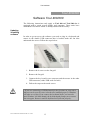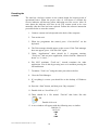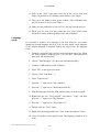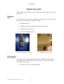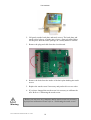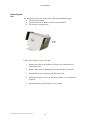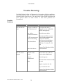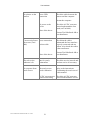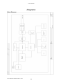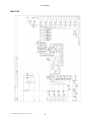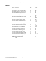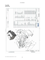
1
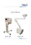
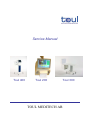
Service Manual Toul 400 Toul 200 TOUL MEDITECH AB Toul 300 Toul ® is registered by TOUL Meditech AB Toul 400, Toul 300 and Toul 200 bears the marking and complies with the provisions of the Medical Device Directive 93/42 EEC. Toul Meditech AB takes no responsibility for use of the product other than for those uses specified herein and disclaims any liability resulting from other uses. Observe all warnings and precautions. This manual covers software version 2.0 for Toul 400 and Toul 200. Manual, revision 1.6 January 2007 Toul Meditech AB Copyright Toul Meditech AB 2006. All rights reserved. Unauthorized use, copying, or distribution of this manual is prohibited without the written permission from Toul Meditech AB. Content Toul 400/300/200....................................................................................................................... 5 Recommended Maintenance ............................................................................................................ 5 Ensuring Safety ............................................................................................................................................. 5 Replacing Filter on Toul 400/200.................................................................................................................. 5 Replacing Filter on Toul 300......................................................................................................................... 6 Contaminated Unit/Cleaning ......................................................................................................................... 7 Cleaning Toul 300 ......................................................................................................................................... 7 Cleaning Toul 400/200 .................................................................................................................................. 8 Yearly Maintenance....................................................................................................................................... 8 Yearly procedure for Toul 300 ...................................................................................................................... 8 Yearly procedure for Toul 400/200 ............................................................................................................... 9 Toul 200 ................................................................................................................................... 10 Installation instruction for Toul 200 ............................................................................................. 10 Ondal Space Pendant................................................................................................................................... 10 Electrical installation ................................................................................................................................... 10 Mounting Toul 200...................................................................................................................................... 10 Toul 400/200 ............................................................................................................................ 13 Software Toul 400/200 .................................................................................................................... 13 Updating /Installing software ...................................................................................................................... 13 Resetting the counter ................................................................................................................................... 14 Calibrating the touch screen ........................................................................................................................ 15 Language setup............................................................................................................................................ 16 Replacing parts................................................................................................................................ 17 Replacing fuses............................................................................................................................................ 17 Removing the touch screen.......................................................................................................................... 17 Removing the fan ........................................................................................................................................ 19 Trouble Shooting............................................................................................................................. 20 Possible Problems........................................................................................................................................ 20 Diagrams.......................................................................................................................................... 22 Block Diagram............................................................................................................................................. 22 Main PCB .................................................................................................................................................... 23 Parts list ....................................................................................................................................................... 24 Toul 200 illustration .................................................................................................................................... 25 Toul 400 illustration .................................................................................................................................... 26 Manufacturer........................................................................................................................... 27 How to get in contact with Toul Meditech AB............................................................................................ 27 Service Manual Toul 400 300 200 ver 1.6.doc 3 Service Manual Toul 400 300 200 ver 1.6.doc 4 Toul 400/300/200 Toul 400/300/200 Recommended Maintenance Ensuring Safety In order to ensure safety and to keep your equipment in good working order it is necessary to carry out recommended maintenance and inspections. A qualified service technician should carry out technical maintenance and inspection. If you do not have access to a qualified service technician in your hospital contact your local distributor for information on whom you can consult for the yearly service of your unit, or contact Toul Meditech AB directly. Address and phone numbers are listed at the end of this manual. Replacing Filter on Toul 400/200 The filter needs to be replaced if any of the following conditions apply: • Yearly Maintenance procedure is due • The filter has been contaminated • A service warning has been presented on the screen • The efficiency of the filter is suspected to be low Follow the instructions below on how to replace the filter. 1. Turn off the unit and disconnect the power cord. 2. Remove the LAF screen and dispose of it. 3. Unscrew the 4 bolts holding the filter and remove the filter. Service Manual Toul 400 300 200 ver 1.6.doc 5 Toul 400/300/200 4. Mount a new filter with the rubber gasket facing towards the fan box. Dispose the old filter according to your local waste management regulations. 5. The operational counter has to be reset after replacing the filter. Refer to “Resetting the counter” in the Software instructions section. Replacing Filter on Toul 300 The filter needs to be replaced if any of the following conditions apply: • Yearly Maintenance procedure is due • The filter has been contaminated • The efficiency of the filter is suspected to be low 1. Turn off the unit and disconnect the power cord. 2. Remove the LAF (laminar air flow screen) and dispose of it. 3. Loosen the metal grid and the inner air pressure screen for dispersion of the airflow. 4. Replace the air pressure screen. Put back the metal grid. 5. Unscrew the 4 bolts holding the filter and remove the filter. 6. Replace the filter for a new one and make sure to put the new filter with the rubber gasket facing towards the fan box. 7. Dispose the old filter and the air pressure screen according to your local waste management regulations. Service Manual Toul 400 300 200 ver 1.6.doc 6 Toul 400/300/200 Contaminated Unit/Cleaning If the unit has been contaminated during a procedure, or if liquid has been spilled inside the unit, you must take special precautions. Always wear rubber gloves when such cleaning should be performed. The Operator’s manual contains information on how the screen should be decontaminated. For internal cleaning follow the applicable cleaning instructions below in accordance with your model: Cleaning Toul 300 1. Turn off the unit disconnect the power cord. 2. Remove the single-use laminar air flow screen and dispose of it in accordance with your local routines for managing infectious refuse. 3. Unscrew the 4 bolts on the filter holders and remove the filter according to previous instructions. 4. Loosen the metal grid and the inner air pressure screen for dispersion of the airflow. 5. Clean the metal grid with a cleaning solution of low level disinfectant, such as isopropyl alcohol or similar. Leave to dry. 6. Replace the inner air pressure screen with a new. Put back the metal grid. 7. Moisten a soft cloth with a cleaning solution of low level disinfectant, such as isopropyl alcohol or similar, and wipe all easily accessible inner and outer surfaces gently. Clean the inner fan box with alcohol based detergent. The frame where the filter gasket is fitted must be thoroughly cleaned with alcohol. 8. Remove any debris or dirt. Use a vacuum cleaner on the power box. 9. If liquids have entered the unit, leave the unit to dry for at least 24 hours. It should be disassembled and turned off, and be placed in room temperature. 10. Inspect all connectors, inlets and openings and make sure that no stains, soil or dust is present. 11. Inspect the filter thoroughly before you put it back. If the filter has been soiled/spilled on it should be replaced with a new one. Service Manual Toul 400 300 200 ver 1.6.doc 7 Toul 400/300/200 12. Assemble the unit according to earlier instructions and make sure to put every thing back correctly. 13. Attach a new laminar air flow screen to the screen. 14. Plug the unit in and turn it on. Leave the unit running for at least 30 minutes. 15. Turn the unit off and remove the laminar air flow screen and dispose of it in accordance with your local routines for managing infectious refuse. Cleaning Toul 400/200 Follow the steps above except for step 4-6 (applies to Toul 300 only). Yearly Maintenance Once a year, or more frequently if necessary, you should replace the filter and perform an inspection in order to make sure all controls work satisfactorily. It is also necessary to reset the counter for operational hours and to carry out a leakage test in order ensure accurate performance. Also carry out this procedure if the service indicator is lit indicating need for service. Follow the applicable procedure for yearly maintenance. Yearly procedure for Toul 300 1. Turn off the unit and disconnect the power cord. 2. Replace the inner air pressure screen as described in steps 4-6 mentioned previously under “Cleaning Toul 300”. 3. Replace the filter as described under “Replacing filter on Toul 300”. 4. Clean the cover and inner fan box with alcohol based detergent. 5. Assemble the unit according to earlier instructions and make sure to put every thing back correctly. 6. Connect the power cord. Start the unit and check that all switches and controls function properly. Follow the instructions given under “Functional test” in the “General” section in the Operators manual. 7. Perform a safety and leakage test using a safety tester. Set up the program according to Class I and B. Record the measurements on a protocol and save it, so comparisons can be made with future tests. 8. Check that the lock levers on the castors function properly by locking and releasing them. When in the released position check that the all Service Manual Toul 400 300 200 ver 1.6.doc 8 Toul 400/300/200 castors can rotate freely. If a castor is defective it has to be replaced. Also visually check that there are no cracks, dents or other signs of damage on any of the castors. Yearly procedure for Toul 400/200 1. Turn off the unit and disconnect the power cord. 2. Replace the filter as described in “Replacing filter on Toul 400/200). 3. The operational counter has to be reset after replacing the filter. Refer to “Resetting the counter” in the Service instructions Toul 400/200 section. 4. Clean the cover and inner fan box with alcohol based detergent. 5. Assemble the unit according to earlier instructions and make sure to put every thing back correctly. 6. Connect the power cord. Start the unit and check that all controls can be used from the touch screen. Follow the instructions given under “Functional test” in the “General” section in the Operators manual. Check that the warning lamp on top of the unit turns off as soon as the fan starts running. 7. Perform a safety and leakage test using a safety tester. Set up the program according to Class I and B. Record the measurements on a protocol and save it, so comparisons can be made with future tests. 8. On Toul 400, check that the lock levers on the castors function properly by locking and releasing them. When in the released position check that the all castors can rotate freely. If a castor is defective it has to be replaced. Also visually check that there are no cracks, dents or other signs of damage on any of the castors. 9. On Toul 200, check that the pendant arm is correctly balanced, can move freely and stays in position. If the suspension of the arm needs to be adjusted refer to installation instruction of Toul 200. Warning - Be sure to put back all parts in the correct order after finishing service and inspection. The filter may not be fitted incorrectly. Check especially that there are no remaining items, outside or inside the unit. Service Manual Toul 400 300 200 ver 1.6.doc 9 Toul 200 Toul 200 Installation instruction for Toul 200 The following installation instruction regarding mounting the unit and pendant arm into the ceiling only apply to Toul 200. Ondal Space Pendant The pendant that supports Toul 200 is manufactured by Ondal Space. Upon delivery Toul 200 is accompanied with a separate instruction for the Ondal Space pendant. Refer to this instruction before you start mounting the pendant and select the appropriate mounting option that corresponds to the requirements and the construction of the ceiling. Electrical installation Electrical installation is required and the ceiling space where the pendant arm shall be mounted must be prepared with electrical wiring and a socket. The electrical installation shall be connected to a single fuse and a main power switch needs to be mounted on the wall. All electrical installation steps must be carried out by a certified electrician. Consult with the maintenance department at the Hospital, since they most likely have qualified staff or can give advice who to contact. Warning - When mounting the Ondal Space pendant it is necessary to be at least two persons. The device is heavy and it requires extra hands to hold some items while mounting the pendant. Mounting Toul 200 For mounting the Toul 200 and the pendant arm follow the steps below and see the illustration on next page. 1. Measure all parts and adjust the lengths of the fixating items. It might be necessary with some slight adjustments. 2. Start by mounting the fixing plate (A) into the ceiling. Connect the earth wire to the earth pin on the fixing plate (to be connected by a certified electrician). 3. Mount the drop tube (B) on the fixing plate. The drop tube (B) can be sawed into the correct length. Service Manual Toul 400 300 200 ver 1.6.doc 10 Toul 200 4. Mount the pendant arm on the drop tube and place the plastic cover over the fixing plate (A). 5. Pull the cable through the pendant arm and leave some extra cable length in the upper connection. 6. Place the Toul 200 unit on a table or a support stand. Use if possible a stand or a table that can be lowered and raised, since this will facilitate the mounting. A = Fixing plate and plastic cover B = Drop tube C = Safety locking D = Suspension adjustment screw E = 4 x 8M bolts 7. Pull out the safety locking (C) and simultaneously push down the pendant arm with force. This step can be DANGEROUS and it requires TWO PERSONS. Shift the arm towards the Toul 200 unit and connect the pendant cable and plug into the corresponding connector on the Toul 200 unit. 8. Arrange the surplus cable length inside the arm and make sure it will not get squeezed. 9. Push down the final bit on the pendant arm so it connects in its tube seating on the Toul 200 unit. Fixate the connection by tightening the 4 x 8M bolts (E). 10. The suspension of the arm can be adjusted with the suspension adjustment screw using a hex-key (D). Try to find the proper balance and adjust the screw so that the arm is correctly balanced. The arm shall stay in position holding up the screen and at the same time being able to move freely up and down. Also refer to the Ondal Space instruction. Service Manual Toul 400 300 200 ver 1.6.doc 11 Toul 200 11. Start the Toul 200 unit. Refer to the Toul 200 Operator’s manual. - Adjusting the suspension might be necessary to repeat once in a while. The suspension shall be checked on the yearly procedure. Note Service Manual Toul 400 300 200 ver 1.6.doc 12 Toul 400/200 Toul 400/200 Software Toul 400/200 The following instructions only apply to Toul 400 and Toul 200 that is equipped with a touch screen display and computer. These units have embedded XP software which is already installed at the factory. Updating /Installing software In order to get access to the software you need to plug in a keyboard and mouse in the double USB connector that is located under the fan inlet underneath the screen. Follow the steps below: 1. Remove the 6 screws on the fan grid. 2. Remove the fan grid. 3. Connect the key board in one connector and the mouse in the other USB connector (either USB work for both) 4. Follow the steps on the touch screen. Note - If you are connecting a USB keyboard for the first time on your unit it may not work correctly since it needs to be installed properly. Windows will take care of this if you connect the keyboard before you start the unit. Windows will then identify the keyboard and prompt you to restart the unit again. Restart it and the keyboard will function properly. Service Manual Toul 400 300 200 ver 1.6.doc 13 Toul 400/200 Resetting the counter The unit has a built-in counter on the control board for keeping track of operational hours. When the preset value of 1950 hours is reached the Service indicator will become yellow indicating need for service. After 50 more hours the indicator will alert in red. The counter needs to be reset manually after the filter has been replaced. Follow the software instruction procedure below to reset the counter: 1. Connect a mouse and a keyboard to the back of the computer. 2. Turn on the unit. 3. When the programme has started, press “Ctrl+Alt+Del” on the keyboard. 4. The Task manager should appear on the screen. If the Task manager does not appear, press “Ctrl+Alt+Del” again. 5. Under “Applications” there should be 2 programs running, “Toul1.exe” and one more application, which could be “Shortcut to down” or “C:/cmd…” 6. DO NOT terminate “Toul1.exe”, instead terminate the other application. You do this by pressing once on it and then pressing the end task button. 7. Terminate “Toul1.exe” using the same procedure as before. 8. Close the Task Manager. 9. If everything is correct you should be at the desktop of Windows XP. 10. Press the “Start” button, and then press “My computer”. 11. Double click on “Local Disc (C:)” 12. There should be a file named “Toul.ini” that looks like this Double click on it. 13. A new window will appear with the following text, or similar: 2006-06-21 14:51:06 1000 28 1000 Service Manual Toul 400 300 200 ver 1.6.doc 14 Toul 400/200 1200 1000 14. The bold text that is displayed is the only text you will need to change (The numbers will be different from what is displayed here). 15. Change the text to 0 so it looks like this: 2006-06-21 14:51:06 0 0 0 1200 1000 16. Press “File” and then “Save”. 17. Restart the computer and the counter should reset to zero. If for some reason it is not, redo the whole procedure. Calibrating the touch screen If there is no communication with the touch screen or if it is misaligned you need to calibrate the touch screen. It is also necessary to calibrate the screen if the computer or the touch screen has been removed and/or replaced. When calibrating the touch screen make sure it is connected to the power supply. Follow the procedure to calibrate the touch screen: 1. Connect a keyboard and a mouse to the unit then start it up. 2. When the Toul program is running, press ”Ctrl+Alt+Del”. (Hold down Ctrl then press Alt and then Del) 3. Choose ”Task Manager” if it does not start automatically. 4. Press ”File” in the upper left corner. 5. Choose ”New Task (Run…)” 6. Write ”Explorer.exe” 7. Press the ”+” sign next to ”My computer” 8. Press the ”+” sign next to ”Local Disk (C:)” 9. Press the ”+” sign next to the ”Program Files” folder. 10. Press once on the ”EloTouchSystems” folder, not at the + sign! 11. Find the ”EloVa.exe” icon in the right window and double click it. Service Manual Toul 400 300 200 ver 1.6.doc 15 Toul 400/200 12. Point at the ”Aim” signs that comes up at the screen with your finger, Then check to see that the pointer follows your finger. 13. Then press the button with a green symbol. (The calibration may need to be done twice or even 3 times.) 14. Make sure the calibration is correct. If it’s not just redo the process. 15. When you are done you can restart the unit. Your touch screen should be working without problems after the calibration. Language setup It is possible to install a new language on the unit. However, you cannot change an existing language this way. You can only install a new language if the original language is English. Follow the steps below for language setup. 1. Connect a keyboard and a mouse to the unit then start it up. When the Toul program is running, press ”Ctrl+Alt+Del”. (Hold down Ctrl then press Alt and then Del) 2. Choose ”Task Manager” (if it does not start automatically). 3. Connect a USB-memory in the USB port. 4. Press ”File” in the upper left corner. 5. Choose ”New Task (Run…)” 6. Write ”Explorer.exe” 7. Press the ”+” sign next to ”My computer” 8. Press the ”+” sign next to ”Removable Disk (E:)” 9. Find the language file in the USB-memory that you wish to install. 10. Right-click the file ”Toul_lang.dll” and choose ”Copy” and then press the ”+” sign next to ”My computer” 11. Press the ”+” sign next to ”Local Disk (C:)” 12. Double click the ”Toul” folder. 13. Right-click the background in the ”Toul” folder and choose ”Paste” 14. Close all windows and restart the unit. The language should now be setup. Service Manual Toul 400 300 200 ver 1.6.doc 16 Toul 400/200 Replacing parts This section describes how to remove specific parts of the unit in a safe and proper way. Replacing fuses The 2 fuses are placed in the compartment just above the power switch. If the fuses need to be replaced follow these steps: 1. Disconnect power 2. Open the lid of the compartment by unlocking the tab. 3. Replace the fuses with 5 A. 4. Close the compartment lid. Fuse compartment Toul 400 Fuse compartment Toul 200 Removing the touch screen The touch screen is mounted on the back plate with bolts from the inside. The back plate itself is mounted on the screen box. To remove the touch screen follow these steps: 1. Loosen the 12 screws on the back plate. Service Manual Toul 400 300 200 ver 1.6.doc 17 Toul 400/200 2. Lift gently out the back plate and touch screen. The back plate and touch screen is heavy so make sure to have a firm grip when lifting out the parts. Rest the whole package on a steady bench or similar. 3. Remove the plug and cable from the circuit board. 4. Remove the bolts from the inside of the back plate holding the touch screen. 5. Replace the touch screen if necessary and put back in reverse order. 6. If you have changed the touch screen it is necessary to calibrate the unit. Refer to “Calibrating the touch screen. - Before you can use a new computer and/or touch screen it is necessary to perform a calibration. Please refer to “Calibrating the touch screen” Warning Service Manual Toul 400 300 200 ver 1.6.doc 18 Toul 400/200 Removing the fan The fan may need service if any of the following conditions apply. • The fan will not start • The fan seems to be stuck or doesn’t run smoothly • The fan has a strange noise Follow these steps to remove the fan: 1. Remove the filter in accordance with previous instructions on “Replacing filter” 2. Remove the screws holding the fan on the stainless steel plate. 3. Disconnect the fan connector and lift out the fan. 4. Perform necessary service on the fan or replace it if it can not be repaired. 5. Mount back the fan and filter in reverse order. Service Manual Toul 400 300 200 ver 1.6.doc 19 Toul 400/200 Trouble Shooting Toul 400/200 has built-in self-diagnostics for detection of faulty conditions. Detected problems, need of service or an internal equipment failure are presented on the touch screen. The table below lists possible problems and gives general advice on what actions to take when problems are encountered. Possible Problems Problem The unit doesn’t start Possible Cause Remedy The power cable has been disconnected Check that the cable is plugged in at the wall outlet and the unit properly Rear cables disconnected/broken Check the rear cables Check the AC/DC converter AC/DC converter not located underneath the foot connected/working stand (on Toul 400). The fuses are located above the power switch. Replace A fuse has blown with fuse: 5 A slow, 5 x 20 mm The fan doesn’t operate None of the above Contact Toul Meditech AB or your distributor The unit needs service Check if the unit is due for service (after 2000 hours) Power is disconnected Check the power. Check the fan connector inside the unit. Other Repair or replace the fan. Try to restart the unit Contact Toul Meditech AB or your distributor Service Manual Toul 400 300 200 ver 1.6.doc 20 Toul 400/200 No picture on the camera Loose USB connection Check the cable between the camera and the computer Restart the computer No power to the screen Check the AC/DC converter located underneath the foot stand (on Toul 400). None of the above Contact Toul Meditech AB or your distributor Can not raise/lower Loose connection the screen (Toul 400) Broken cable Check that the cables underneath the foot stand are properly connected and not broken. Also check the cables at the transformer. None of the above Contact Toul Meditech AB or your distributor The red service indicator is lit Due for yearly maintenance Check the service interval and perform service if necessary No response from touch screen The touch screen needs calibration Refer to the instructions “Calibrating the touch screen” in this manual. AC/DC converter not Check the AC/DC converter connected/working located underneath the screen Service Manual Toul 400 300 200 ver 1.6.doc 21 Toul 400/200 Diagrams Block Diagram Service Manual Toul 400 300 200 ver 1.6.doc 22 Toul 400/200 Main PCB Service Manual Toul 400 300 200 ver 1.6.doc 23 Toul 400/200 Parts list Part No Description 3701-0003 Relay 12V 8A 1vxl G6RN-1 12VDC 3701-0009 Relay 12V 8A 2vxl G2RL-2-12 Omr 4303-0002 Pin list 1x2p straight gold 5-0826 4400-3204 Pin connector 4p floppy 0-641737-1 4406-1625 D-SUB 25p connector bent PCB bo 4810-0302 MKDSN-1,5/2-5,08 (282837-3 1m 6001-1004 1kohm 1% 0,6W resistor met.film 6001-1007 1Mohm 1% 0,6W resistor met.film Qty. 4 8 1 6 1 1 3 1 2 6001-2203 220ohm 1% 0,6W resistor met.film 6 6001-6803 680ohm 1% 0,6W resistor met.film 6001-8203 820ohm 1% 0,6W resistor met.film 6401-1005 10kohm 67W / 3296W trimpot 6501-0135 10nF 10% 50V X7R 5,08mm ker 8 2 1 6 6503-0120 100nF 10% 100V 7,5mm poly met, 6513-0010 220pF 25V DSS706-431D221M25-50 6519-0016 1000uF 16V 20% 5mm ellyt stand 1 7 3 7002-0051 BZX55C5V1 5,1V 0,5W zener 7010-0003 1N4007 diode 1000V 1A 7024-0005 E153 constant current diode Ip 12–1 7309-0245 74ALS245 Octal bus transceiver 7313-0106 40106 hex schmitt-trigger inve 7315-0014 OPA337PA Rail-to-rail op med f 7316-0043 7805 5V 1,5A TO-220 regulator 7317-0021 ULN2803A transistor array 8xNPN 7501-0009 LED green 3mm HLMP-1501 5,5 7501-0011 LED red 3mm HLMP-1301 5,5m EM Elektronik mekanik logo MKKDS 1.5 48-5.08 NP-HOLE020 2.0 mm unplated hole UH1 5 1 5 1 1 1 1 1 9 6 1 1 Service Manual Toul 400 300 200 ver 1.6.doc 24 Comps. UH2-5 K1-8 K9 J2-7 X2 X6 X3-5 R21 R19 R22 R1 R6-10 R11-18 R2-3 R20 C1-3 C5-6 C9 C14 LC1-7 C4 C7-8 Z2-6 V9 D6-10 D2 D3 A2 A1 D1 V11-19 V1-6 U1 X1 2 Toul 400/200 Toul 200 illustration Service Manual Toul 400 300 200 ver 1.6.doc 25 Toul 400/200 Toul 400 illustration Service Manual Toul 400 300 200 ver 1.6.doc 26 Manufacturer How to get in contact with Toul Meditech AB Toul Meditech AB Jonasborgsvägen 26 723 41 Västerås Sweden Phone: int + 46 21 13 50 00 Fax: int + 46 21 13 86 45 Internet: www.toul.se E-mail: [email protected] Your distributor: Service Manual Toul 400 300 200 ver 1.6.doc 27 Toul Meditech AB Jonasborgsvägen 26 723 41 Västerås Sweden