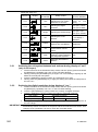
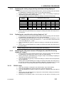
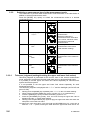
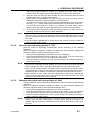
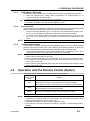
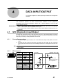
1
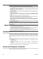
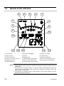
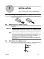
User’s Manual No. 99MAH016B3 SERIES No. 543 ID-H0530/0560 Digimatic Indicator User’s Manual Read this User’s Manual thoroughly before operating the instrument. After reading, retain it close at hand for future reference. FOREWORD In order to use this Digimatic Indicator properly, read this manual thoroughly before operating the instrument. After reading this manual, store it in a safe place for future reference. Mitutoyo assumes no liability to any party for any loss or damage, direct or indirect, caused by use of this instrument not conforming to this manual. Information in this document is subject to change without notice. 2013 Mitutoyo Corporation. All rights reserved. PRECAITIONS Precautions against the Power Supply WARNING Wrong handling that neglects the following precautions could result in serious injury or death. This instrument is externally powered from the AC power supply via the AC adapter. Be sure to use the Mitutoyo specified AC adapter (standard accessory: No.06AEG180). If this instrument is used near the machines that require a high voltage, high frequency, or large current, do not share the power line of the AC adapter with those machines. Use the AC power supply that absolutely conforms to the voltage and frequency indicated on the AC adapter. If the AC adapter is used under the condition exceeding the permissible voltage range, it could cause an explosion or ignition. If this instrument is not used for an extended period of time, make sure that the AC adapter is unplugged from the power supply to prevent fire, etc. Precaution in Discarding This Instrument WARNING Wrong handling that neglects the following precautions could result in serious injury or death. This instrument uses liquid crystal. If discarding this instrument, observe the ordinance and regulation by each local government. The liquid crystal includes an irritating substance. Should any liquid content be accidentally applied to your eyes or skin, wash them with clean flowing water. If you swallow the liquid content, immediately rinse your mouth, and after drinking a large amount of water, vomit it, and then consult a doctor. Precaution for Use The following acts or circumstances will cause a failure or a malfunction in this instrument. Care should be exercised. IMPORTANT Do not apply a sudden impact such as a drop or excessive force to this instrument. Do not disassemble or retrofit the instrument. Do not operate keys with a sharp tip (such as the tip of a screwdriver or ball point pen). Avoid using and storing this instrument at sites where it is subject to direct sunlight and excessively hot or cold environments. The use of this instrument at a site with tenuous air or high pressure could cause a failure due to deterioration in material. No. 99MAH016B i Avoid storing the instrument at sites surrounded with high humidity and dust, and avoid using it at sites where it is subject to direct splashes of water and oil. If a high-voltage device such as an electric pen is used, electronic parts may be damaged. Also, using the instrument at a site where large electric noises are generating could cause a malfunction. Use this instrument at a site with minimum vibration while securely fixing it on the comparator stand. Do not use this instrument in such a way that a perpendicular load or a twisting force is applied to the spindle. To clean the instrument, use a dry soft cloth or cotton swab, or one soaked in diluted neutral detergent. Use of organic solvents (such as thinner or benzene) may result in failure. The dirt in the spindle and cylinder will cause a malfunction. Wipe off dirt on the spindle with a cloth damped with alcohol, and then lightly wipe the spindle with a cloth damped with a small amount of low-viscosity oil. Clean the inside of the cylinder periodically. After removing the cylinder by rotating it, brush off the dust and dirt on and around the piston and in the cylinder using a brush or a blower brush. Take sufficient damage-preventive measures (safety measures) for an accidental failure of this instrument. The following precautions are important to obtain correct measurement results. Care should be taken. IMPORTANT Perform sufficient thermal stabilization of this instrument and an object to be measured before starting measurement. Use this instrument at a site which is subject to as little thermal fluctuation as possible. To perform stabilized measurement, allows approximately 20 minutes after turning on the power. The base line could be drifted approximately 0.5μm. Do not use this instrument with either stroke end specified as the reference point. Note that, if this instrument is used in other than the specified conditions, the functions and performance will not be guaranteed. WARRANTY This Digimatic indicator has been manufactured under Mitutoyo’s rigorous quality control system. In the event that this instrument should fail within one year from the original date of purchase through normal use, we will repair or replace it at our option, free of charge, upon its prepaid return to Mitutoyo. Contact your dealer or the nearest Mitutoyo Service Center. However, the following failure or damage may be subject to a repair charge even within the warranty period: 1 Unit failure or damage arising from improper handling, or unauthorized retrofit or repair by the user. 2 Unit failure or damage as the result of moving, dropping, or transporting after purchase. 3 Unit failure or damage due to fire, salt, gas, abnormal voltage, or natural catastrophe. This Warranty is valid only in the country of original purchase. NOTES ON OVERSEAS TRANSFER Please contact Mitutoyo before transferring it abroad. ii No. 99MAH016B Contents FOREWORD .......................................................................................................................................................i PRECAITIONS ....................................................................................................................................................i WARRANTY .......................................................................................................................................................ii NOTES ON OVERSEAS TRANSFER ...............................................................................................................ii 1 2 NAME OF RACH PART ......................................................................................................................... 1-1 1.1 Part Names of the Main Unit ........................................................................................................ 1-1 1.2 Details of the LCD Unit ................................................................................................................. 1-2 INSTALLATION...................................................................................................................................... 2-1 2.1 3 2.2 Attaching the Clamp Filter............................................................................................................ 2-1 Mounting on a Stand or a Jig ....................................................................................................... 2-1 2.2 Attaching the Lifting Lever ........................................................................................................... 2-1 2.3 Attaching the Release ................................................................................................................... 2-2 2.4 Mounting the Lug or Special Back .............................................................................................. 2-2 2.5 Replacing the Contact Point ........................................................................................................ 2-2 OPERATING PROCEDURE .................................................................................................................. 3-1 3.1 Starting/Stopping This Instrument .............................................................................................. 3-1 3.1.1 Connecting to the power supply .......................................................................................... 3-1 3.1.2 Start / Stop .............................................................................................................................. 3-1 3.2 Parameter Setup Mode ................................................................................................................. 3-1 3.2.1 Switching the unit system between inch and mm during display of “unit” (only in inch spec) .... 3-2 3.2.2 Switching the digital resolution during display of “res.” .................................................. 3-2 3.2.3 Switching the analog range (analog resolution) during display of “range” .................... 3-3 3.2.4 Switching the count direction during display of “dir” ....................................................... 3-3 3.2.5 Switching the I/O format between SPC(Digimatic) and RS-232 during display of “output” ......... 3-3 3.2.5.1 RS-232 setup.................................................................................................................... 3-3 3.2.6 Setting ID No. for RS-232 communication and remote control during display of “id” .. 3-4 3.2.7 Switching the length measuring system during display of “start” .................................. 3-4 3.2.8 Returning all parameters to factory defaults during display of “reset” .......................... 3-4 3.3 Measurement Mode ....................................................................................................................... 3-5 3.3.1 3.3.1.1 Setting the length measuring system and reference point ............................................... 3-5 INC system (Zero set) ...................................................................................................... 3-5 3.3.1.2 Preset system (setting the preset value) .......................................................................... 3-5 3.3.2 Switching a measurement type in the measurement mode .............................................. 3-6 3.3.2.1 Tolerance judgment (setting/checking the upper and lower limit values) ......................... 3-6 3.3.2.2 Run-out peak hold during display of “TIR” ....................................................................... 3-7 3.3.2.3 Maximum value peak hold during display of “Max” .......................................................... 3-7 3.3.2.4 Minimum value peak hold during display of “Min” ............................................................ 3-8 3.3.3 Data output / Data hold ......................................................................................................... 3-9 No. 99MAH016B iii 3.3.4 Function lock .......................................................................................................................... 3-9 3.3.5 Centering the pointer ............................................................................................................. 3-9 3.4 Operation with the Remote Control (Option) .............................................................................. 3-9 DATA INPUT/OUTPUT ........................................................................................................................... 4-1 4 4.1 SPC (Digimatic) Input/Output ....................................................................................................... 4-1 4.1.1 Connecting procedure ........................................................................................................... 4-1 4.1.2 I/O connector .......................................................................................................................... 4-1 4.1.3 Output data format (DATA1) .................................................................................................. 4-2 4.1.4 Timing chart ............................................................................................................................ 4-2 4.2 RS-232 Input/Output ...................................................................................................................... 4-4 4.2.1 Connecting procedure ........................................................................................................... 4-4 4.2.2 I/O connector .......................................................................................................................... 4-4 4.2.3 Communication specification ............................................................................................... 4-4 4.2.4 Communication command (I/O format) ............................................................................... 4-5 4.2.5 Communication sample ........................................................................................................ 4-7 5 ERROR MESSAGE AND ACTION ........................................................................................................ 5-1 6 SPECIFICATION .................................................................................................................................... 6-1 6.1 Specifications of the main unit .................................................................................................... 6-1 6.2 Standard accessories ................................................................................................................... 6-1 6.3 Optional accessories .................................................................................................................... 6-2 iv No. 99MAH016B 1 1 NAME OF RACH PART This chapter describes the name of each part and the LCD display contents. 1.1 Part Names of the Main Unit (1) Cylinder (2) Lug mounting screw (3) Stem (4) Spindle (5) Contact point mm Type : Parts No.901312 inch Type : Parts No.21BZB005 7 1 6 (6) DC jack 8 (7) I/O connector (8) Power switch 9 2 (9) LCD unit (10) Remote control reception (11) MODE key 10 (12) SET/ZERO key 11 1 13 2 (13) DATA/Fn. key 14 (14) Release attaching hole (15) AC adapter (16) Spindle lifting lever (17) Clamp filter 3 4 16 5 17 15 NOTE Be sure to attach the clamp filter (ferrite core) to the AC adapter. For detailed information about attachment, refer to section “2.1 Attaching the Clamp Filter”. No. 99MAH016B 1-1 1.2 Details of the LCD Unit 2 6 5 4 1 7 3 9 8 11 10 12 17 16 15 14 13 (1) Function lock (2) Output format display (3) Upper over-range (4) Upper pointer (5) Pointer (6) Lower pointer (7) Lower over-range (8) Analog range (9) Tolerance judgment (10) Maximum value hold measurement (11) Runout hold measurement (12) Minimum value hold measurement (13) Display value unit (14) Preset value setup mode (15) Comparison measurement (16) Data hold mode (17) Reverse direction measurement NOTE When tolerance judgment measurement is performed, the upper pointer (4) and lower pointer (6) blink at slow intervals to indicate the upper limit value and lower limit value, respectively. In the total runout, maximum value, or minimum value hold measurement mode, the upper pointer (4) and lower pointer (6) blink to indicate the maximum value and minimum value, respectively. If the pointer (5) coincides with the upper pointer (4) and lower pointer (6), these pointers blink at quick intervals. 1-2 No. 99MAH016B 22 INSTALLATION This chapter explains how to mount this Digimatic indicator on a stand or a jig and how to attach or replace optional accessories. 2.1 Attaching the Clamp Filter Use this instrument by wrapping the AC adapter cord around the clamp filter (ferrite core) as shown in the figure below. 2.2 Mounting on a Stand or a Jig Use this instrument with its stem being clamped on the comparator stand (option) or an appropriate jig. IMPORTANT If possible, avoid fixing the stem by directly clamping it with a clamp screw, etc. If the stem is clamped with a tightening torque of 150cN•m or more, the indicator could cause a malfunction. NOTE Clamp the stem so that the spindle is oriented perpendicularly with respect to the reference plane and a measuring surface. If the axis line (spindle) is not perpendicular to the reference plane (measuring surface), an error is added to a measured value. For example, assuming a tilt angle of the axis line from the reference plane as , error per measuring length 30mm will be the following according to the tilt angle: = 1°: = 0.0045mm, = 2°: = 0.0185mm, and = 3°: = 0.0410mm. To mount this indicator on a jig, it is recommended that the stem be clamped with a slotted holder that has a coupling portion of approximately 8G7 (AGD: 9.52) + 0.02/+0.005mm. 2.3 Attaching the Lifting Lever While holding the spindle from the counter side (B) so as not to bend it, engage the spindle with the groove on the lifting lever (No.137693/standard accessory). No. 99MAH016B 2-1 2.4 Attaching the Release Remove the rubber cap in the release attaching hole, and then screw in the release (No.540774/option) by hand. IMPORTANT Do not pull or hit the release strongly. Some screw thread at its end may break. Inserting any other than the release or applying excessive force to the release mount could result in failure. NOTE The amount of lifting the spindle when using the release is approximately 30mm from the bottom dead center. 2.5 Mounting the Lug or Special Back This Digimatic indicator can be equipped with the back with lug (No.101040: ISO/JIS type or No.101306: ANSI/AGD type, both options) for Mitutoyo standard dial indicators or either of various special backs. Remove the four screws on the rear and mount the back with lug with these screws. NOTE 2.6 For information about the assortment of accessories such as special backs, special contact points, and extension rods, refer to the Mitutoyo general catalog, measuring tool general catalog, or dial indicator catalogs. Replacing the Contact Point Various special contact points and extension rods of Mitutoyo dial indicator options are available. Hold the spindle with pliers while placing a waste cloth between them so that the spindle will not rotate, and then detach/attach the contact point by pinching and rotating it with other pliers. IMPORTANT Unless the spindle is held unturned in the above procedure, a failure could be caused in the Digimatic indicator. Causing damage to the spindle could result in a malfunction. Upon replacement of the contact point the external dimensions, measuring force, measuring orientation restriction, etc., of the indicator may be changed. When the contact point other than the standard contact point is used, the error may be added due to the shape of the contact point. (e.g. Perpendicularity of the contact point and parallelism with the reference surface for the flat contact point, runout of the roller contact point, etc.) [2.5] Back with lug [2.4] 2-2 [2.6] Screw (4pieces) No. 99MAH016B 3 OPERATING PROCEDURE 3 3.1 This chapter explains the operating procedure of the Digimatic indicator. Starting/Stopping This Instrument 3.1.1 Connecting to the power supply 1 Remove the DC jack cover located at the upper on the Digimatic indicator ID-H, and then push in the DC plug of the AC adapter (standard accessory) all the way until it stops. 2 Plug the AC plug at the other end of the AC adapter firmly into an AC outlet or extended outlet strip. IMPORTANT To supply or shut off the power to this instrument, be sure to turn it on or off with the [ON/OFF] switch on the side of the main body. If the power to the instrument is shut off during operation, damage to its internal parts could result. 3.1.2 Start / Stop 1 2 3 3.2 Slide the [ON/OFF] switch on the side of the main body upward or downward to start (restart) or stop (terminate) measurement with this instrument. To start measurement, slide the [ON/OFF] switch upward. To stop measurement, slide the [ON/OFF] switch downward. Parameter Setup Mode Parameters such as “Digital resolution” and “Counting direction” can be changed in the Parameter Setup mode. To put this instrument in the Parameter Setup mode, observe the following procedure. 1 2 3 4 NOTE No. 99MAH016B Press and hold the [MODE] key for a long time (2 seconds or more) in the Measurement mode. Then, the mode is switched to the Parameter Setup mode, the “res.” (“unit” for inch spec) symbol is blinking on the LCD. Press and release the [MODE] key quickly (for less than 2 seconds) to change setup items. When the item to be set is displayed, press the [SET/ZERO] key quickly, then change the setting. When the setting of a desired setup item has been changed, press and hold the [MODE] key for a long time to return to the Measurement mode. The setting contents remain in memory even when the power is turned off. 3-1 Parameter Setup List 3.2.1 ”unit” (Only for inch spec) Switching the unit system between inch and mm Default (Factory defaults) “in” (Only for inch spec) 3.2.2 “res.” Switching the digital resolution mm spec: 0.0005 Inch spec: 0.00002 3.2.3 “range” Switching the analog range mm spec: 0.01 Inch spec: 0.0004 3.2.4 “dir” Switching the count direction “ ” (No display: + direction) 3.2.5 “output” Switching the I/O format between SPC and RS232 SPC (Digimatic) 3.2.6 “id” 3.2.7 “start” 3.2.8 “reset” Reference 3.2.1 Notation in the manual Setup content Setting ID No. for RS232 communication remote control Switching the length measuring system between INC and preset systems. 00 INC Returning parameters to defaults. Switching the unit system between inch and mm during display of “unit” (only in inch spec) 1 2 3 4 3.2.2 Display Put the instrument in the Parameter Setup mode, and then quickly press and release the [MODE] key repeatedly until “unit” on the LCD starts blinking. Quickly pressing the [SET/ZERO] key changes “unit” from blinking to lighting-up and blinks the currently-set unit system. Press the [MODE] key quickly to switch to a desired unit (in or mm). Quickly press the [SET/ZERO] key to apply the setting and switch the setup item to the next “res.”. Switching the digital resolution during display of “res.” 1 Put the instrument in the Parameter Setup mode, and then quickly press and release the [MODE] key repeatedly until “res.” on the LCD starts blinking. 2 Press the [SET/ZERO] key quickly to blink the currently-set digital resolution. 3 Press the [MODE] key quickly to switch the setting to a desired resolution. Unit system Selectable resolution mm 0.0005mm 0.001mm inch (only for inch spec) .00002” .00005” .0001” 4 Quickly press the [SET/ZERO] key to apply the setting and switch the setup item to the next “range”. IMPORTANT Upon switchover of the current unit system or digital resolution, this instrument automatically makes conversions of the preset values and tolerance limit values. After changing such a parameter, be sure to check the converted values. 3-2 No. 99MAH016B 3. OPERATING PROCEDURE 3.2.3 Switching the analog range (analog resolution) during display of “range” 1 2 3 Put the instrument in the Parameter Setup mode, and then quickly press and release the [MODE] key repeatedly until “range” on the LCD starts blinking. Quickly pressing the [SET/ZERO] key changes “range” from blinking to lighting-up and blinks the currently-set analog range. Press the [MODE] key quickly to switch the setting to a desired analog range. Digital resolution 0.0005mm 0.001mm .00002” .00005” .0001” RS-232 command * 4 Selectable analog range ±0.01 ±0.02 ±.0004 ±.001 ±.002 ±0.02 ±0.04 ±.0008 ±.002 ±.004 ±0.05 ±0.1 ±.002 ±.004 ±.01 ±0.1 ±0.2 ±.004 ±.01 ±.02 ±0.2 ±0.4 ±.008 ±.02 ±.04 ±40 ±40 ±2 ±2 ±2 ±80 ±80 ±4 ±4 ±4 A01 A02 A05 A10 A20 AFS AFL *: For information about RS-232 commands, refer to section 4.2.4. Quickly press the [SET/ZERO] key to apply the setting and switch the setup item to the next “dir”. Switching the count direction during display of “dir” 3.2.4 1 2 3 4 NOTE 3.2.5 Switching the I/O format between SPC(digimatic) and RS-232 during display of “output” 1 2 3 4 3.2.5.1 Put the instrument in the Parameter Setup mode, and then quickly press and release the [MODE] key repeatedly until “output” on the LCD starts blinking. Quickly pressing the [SET/ZERO] key changes “output” from blinking to lighting-up and blinks the currently-set I/O format. Press the [MODE] key quickly to switch the setting to a desired I/O format (between SPC and RS-232). Quickly press the [SET/ZERO] key to apply the setting and switch the setup item to the next “id” (section 3.2.6) if SPC is specified. If RS-232 is specified as the I/O format, the procedure is continuously switched to the RS-232 setup (section 3.2.5.1). RS-232 setup 1 2 3 4 5 No. 99MAH016B Put the instrument in the Parameter Setup mode, and then quickly press and release the [MODE] key repeatedly until “dir” on the LCD starts blinking. Quickly pressing the [SET/ZERO] key changes “dir” from blinking to lighting-up. Only “dir” is displayed if the currently-set direction is “+” count, and “REV” blinks at the left of “dir” if the direction is “-" count. Press the [MODE] key quickly to switch the setting to a desired direction (between + and -). Quickly press the [SET/ZERO] key to apply the setting and switch the setup item to the next “output”. Upon change of the count direction, the sign (+/-) of a display value is also changed. Before calling a preset value, perform setup of the count direction. When the procedure is switched to the RS-232 setup, “bps” starts blinking. Press the [SET/ZERO] key quickly to blink the currently-set baud rate. Press the [MODE] key quickly to switch the setting to a desired baud rate (4800 or 9600). Quickly press the [SET/ZERO] key to apply the communication setting and switch the setup item to the next “p-bit.”. Referring to the following table, set the parity bit and data bit according to the 3-3 procedure in steps 2 to 4. Setup item Display Baud rate (Bit rate) 6 NOTE 3.2.6 3 4 5 4 NOTE Parity bit 0 (none) 1 (odd) Data bit 7 bits 8 bits 2 (even) Put the instrument in the Parameter Setup mode, and then quickly press and release the [MODE] key repeatedly until “id” on the LCD starts blinking. Quickly pressing the [SET/ZERO] key changes “id” from blinking to lighting-up and blinks the currently-set ten’s place of ID No. Press the [MODE] key quickly to switch the ten’s place to a desired number (0 to 9). Press the [SET/ZERO] key quickly to apply the specified number and blink the current unit’s place of ID No. Press the [MODE] key quickly to switch the unit’s place to a desired number (0 to 9). Quickly press the [SET/ZERO] key to apply the setting and switch the setup item to the next “start”. When the ID No. of the instrument has been set, only the signals from the remote control and RS-232 communication with the same ID No. are received. If ID No. on the remote control and RS-232 communication sides is set to “00”, however, the instrument receives any signals irrespective of its ID No. The remote control (option) ID No. can be set to one of “00” to “07” or “09” to “15”. The RS-232 communication ID No. can be set to one of “00” to “09”. Switching the length measuring system during display of “start” 1 2 3 Put the instrument in the Parameter Setup mode, and then quickly press and release the [MODE] key repeatedly until “start” on the LCD starts blinking. Quickly pressing the [SET/ZERO] key changes “start” from blinking to lighting-up and blinks the currently-set length measuring system. Press the [MODE] key quickly to switch the setting to a desired length measuring system. Display Setup content Baud rate Always starts up under the INC system. (Bit rate) “ 4 “(no display) Starts up under the length measuring system at the most recent shutdown. Quickly press the [SET/ZERO] key to apply the setting and switch the setup item to the next “reset Returning all parameters to factory defaults during display of “reset” 1 2 3 3-4 9600bps Setting ID No. for RS-232 communication and remote control during display of “id” 2 3.2.8 4800bps When the data bit setting has been applied, the setup item is switched to the next “id”. Initial setting (factory defaults) for RS-232 is as follows: Bit rate: 9600bps Parity bit: even Data bit: 7bit 1 3.2.7 Setup content Put the instrument in the Parameter Setup mode, and then quickly press and release the [MODE] key repeatedly until “reset” on the LCD starts blinking. When pressing the [SET/ZERO] key quickly, “no” on the LCD starts blinking. To return the parameters to defaults, press the [MODE] key quickly to switch to “yes” under blinking. No. 99MAH016B 3. OPERATING PROCEDURE 4 IMPORTANT 3.3 Quickly press the [SET/ZERO] key to restore the defaults and switch the setup item to the next “res.” (“unit” in inch spec). When resetting the parameters, the preset values and the upper and lower tolerance limit values are also cleared. Set these values again. Do not reset during RS-232 communication. Since the “I/O format” and “ID No.” are changed, RS-232 communication will not be conducted any more. Measurement Mode 3.3.1 Setting the length measuring system and reference point This instrument has two length measuring systems, INC (Comparison) system and Preset system. Press and hold the [SET/ZERO] key for a long time in the normal measurement mode or the tolerance judgment mode to switch the length measuring system between INC and Preset systems. NOTE The “INC” symbol lights up under the INC system and goes off under the Preset system. To set the reference point, make sure that this instrument is clamped securely with the spindle pushed in slightly. 3.3.1.1 INC system (Zero set) In the INC system, the instrument measures a distance from the zero-set position. When the [SET/ZERO] key is pressed quickly in the normal measurement mode or the tolerance judgment mode, the instrument is zero-set at the current position. 3.3.1.2 Preset system (setting the preset value) In the Preset system, the instrument measures a distance from the reference point that has been preset with an arbitrary value (Calling the preset value). 1 2 NOTE No. 99MAH016B When the [SET/ZERO] key is pressed shortly in the normal measurement mode or the tolerance judgment mode, the most recent preset value is displayed, blinking the “P” symbol. Press the [SET/ZERO] key quickly to set the current spindle position to the preset value, putting the instrument in the measurable state. To change a preset value, press and hold the [SET/ZERO] key for a long time to blink the “+” or “-” symbol, entering the state where a preset value can be set. Enter a sign or a numeral observing the following procedure in steps (1) to (4). (1) Quickly press the [MODE] key repeatedly until a desired sign (+ or -) or numeral is displayed. (2) Quickly press the [SET/ZERO] key to apply the sign or numeral and switch the setup item to the next digit. (3) Repeat the procedure in steps (1) and (2) to enter a numeral in all digits. When the least significant digit has been decided, the “P” symbol blinks up. (4) Press the [SET/ZERO] key quickly to set the current spindle position to the preset value, putting the instrument in the measurable state. The setting contents remain in memory even when the power is turned off. Press and hold the [MODE] key for a long time in the process of presetting to restore the state before presetting. Press the [SET/ZERO] key while holding down the [DATA/Fn] key to reverse the order of digits. Press the [MODE] key while holding down the [DATA/Fn] key to reverse the order of a numeric value. Preset value can be called only for the first time after switching to the preset system. It is impossible to call the preset value for the second time and afterward. 3-5 3.3.2 Switching a measurement type in the measurement mode This instrument is provided with measurement mode described in the table below in addition to normal measurement mode. Press the [MODE] key quickly to switch the measurement mode to a desired measurement type. 3.3.2.1 Reference --- Measurement mode Normal Display Setup content Performs normal measurement. 3.3.2.1 Tolerance judgment “<○>” 3.3.2.2 Runout peak hold “TIR” 3.3.2.3 Maximum value peak hold “Max” Performs peak hold measurement of the maximum value. 3.3.2.4 Minimum value peak hold “Min” Performs peak hold measurement of the minimum value. Performs tolerance judgment measurement. Tolerance judgment is performed for each hold value in the runout, maximum value, and minimum value hold measurements. Performs peak hold measurement of the runout (total indicator reading). Tolerance judgment (setting/checking the upper and lower limit values) Tolerance judgment is performed for the current value in the normal measurement mode, whereas it is performed for each peak hold value in each peak hold mode. It is possible to set the upper and lower limit values separately for individual INC system and Preset system. It is not possible to set the upper and lower limit values separately for each measurement mode. The tolerance judgment is displayed with “< >” and the backlight (red for NG and green for OK). Quickly press the [MODE] key repeatedly until “< >” on the LCD starts blinking. When pressing the [SET/ZERO] key quickly, symbol “off” or “on” starts blinking. Press the [MODE] key quickly to switch the blinking symbol to “on”. Press the [SET/ZERO] key quickly. Then, the most recently-set upper limit value is displayed and the “>” symbol starts blinking. 5 Quickly press the [SET/ZERO] key again to apply the upper limit value and switch the setup item to the lower limit value. To change the upper limit value, press and hold the [SET/ZERO] key for a long time to blink the “+” or “-” symbol, entering the state where the upper limit value can be set. 1 2 3 4 3-6 No. 99MAH016B 3. OPERATING PROCEDURE The same as the procedure in section 3.3.1.2(Setting the preset value), enter a numeric value, then apply it with the [SET/ZERO] key to set the upper limit value. When the upper limit value has been decided, the most recently-set lower limit value is displayed and the “<” symbol starts blinking. Quickly press the [SET/ZERO] key again to apply the lower limit value, thereby entering the state where tolerance judgment can be performed. To change the lower limit value, press and hold the [SET/ZERO] key for a long time to blink the “+” or “-” symbol, entering the state where the lower limit value can be set. The same as the procedure in section 3.3.1.2(Setting the preset value), enter a numeric value, then apply it with the [SET/ZERO] key to set the lower limit value. 6 7 To cancel the tolerance judgment, switch the blinking symbol to “off” when “off” or “on” 8 is blinking, and then quickly press the [SET/ZERO] key. NOTE If tolerance limit values have been erroneously set so as to be an upper limit value < a lower limit value, “Error90” will be displayed. Press the [SET/ZERO] key shortly to clear the error, and then set tolerance limit values so as to be an upper limit value > a lower limit value. Press and hold the [MODE] key for a long time in the process of tolerance setting to restore the state before setting. Run-out peak hold during display of “TIR” 3.3.2.2 Hold the runout of fluctuating measurement values according to the following procedure. When the tolerance judgment condition has been set, the instrument displays the tolerance judgment result for the measured runout. 1 2 3 NOTE Quickly press the [MODE] key repeatedly until “TIR” is displayed. Press the [SET/ZERO] key shortly to blink the “TIR” symbol. Then, the runout being held is canceled and a new run-out hold measurement starts. When the spindle is displaced, the “TIR” symbol changes from blinking to lighting-up and a runout is held. In the tolerance judgment measurement in the run-out hold mode, tolerancing is performed by comparing the width between the upper and lower limit values that have been set (upper limit value – lower limit value) and each TIR measurement value. Start a run-out, maximum value, or minimum value hold measurement with the contact point placed on a work-piece to be measured. Note that this instrument detects even a displacement due to vibration or impact with a maximum response speed of 1m/sec. When switching to “TIR”, “Max”, and “Min” sequentially by pressing the [MODE] key quickly under the state where the run-out, maximum value, and minimum value have been held, each peak value can be confirmed. Maximum value peak hold during display of “Max” 3.3.2.3 Hold the maximum value of fluctuating measurement values according to the following procedure. When the tolerance judgment condition has been set, the instrument displays the tolerance judgment result for the measured maximum value. Quickly press the [MODE] key repeatedly until “Max” is displayed. Press the [SET/ZERO] key shortly to blink the “Max” symbol. Then, the maximum value being held is canceled and a new maximum value hold measurement starts. 3 When the spindle is displaced, the “Max” symbol changes from blinking to lighting-up and the maximum value is held. NOTE Press and hold the [SET/ZERO] key for a long time during measurement in the Preset system. Then, the “INC” symbol lights up and the preset position is canceled. It is possible, thereby, to perform measurement on the basis of the maximum value.(peak zero set) 1 2 No. 99MAH016B 3-7 3.3.2.4 Minimum value peak hold during display of “Min” Hold the minimum value of fluctuating measurement values according to the following procedure. When the tolerance judgment condition has been set, the instrument displays the tolerance judgment result for the measured minimum value. Quickly press the [MODE] key repeatedly until “Min” is displayed. Press the [SET/ZERO] key shortly to blink the “Min” symbol. Then, the minimum value being held is canceled and a new minimum value hold measurement starts. 3 When the spindle is displaced, the “Min” symbol changes from blinking to lighting-up and the minimum value is held. NOTE Press and hold the [SET/ZERO] key for a long time during measurement in the Preset system. Then, the “INC” symbol lights up and the preset position is canceled. It is possible, thereby, to perform measurement on the basis of the minimum value.(peak zero set) 1 2 TIP The difference of display and tolerance judgment in each measurement mode is shown below. c 10.00 0 Upper limit 8.000 a 0 d Lower limit -3.000 0.00 0 -5.00 0 b Difference of display in TIR, Max., Min. mode → → 0 a 0.00 5.00 Normal TIR 0.00 5.00 Max. 0.00 5.00 Min. 0.00 5.00 0 b -5.00 10.00 → c 10.00 → d 0.00 15.00 10.00 -5.00 Difference of tolerance judgment in each mode(Upper limit 8.00, Lower limit -3.00) 0 a b c d Normal TIR Max. Min. 3-8 No. 99MAH016B 3. OPERATING PROCEDURE 3.3.3 Data output / Data hold Output data to an external device or hold data according to the following procedure. 1 Press the [DATA/Fn] key quickly. Data is outputted to an external device if it is connected with the connecting cable. 2 Data is held unless an external device is connected. TIP For detailed information about data input/output, refer to chapter 4. Data hold is available only when the SPC (digimatic) is set. 3.3.4 Function lock To prevent wrong key operation, disable key entries except for peak hold cancel, data output, data hold, and hold cancel according to the following procedure. 1 Press and hold the [DATA/Fn] key for a long time in each measurement mode. Then, the “Lock” symbol lights up, putting the instrument in the function lock state. 2 To cancel the function lock state, press and hold the [DATA/Fn] key again for a long time. The “Lock” symbol goes off, releasing the instrument from the function lock state. NOTE Function lock is canceled automatically when turning off the power of the instrument. 3.3.5 Centering the pointer If the pointer is located outside the analog display range, move the pointer display position to the center of the scale. This centering is the same operation in which the bezel of a dial indicator is shifted around an arbitrary range of the dial scale. NOTE 3.4 Press the [SET/ZERO] key shortly while holding down the [DATA/Fn] key in each measurement mode to move the pointer to the center of the scale. In the normal measurement mode, locate the pointer so that the current measurement position comes to the center of the scale. In the runout hold mode, bring the center position of runout to the center of the scale. In the maximum value peak hold mode, bring the center position of the maximum value to the center of the scale. In the minimum value peak hold mode, bring the center position of the minimum value to the center of the scale. Operation with the Remote Control (Option) This instrument can be operated using the remote control (option). Name of each remote control Function switch INC system (when normal measurement): Zero-setting SET Preset system (when normal measurement): Preset recalling Each peak hold mode: Canceling peak hold (starting measurement) DATA External device connected: Data output External device unconnected: Data hold MODE Switching a measurement type in the measurement mode NOTE The remote control can identify and operate up to 14 Digimatic indicators in combination by allocating ID No. to each indicator. For information about ID No. setup method of this instrument, refer to section 3.2.6. Data hold is available only when the SPC (digimatic) is set. In the function lock state, switching zero-setting / presetting / measurement mode is disabled. No. 99MAH016B 3-9 MEMO 3-10 No. 99MAH016B 44 DATA INPUT/OUTPUT This chapter explains the data input/output methods of the Digimatic indicator. This instrument provides two data communication methods of SPC (Digimatic) input/output and RS-232 input/output. Select one of these methods to use the data communication function. IMPORTANT Use only the output cable of Mitutoyo specific accessories. The use of an improper cable or deteriorated cable may disable data output. Prior to data output carefully read the user’s manual of the data processing unit to use it correctly. 4.1 SPC (Digimatic) Input/Output Connect this instrument with a data processing unit such as Digimatic Mini Processor DP-1VR using the M-SPC cable (optional accessory) to perform measurement transfer and data processing including tabulation and record. 4.1.1 Connecting procedure 1 Switch the input/output format to SPC in the Parameter Setup mode. (Refer to section 3.2.) 2 Remove the cap on the I/O connector, and then plug the cable into the connector firmly. (Pack the removed cap in a small bag and store it in a safe place so as not lose it.) TIP For the method of switching the input/output format, refer to the section “3.2 Parameter Setup Mode”. 4.1.2 I/O connector Pin# 9 1 10 2 No. 99MAH016B Signal I/O GND - 2 (*1) DATA1 O 3 (*1) CK O 4 (*1) RD O 5 (*2) REQ I 1 6 (N.C) - 7 (N.C) - 8 VDD(5V) O 9 (N.C) - 10 GND - External device side ID-H side Vcc *1 R1 R2 74HC14, etc. C For the Vcc=5 system R1,R2=22kΩ±10% C=330pF±20% 5V 22kΩ 1kΩ 1000pF *2 *3 Tr 4-1 IMPORTANT Since the power voltage differs between the ID-H and external device sides, absolutely use an open-collector output circuit or open-drain output circuit on the external device side. Do not use a CMOS output circuit. Pin 8 is a terminal dedicated to the RS-232 communication. It is not possible to transmit from the external device or transmit to it. 4.1.3 Output data format (DATA1) Decimal position X.X.X.X.X.X 1(1000) 2(0100) 3(1100) 4(0010) 5(1010) d1 d2 d3 d4 d5 d6 d7 d8 d9 d10 d11 d12 d13 MSD All ”F”(1111) Sign +:0(0000) -:8(0001) LSD Measurement value Unit mm inch :0(0000) :1(1000) NOTE • Up to 6 digits of numeric values can be outputted as the SPC (Digimatic) output. If the 7 digits of numeric value such as “123.4565mm” is outputted, for example, the instrument output the SPC data as “23.4565mm”. 4.1.4 Timing chart 0.7 ms < T1 < 1.2 ms 100 µs < T2 < 200 µs 200 µs < T3 < 300 µs 100 µs < T4 < 200 µs T5: It depends on the capacity of RD REQ DATA CK T5 T1 T2 T3 T4 the data processing device connected. IMPORTANT • If the output request (REQ) signal is received during the spindle displacement or if the inverter receives output request (REQ) signals repeatedly at short intervals, the instrument may not output data. NOTE • Retain the REQ signal at Low level until the CK signal is outputted. Also, return the REQ signal to High level before the last CK signal (at the 52nd bit) is outputted. 4-2 No. 99MAH016B 4. DATA INPUT/OUTPUT 4.2 RS-232 Input/Output Connect this instrument with an external device such as a PC using the RS-232 dedicated cable (optional accessory). With this connection it is possible to perform initial setup of the instrument, control of switching a measurement mode, etc., and processing such as measurement data transfer. Also, multiple Digimatic indicators can be controlled from one RS-232 port on the external device by setting ID No. on each indicator. 4.2.1 Connecting procedure 1 2 Switch the I/O format to RS-232 in the Parameter Setup mode, and then set the communication speed (baud rate), parity, and data bit according to the used external device. (Refer to section 3.2.) Replace the input/output connector cap and plug the cable securely. (The replaced cap should be kept in a small bag to prevent losses.) NOTE Before a cable is connected with or disconnected, be sure to turn off this instrument. If data input/output is not performed properly, there is a possibility of an error in communication setup. Check the settings of this instrument and the connected device. TIP For the method of switching the input/output format, refer to the section “3.2 Parameter Setup Mode”. 4.2.2 I/O connector Connector specification: D-sub 9-pin female (receptacle)/inch thread specification Pin# 1 2 3 4 5 6 7 8 9 Signal (N.C) TxD RxD DSR S.G DTR CTS RTS (N.C) I/O O I I O I O - Definition Transmit data Receive Data Data Set Ready Signal Ground Data Terminal Ready Clear to Send Request to Send - NOTE The above table lists the pin assignment of the dedicated cable connector. 4.2.3 Communication specification Item Home position Compliant standard Communication method Communication speed (bit rate) Data length Parity control Stop bit Control signal Specification DCE (Modem definition), Dedicated cable must be used. EIA/TIA-232F (RS-232) Half duplex 4800 or 9600 bps 7 or 8bit / ASCII / Upper case None, even, or odd 2 bit CTS, DSR, or no control sequence TIP For information about the switching method of bit rate, data length, and parity control, refer to section 3.2.5. No. 99MAH016B 4-3 4.2.4 Communication command (I/O format) 1 Measurement command Operation content Zero-setting (Moves to the INC system) Input (External device -> this instrument) CR**CRLF Measurement Moves to the Preset DS**,PCRLF system system Output (This instrument -> external device) CH**CRLF DH**,PRESETCRLF (*Refer to the “NOTE” below) DH**CRLF Measurement mode switching Preset value setting CP**,+0016.2345CRLF CH**CRLF Preset value output DP**,OUTCRLF DH**,+0016.2345CRLF Normal CN**CRLF Max. CX**CRLF Min. CM**CRLF TIR (Run-out) CW**CRLF Normal value Data output Peak hold Max. value Min. value GN**,+0016.2345CRLF GA**CRLF CH**CRLF Peak zero set DS**,XM-ZEROCRLF DH**CRLF Judgment ON DJ**,ONCRLF Judgment cancel DJ**,OFFCRLF GW**,+0016.2345CRLF CD**,-0016.2345CRLF Upper limit value output DJ**,GOUTCRLF Lower limit value output DJ**,DOUTCRLF Result output (OK) Result output (-NG) Status output (under cancel) Centering DH**CRLF CH**CRLF DG**,+0016.2345CRLF DD**,-0016.2345CRLF DH**,OKCRLF Result output (+NG) Function lock GM**,-0016.2345CRLF CL**CRLF Lower limit value input Analog display GX**,+0016.2345CRLF TIR (run-out) value Cancel (Peak hold start) Upper limit value input CG**,+0016.2345CRLF Tolerance judgment CH**CRLF DH**,+NGCRLF DJ**,OUTCRLF DH**,-NGCRLF DH**,JOFFCRLF DA**CRLF Lock DF**,LOCKCRLF Cancel Status output (under lock) Status output (under cancel) DF**,FREECRLF DH**CRLF DH**CRLF DH**,F-LOCKCRLF DF**,OUTCRLF DH**,F-FREECRLF NOTE For the detail of each item in the operation content, refer to Chapter 3. “CRLF” represents “CR” (carriage return) and “LF” (line feed). “ * * ” indicates an ID No. For information about ID No. setup method of this instrument, refer to section 3.2. Set an ID No. between 00 and 99. Digimatic indicators with a specified ID No. between 01 and 99 can receive and execute a command. 4-4 No. 99MAH016B 4. DATA INPUT/OUTPUT A Digimatic indicator with the ID No. of 00 can receive and execute a command irrespective of specification of any ID No. After power is turned on and moves to the preset system for the first time, the communication command of “DH**, PRESETCRLF” is indicated (at this time, the preset value is not determined). Continue to input the preset value. When performing the setting of the preset value in the INC system, the measurement mode is moved to the preset system automatically. When moving from the INC system to the preset system, each peak hold mode is canceled. Specify a preset value and an upper/lower limit value with 10 digits of sequence including a sign and a decimal point. However, the number next to the sign is fixed to “0”. A display value is also outputted with the same sequence. For the presetting and the tolerance value setting, input the value and the decimal point position with respect to the resolution. "Error 90" judgment is performed by comparing the new tolerance value with the current tolerance value. After receiving the output in response to a command, transmit a next command. If there is no response to a command, clear the communication buffer, then transmit the command again after a lapse of one second or more. This instrument executes key operation on a top-priority basis. The instrument temporarily stops the RS-232 communication function during key operation, and then executes command and data output upon restoration of the countable state. 2 Parameter setup command Operation content Switching unit Switching resolution Switching analog range Switching count direction Setup when startup mm inch Status output (mm) Status output (inch) 0.0005mm 0.001mm .00002” .00005” .0001” Status output Range setting Status output + direction - (rev.) direction Status output (+) Status output (-) Input (External device -> this instrument) DU**,MMCRLF DU**,INCRLF DH**CRLF DH**,MMCRLF DU**,OUTCRLF DH**,INCRLF DR**,D0.000500CRLF DR**,D0.001000CRLF DR**,D0.000020CRLF DR**,D0.000050CRLF DR**,D0.000100CRLF DR**,DOUTCRLF DR**,A##CRLF DR**,AOUTCRLF DD**,NORMCRLF DD**,REVCRLF DD**,OUTCRLF DH**CRLF DH**,D0.000500CRLF DH**CRLF DH**,A##CRLF DH**CRLF DH**,NORMCRLF DH**,REVCRLF Start setting (INC) DS**,SINCRLF Start setting DS**,SFREECRLF (Setup during stop) INC / INC start Measurement INC / start during stop system/Setup DS**,OUTCRLF output when P / INC start startup P / start during stop DE**,RESETCRLF Return initial setting No. 99MAH016B Output (This instrument -> external device) DH**CRLF DH**,INC-SINCRLF DH**,INC-SFREECRLF DH**,P-SINCRLF DH**,P-SFREECRLF DE**,RESETCRLF 4-5 IMPORTANT For the “Initial setting” by RS-232 input, setting of both “Input/output format” and “ID No.” are retained. NOTE For the detail of each item in the operation content, refer to Chapter 3. “A##” indicates the setting command of the analog range. For information about the analog range, refer to section 3.2.3. Switching the analog range (analog resolution) during display of “range” 3 Error command Operation content Input Output (External device -> this instrument) (This instrument -> external device) Over-speed CH**,Error 20CRLF Overflow CH**,Error 30CRLF Communication CH**,Error 52CRLF command error Tolerance setup Error ― error CH**,Error 95PCRLF Preset value error Upper limit CH**,Error value error Lower limit CS**CRLF CH**CRLF “ ” indicates a space. For detailed information about errors, refer to “5 ERROR MASSAGE AND ACTION”. NOTE 4.2.5 95GCRLF CH**,Error 95DCRLF value error Cancel CH**,Error 90CRLF Communication sample The example of RS-232 communication by using the hyper terminal (attached in the Windows) is described below. 1 Start up the hyper terminal and select the setting of the digimatic indicator (ID-H side) to the “Port setting”. It is also possible to select “Port setting” by clicking on “File” ”Properties” ”Connect to” and press the “Configure…” button. When it is necessary to set the initial setting, set “Port setting” as follows. “Bits per second”:9600bps, “Data bit”:7bit, “Parity”: even “Stop bits”:2bit, “Flow control”:Hardware 2 Continue to select some of the settings for the hyper terminal. Click on “File” ”Properties” ”Settings” to change the setting as follows. 「Emulation」:ANSI Click on “ASCII setup” to put the checking mark for check boxes: “Send line ends with line feeds”, “Echo typed characters locally”, “Append line feeds to incoming line ends” and “Wrap lines that exceed terminal width”. 3 Example of communication The procedure below is the case when the tolerance judgment is performed after presetting 4-6 No. 99MAH016B 4. DATA INPUT/OUTPUT +12.3455mm and setting the upper limit for 12.35mm and the lower limit 12.34mm in the preset system. For this time, ID No. is “00” (default). (1) Perform presetting: Input the command “CP00,+0012.3455” from PC. This instrument performs presetting and responds the command “CH00”. (2) Set Upper limit: Input the command “CG00,+0012.3500” from PC. This instrument sets the upper limit and responds the command “CH00”. (3) Set Lower limit: Input the command “CD00,+0012.3400” from PC. This instrument sets the lower limit and responds the command “CH00”. (4) Set the tolerance judgment mode. Input the command “DJ00,ON” from PC. This instrument changes the measurement mode to the tolerance judgment mode and TIP No. 99MAH016B responds the command “DH00”. For the example of RS-232 communication described above, perform presetting (change of the measurement system) at the beginning. This instrument changes the upper and the lower limit of the measurement mode when inputting the command. For the procedure (2) to (4), it is allowed to proceed with the random order. When using the hyper terminal, it is not possible to correct the command typing error. Once input the incorrect command (this instrument responds the command “CH**,Error 52”) and then input the correct command. 4-7 MEMO 4-8 No. 99MAH016B 55 ERROR MESSAGE AND ACTION This chapter describes the error messages and their corrective actions. If any error occurs in this Digimatic indicator, a corresponding error message is displayed. (While RS-232 communication is being performed, an error message is also outputted. In the Digimatic code output mode an error message will not be outputted.) If the instrument does not recover the normal conditions after corrective actions, contact your dealer or Mitutoyo sales office. 1. Errors possibly caused in normal operation RS-232 Definition Action Message output Error20 Error30 (Normal count) Error52 Error90 Error95P Error95G Error95D Over-speed The spindle operation speed has exceeded the response speed of this instrument. Display overflow The display value has exceeded the maximum number of digits that can be displayed. RS-232 command input error A wrong command was inputted. Tolerance setup error The limit values are set so as to be an upper limit value < a lower limit value. Preset value setting error The preset value has over flown. Upper limit value setting error The upper limit value has over flown. Lower limit value setting error The lower limit value has over flown. Press the [SET/ZERO] key. Use this instrument at a speed so that the spindle operation speed is within the response speed. Return the display value to the permissible number of digits to automatically reset the error. Press the [SET/ZERO] key quickly or hold it down slowly. *1 Enter the setup mode with the [MODE] key, and then reduce the resolution. *2 Re-enter the correct command. Press the [SET/ZERO] key quickly, and then set tolerance limit values so as to be an upper limit value > a lower limit value. Set a preset value again. *3 Reduce the resolution. *3 Set an upper limit value again. *4 Reduce the resolution. *3 Set a lower limit value again. *4 Reduce the resolution. *3 *1. Press the [SET/ZERO] key quickly (less than 2 seconds) to switch to the Preset Setup mode, or press and hold the key slowly (2 seconds or more) to perform zero-setting in the INC measurement system. No. 99MAH016B 5-1 *2. Press and hold the [MODE] key slowly to switch to the Parameter Setup mode. *3. Press the [MODE] key quickly to clear the error using the procedure in *1 and *2 “Error 30” message. *4. Press and hold the [MODE] key slowly to blink the “<>” symbol and make tolerance setup ready, or press and hold the [SET/ZERO] key slowly to display a maximum permissible display value and set tolerance limit values. NOTE If data input/output is not performed properly, there is a possibility of an error in communication setup. Check the settings of this instrument and the connected device. For detailed information about the RS-232 output command, refer to section 4.2. If any of the above errors occurs during function lock, press and hold the [DATA/Fn] key for 2 seconds or more to cancel the function lock, and then perform the error clear processing. 5-2 No. 99MAH016B 66 6.1 SPECIFICATION Specifications of the main unit Model name Order No. *1 ID-H0530 543-561-1 ID-H0560 543-563-1 Resolution 0.0005mm / 0.001mm Measuring range 30.48mm Accuracy(20℃) 0.0015mm or less *2 Standards ID-H0530E 543-562-1 ID-H0560E 543-564-1 0.0005mm / 0.001mm .00002” / .00005” / .0001” 60.96mm 30.48mm = 1.2” 60.96mm = 2.4” 0.0025mm or less 0.0015mm = .00006” or less 0.0025mm = .0001” or less Stem diameter ISO R463 / JIS B7503 / DIN 878 φ8mm ANSI B89.1.10 / AGD φ9.52mm = 3/8”DIA Contact point Carbide SR1.5 (M2.5x0.45) Carbide SR1.5 (#4-48UNF) Contact force Maximum response speed 2.0N or less 2.0N or less Protection Equivalent IP-30(at conditions ex-works) Protection level according to IEC60529 / JIS D0207, C0920. Plunger direction Below the horizon AC adapter(6V, 2A) Power supply 2.5N or less 1000mm/sec Operating temp 200mA or less 0℃~40℃ Storage temp -10℃~60℃ Net weight Approx. 305g (0.67 lbs) Consumption current 2.5N or less Approx. 290g (0.63 lbs) Approx. 305g (0.67 lbs) Approx. 290g (0.63 lbs) *1:This Order No. mean only the main unit without AC adapter. *2:Not including the quantizing error. 6.2 Standard accessories # 99MAH016B User’s manual # 99MAH018B Quick reference manual # 137693 Lifting lever # 21EAA150 Clamp filter # 06AEG180JA AC adapter (100-240V : Japan, USA, Canada, & Co.) # 06AEG180D AC adapter (100-240V : Germany, & Co.) # 06AEG180E AC adapter (100-240V : UK, & Co.) # 06AEG180K AC adapter (100-240V : Korea, for KC) # 06AEG180DC AC adapter (100-240V : China, for CCC) Certification of inspection No. 99MAH016B 6-1 6.3 6-2 Optional accessories #21EZA099 Remote Controller #540774 Spindle Lifting cable #21EZA101 Lifting knob #936937 M-SPC cable 1m/40” #965014 M-SPC cable 2m/80” #21EAA131 RS-232 cable 2m/80” #101040 Lug-on-center back(for ISO/JIS model) #101306 Lug-on-center back(for ANSI/AGD model) No. 99MAH016B SERVICE NETWORK Europe Mitutoyo Europe GmbH Borsigstrasse 8-10, 41469 Neuss, GERMANY TEL:49(2137)102-0 FAX:49(2137)102-351 Mitutoyo CTL Germany GmbH Neckarstrasse 1/8, 78727 Oberndorf, GERMANY TEL:49(7423) 8776-0 FAX:49(7423)8776-99 KOMEG Industrielle Messtechnik GmbH Zum Wasserwerk 3, 66333 Völklingen, GERMANY TEL: 49(6898)91110 FAX: 49(6898)9111100 Germany Mitutoyo Deutschland GmbH Borsigstrasse 8-10, 41469 Neuss, GERMANY TEL:49(2137)102-0 FAX:49(2137)86 85 M3 Solution Center Hamburg Tempowerkring 9·im HIT-Technologiepark 21079 Hamburg, GERMANY TEL:49(40)791894-0 FAX:49(40)791894-50 M3 Solution Center Leonberg GmbH Steinbeisstrasse 2, 71229 Leonberg, GERMANY TEL:49(7152)6080-0 FAX:49(7152)608060 M3 Solution Center Berlin Paradiesstrasse 208, 12526 Berlin, GERMANY TEL:49(30)2611 267 FAX:49(30)26 29 209 M3 Solution Center Eisenach im tbz Eisenach, Heinrich-Ehrhardt-Platz, 99817 Eisenach, GERMANY TEL:49(3691)88909-0 FAX:49(3691)88909-9 M3 Solution Center Ingolstadt Marie-Curie-Strasse 1a, 85055 Ingolstadt, GERMANY TEL:49(841)954920 FAX:49(841)9549250 Mitutoyo-Messgeräte Leonberg GmbH Heidenheimer Strasse 14, 71229 Leonberg, GERMANY TEL:49(7152)9237-0 FAX:49(7152)9237-29 U.K. Mitutoyo (UK) L.td. Joule Road, West Point Business Park, Andover, Hampshire SP10 3UX, UNITED KINGDOM TEL:44(1264)353123 FAX:44(1264)354883 M3 Solution Center Coventry Unit6, Banner Park, Wickmans Drive, Coventry, Warwickshire CV4 9XA, UNITED KINGDOM TEL:44(2476)426300 FAX:44(2476)426339 M3 Solution Center Halifax Lowfields Business Park, Navigation Close, Elland, West Yorkshire HX5 9HB, UNITED KINGDOM TEL:44(1422)375566 FAX:44(1422)328025 M3 Solution Center East Kilbride The Baird Bulding, Rankine Avenue, Scottish Enterprise Technology Park, East Killbride G75 0QF, UNITED KINGDOM TEL:44(1355)581170 FAX:44(1355)581171 France Mitutoyo France Paris Nord 2-123 rue de la Belle Etoile, BP 59267 ROISSY EN FRANCE 95957 ROISSY CDG CEDEX, FRANCE TEL:33(1) 49 38 35 00 FAX:33(1) 48 63 27 70 M3 Solution Center LYON Parc Mail 523, cours du 3éme millénaire, 69791 Saint-Priest, FRANCE TEL:33(1) 49 38 35 70 FAX:33(1) 49 38 35 79 M3 Solution Center STRASBOURG "Parc Mail" 523, cours du 3ème millénaire, 69791 Saint-Priest Cedex, FRANCE TEL:33(1) 49 38 35 80 FAX:33(1) 49 38 35 89 M3 Solution Center CLUSES Espace Scionzier 480 Avenue des Lacs, 74950 Scionzier, FRANCE TEL:33(1) 49 38 35 90 FAX:33(1) 49 38 35 99 M3 Solution Center TOULOUSE Aeroparc Saint-Martin ZAC de Saint Martin du Touch 12 rue de Caulet, 31300 Toulouse, FRANCE TEL:33(5)82 95 60 69 Italy MITUTOYO ITALIANA S.r.l. Corso Europa, 7 - 20020 Lainate (Ml), ITALY TEL: 39(02)935781 FAX:39(02)9373290•93578255 M3 Solution Center VERONA Via A. Volta, 37062 Dosso Buono (VR), ITALY TEL:39(045)513012 FAX:39(045)8617241 M3 Solution Center TORINO Via Brandizzo, 133/F - 10088 Volpiano (TO), ITALY TEL:39(0)11 9123995 FAX:39(0)11 9953202 M3 Solution Center CHIETI Contrada Santa Calcagna - 66020 Rocca S. Giovanni (CH), ITALY TEL/FAX:39(0872)709217 Netherlands Mitutoyo Nederland B.V. Storkstraat 40, 3905 KX Veenendaal, THE NETHERLANDS TEL:31(0)318-534911 FAX:31(0)318-534811 Mitutoyo Research Center Europe B.V. De Rijn 18, 5684 PJ Best, THE NETHERLANDS TEL:31(0)499-320200 FAX:31(0)499-320299 Belgium Mitutoyo Belgium N.V. Hogenakkerhoek straat 8, 9150 Kruibeke, BELGIUM TEL:32(0)3-2540444 FAX:32(0)3-2540445 Sweden Mitutoyo Scandinavia AB Släntvägen 6, 194 54 Upplands Väsby, SWEDEN TEL:46(0)8 594 109 50 FAX:46(0)8 590 924 10 M3 Solution Center Alingsas Kristineholmsvägen 26, 441 39 Alingsas, SWEDEN *As of October 2013 TEL:46(0)8 594 109 50 FAX:46(0)322 63 31 62 M3 Solution Center Värnamo Storgatsbacken 9, 331 30 Värnamo, SWEDEN TEL:46(0)8 594 109 50 FAX:46(0)370 463 34 Finland Mitutoyo Scandinavia AB Finnish Branch Viherkiitäjä 2A, FI-33960, Pirkkala, Finland TEL: +358 207 929 640 Switzerland Mitutoyo Schweiz AG Steinackerstrasse 35, 8902 Urdorf, SWITZERLAND TEL:41(0)447361150 FAX:41(0)447361151 Poland Mitutoyo Polska Sp.z o.o. ul.Minska 54-56, 54-610 Wroclaw, POLAND TEL:48(71)354 83 50 FAX:48(71)354 83 55 Czech Republic Mitutoyo Cesko, s.r.o. Dubska 1626, 415 01 Teplice, CZECH REP TEL:420-417-579-866 FAX:420-417-579-867 Hungary Mitutoyo Hungária Kft. Németvölgyi út 97, H-1124 Budapest, HUNGARY TEL:36(1)2141447 FAX:36(1)2141448 Romania Mitutoyo Romania SRL 1A, Drumul Garii Odai Street, Ground Floor, Room G03, 075100 OTOPENI-ILFOV, ROMANIA TEL:40(0)311012088 FAX:40(0)311012089 Russian Federation Mitutoyo RUS LLC 13 Sharikopodshipnikovskaya, bld.2, 115088 Moscow, RUSSIAN FEDERATION TEL:(7)495 7450 752 FAX:(7)495 745 0752 Mitutoyo Austria GmbH Johann Roithner Straße 131 A-4050 Traun TEL:+43(0)7229/23850 FAX:+43(0)7229/23850-90 Singapore Mitutoyo Asia Pacific Pte. Ltd. Head office / M3 Solution Center 24 Kallang Avenue, Mitutoyo Building, SINGAPORE 339415 TEL:(65)62942211 FAX:(65)62996666 Malaysia Mitutoyo (Malaysia) Sdn. Bhd. Kuala Lumpur Head Office / M3 Solution Center Mah Sing Intergrated Industrial Park, 4, Jalan Utarid U5/14, Section U5, 40150 Shah Alam, Selangor, MALAYSIA TEL:(60)3-78459318 FAX:(60)3-78459346 Penang Branch office / M3 Solution Center No.30, Persiaran Mahsuri 1/2, Sunway Tunas, 11900 Bayan Lepas, Penang, MALAYSIA TEL:(60)4-6411998 FAX:(60)4-6412998 Johor Branch office / M3 Solution Center No. 70, Jalan Molek 1/28, Taman Molek, 81100 Johor Bahru, Johor, MALAYSIA TEL:(60)7-3521626 FAX:(60)7-3521628 Thailand Mitutoyo(Thailand)Co., Ltd. Bangkok Head Office / M3 Solution Center No. 76/3-5, Chaengwattana Road, Anusaowaree, Bangkaen, Bangkok 10220, THAILAND TEL:(66)2-521-6130 FAX:(66)2-521-6136 Cholburi Branch / M3 Solution Center No.7/1, Moo 3, Tambon Bowin, Amphur Sriracha, Cholburi 20230, THAILAND TEL:(66)3-834-5783 FAX:(66)3-834-5788 Amata Nakorn Branch / M3 Solution Center No. 700/199, Moo 1, Tambon Ban Kao, Amphur Phan Thong, Cholburi 20160, THAILAND TEL:(66)3-846-8976 FAX:(66)3-846-8978 Indonesia PT. Mitutoyo Indonesia Head Office / M3 Solution Center Ruko Mall Bekasi Fajar Blok A6&A7 MM2100 Industrial Town, Cikarang Barat, Bekasi 17520, INDONESIA TEL:(62)21-8980841 FAX:(62)21-8980842 Vietnam Mitutoyo Vietnam Co., Ltd Hanoi Head Office / M3 Solution Center No.34-TT4, My Dinh-Me Tri Urban Zone, My Dinh Commune, Tu Liem District, Hanoi, VIETNAM TEL:(84)4-3768-8963 FAX:(84)4-3768-8960 Ho Chi Minh City Branch Office / M3 Solution Center 31 Phan Xich Long Street, Ward 2, Phu Nhuan District, Ho Chi Minh City, VIETNAM TEL:(84)8-3517-4561 FAX:(84)8-3517-4582 India Mitutoyo South Asia Pvt. Ltd. Head Office / M3 Solution Center C-122, Okhla Industrial Area, Phase-l, New Delhi-110 020, INDIA TEL:91(11)2637-2090 FAX:91(11)2637-2636 Mumbai Region Head office 303, Sentinel Hiranandani Business Park Powai, Mumbai-400 076, INDIA TEL:91(22)2570-0684, 837, 839 FAX:91(22)2570-0685 Pune Office / M3 Solution Center G2/G3, Pride Kumar Senate, F.P. No. 402 Off. Senapati Bapat Road, Pune-411 016, INDIA TEL:91(20)6603-3643, 45, 46 FAX:91(20)6603-3644 Vadodara office S-1&S-2, Olive Complex, Nr. Haveli, Nizampura, Vadodara-390 002, INDIA TEL: (91) 265-2750781 FAX: (91) 265-2750782 Bengaluru Region Head office / M3 Solution Center No. 5, 100 Ft. Road, 17th Main, Koramangala, 4th Block, Bengaluru-560 034, INDIA TEL:91(80)2563-0946, 47, 48 FAX:91(80)2563-0949 SERVICE NETWORK Chennai Office / M3 Solution Center No. 624, Anna Salai Teynampet, Chennai-600 018, INDIA TEL:91(44)2432-8823, 24, 27, 28 FAX:91(44)2432-8825 Kolkata Office Unit No. 1208,Om Tower, 32,J.L.Nehru Road, Kolkata-700 071, INDIA Tel: (91) 33-22267088/40060635 Fax: (91) 33-22266817 Taiwan Mitutoyo Taiwan Co., Ltd. 4F., No.71, Zhouzi St., Neihu Dist.,Taipei City 114, TAIWAN (R.O.C.) TEL:886(2)8752-3266 FAX:886(2)8752-3267 Taichung Branch 16F.-3, No.6, Ln.256, Sec.2, Xitun Rd., Xitun Dist., Taichung City 407, TAIWAN (R.O.C.) TEL:886(4)2707-1766 FAX:886(4)2451-8727 Kaohsiung Branch 13F.-3, No.31, Haibian Rd., Lingya Dist., Kaohsiung City 802, TAIWAN (R.O.C.) TEL:886(7)334-6168 FAX:886(7)334-6160 M3 Solution Center Taipei 4F., No.71, Zhouzi St., Neihu Dist., Taipei City 114,TAIWAN (R.O.C.) TEL:886(2)8752-3266 FAX:886(2)8752-3267 M3 Solution Center Tainan Rm.309, No.31, Gongye 2nd Rd., Annan Dist., Tainan City 709, TAIWAN (R.O.C.) TEL:886(6)384-1577 FAX:886(6)384-1576 South Korea Mitutoyo Korea Corporation Head Office / M3 Solution Center (Sanbon-Dong, Geumjeong High View Build.), 6F, 153-8, Ls-Ro, Gunpo-Si, Gyeonggi-Do, 435-040 KOREA TEL:82(31)361-4200 FAX:82(31)361-4202 Busan Office / M3 Solution Center Donghum Build. 1F, 559-13 Gwaebop-Dong, Sasang-Gu, Busan, 617-809, KOREA TEL:82(51)324-0103 FAX:82(51)324-0104 Daegu Office / M3 Solution Center 371-12, Hosan-Dong, Dalseo-Gu, Daegu, 704-230, KOREA TEL:82(53)593-5602 FAX:82(53)593-5603 China Mitutoyo Measuring Instruments (Shanghai) Co., Ltd. 12F, Nextage Business Center, No.1111 Pudong South Road, Pudong New District ,Shanghai 200120, CHINA TEL:86(21)5836-0718 FAX:86(21)5836-0717 Suzhou Office / M3 Solution Center China (Suzhou) No. 46 Baiyu Road, Suzhou 215021, CHINA TEL:86(512)6522-1790 FAX:86(512)6251-3420 Wuhan Office RM. 1206B Wuhan World Trade Tower, No. 686, Jiefang Ave, Jianghan District, Wuhan 430032, CHINA TEL:86(27)8544-8631 FAX:86(27)8544-8227 Chengdu Office 1-705, New Angle Plaza, 668# Jindong Road, Jinjiang District, Chengdu, Sichuan 610066,CHINA TEL:86(28)8671-8936 FAX:86(28)8671-9086 Hangzhou Office RM. A+B+C 15/F, TEDA Building, No.256 Jie-fang Nan Road Hexi District,Tianjin 300042, CHINA TEL:86(22)5888-1700 FAX:86(22)5888-1701 Tianjin Office / M3 Solution Center Tianjin No.16 Heiniucheng-Road, Hexi-District, Tianjin 300210, CHINA TEL:86(22)8558-1221 FAX:86(22)8558-1234 Changchun Office RM.1801, Kaifa Dasha, No. 5188 Ziyou Avenue, Changchun 130013, CHINA TEL:86(431)8461-2510 FAX:86(431)8464-4411 Qingdao Office / M3 Solution Center Qingdao No.135-10, Fuzhou North Road, Shibei District, Qingdao City, Shandong 266034, CHINA TEL:86(532)8066-8887 FAX:86(532)8066-8890 Xi’an Office RM. 805, Xi’an International Trade Center, No. 196 Xiaozhai East Road, Xi’an, 710061, CHINA TEL:86(29)8538-1380 FAX:86(29)8538-1381 Dalian Office / M3 Solution Center Dalian RM.1008, Grand Central IFC, No.128 Jin ma Road,Economic Development Zone,Dalian 116600, CHINA TEL:86(411)8718 1212 FAX:86(411)8754-7587 Zhengzhou Office Room1801,18/F,Unit1,Building No.23, Shangwu Inner Ring Road, Zhengdong New District,Zhengzhou City,Henan Province, 450018,CHINA TEL:86(371)6097-6436 FAX:86(371)6097-6981 Mitutoyo Leeport Metrology (Hong Kong) Limited Rm 818, 8/F, Vanta Industrial Centre, No.21-33, Tai Lin Pai Road, Kwai Chung, NT, Hong Kong TEL:86(852)2992-2088 FAX:86(852)2670-2488 Mitutoyo Leeport Metrology (Dongguan) Limited / M3 Solution Center Dongguan No.26, Guan Chang Road, Chong Tou Zone, Chang An Town, Dong Guan, 523855 CHINA TEL:86(769)8541 7715 FAX:86(769)-8541 7745 Mitutoyo Leeport Metrology (Dongguan) Limited – Fuzhou office Rm 2104, City Commercial Centre, No.129 Wu Yi Road N., Fuzhou City, Fujian Province, CHINA TEL (86) 0591 8761 8095 FAX (86) 0591 8761 8096 Mitutoyo Leeport Metrology (Dongguan) Limited – Changsha office Rm 2121, Dingwang Building, No.88, Section 2, Furong Middle Road, Changsha City, Hunan Province, CHINA TEL (86) 731 8872 8021 FAX (86) 731 8872 8001 Mitutoyo Measuring Instruments (Suzhou) Co., Ltd. No. 46 Baiyu Road, Suzhou 215021, CHINA TEL:86(512)6252-2660 FAX:86(512)6252-2580 U.S.A. Mitutoyo America Corporation 965 Corporate Blvd., Aurora, IL 60502, U.S.A. TEL:1-(630)820-9666 Toll Free No. 1-888-648-8869 FAX:1-(630)820-2614 M3 Solution Center-Illinois 945 Corporate Blvd., Aurora, IL 60502, U.S.A. M3 Solution Center-Ohio 6220 Hi-Tek Ct., Mason, OH 45040, U.S.A. TEL:1-(513)754-0709 FAX:1-(513)754-0718 *As of October 2013 M3 Solution Center-Michigan 44768 Helm Street, Plymouth, MI 48170, U.S.A. TEL:1-(734)459-2810 FAX:1-(734)459-0455 M3 Solution Center-California 16925 E. Gale Ave., City of Industry, CA 91745, U.S.A. TEL:1-(626)961-9661 FAX:1-(626)333-8019 M3 Solution Center-Massachusetts 1 Park Dr., Suite 11, Westford, MA 01886, U.S.A. TEL:1-(978)692-8765 FAX:1-(978)692-9729 M3 Solution Center-North Carolina 11515 Vanstory Dr., Suite 150, Huntersville, NC 28078, U.S.A. TEL:1-(704)875-8332 FAX:1-(704)875-9273 M3 Solution Center-Alabama 2100 Riverchase Center Suite 106 Hoover, AL 35244, U.S.A TEL;1-(205)-988-3705 FAX;1-(205)-988-3423 CT-Lab Chicago 965 Corporate Blvd., Aurora, IL 60502, U.S.A. TEL:1-630-820-9666 FAX:1-630-820-2614 Micro Encoder, Inc. 11533 NE 118th St., bldg. M, Kirkland, WA 98034, U.S.A. TEL:1-(425)821-3906 FAX:1-(425)821-3228 Micro Encoder Los Angeles, Inc. 16925 E. Gale Ave. City of Industry, CA 91745 USA TEL:1-626-961-9661 FAX:1-626-333-8019 Canada Mitutoyo Canada Inc. 2121 Meadowvale Blvd., Mississauga, Ont. L5N 5N1., CANADA TEL:1-(905)821-1261 FAX:1-(905)821-4968 Montreal Office 7075 Place Robert-Joncas Suite 129, Montreal, Quebec H4M 2Z2, CANADA TEL:1-(514)337-5994 FAX:1-(514)337-4498 Brazil Mitutoyo Sul Americana Ltda. AV. Joao Carlos da Silva Borges, 1240 - CEP 04726-002 - Santo Amaro São Paulo - SP, BRASIL TEL:55(11)5643-0000 FAX:55(11)5641-3722 Regional Office Belo Horizonte - MG TEL:55(31)3531-5511 FAX:55(31)3594-4482 Rio Grande do Sul / PR, SC TEL/FAX:55(51)3342-1498 TEL:55(51)3337-0206 Rio de Janeiro - RJ TEL:55(21)3333-4899 TEL/FAX:55(21)2401-9958 Santa Barbara D’Oeste - SP TEL:55(19)3455-2062 FAX:55(19)3454-6103 Norte, Nordeste, Centro Oeste TEL:55(11)5643-0060 FAX:55(11)5641-9029 Escritorio BA / SE TEL/FAX:55(71)3326-5232 Factory(Suzano) Rodovia Índio Tibirica 1555, BAIRRO RAFFO, CEP 08620-000 SUZANO-SP, BRASIL TEL:55(11)4746-5858 FAX:55(11)4746-5936 Argentina Mitutoyo Sul Americana Ltda. Argentina Branch Av. B. Mitre 891/899 – C.P. (B1603CQI) Vicente López –Pcia. Buenos Aires – Argentina TEL:54(11)4730-1433 FAX:54(11)4730-1411 Sucursal Cordoba Av. Amadeo Sabattini, 1296, esq. Madrid Bº Crisol Sur – CP 5000, Cordoba, ARGENTINA TEL/FAX:54 (351) 456-6251 Mexico Mitutoyo Mexicana, S. A. de C. V Prolongación Industria Eléctrica No. 15 Parque Industrial Naucalpan Naucalpan de Juárez, Estado de México C.P. 53370, MÉXICO TEL: 52 (01-55) 5312-5612, FAX: 52 (01-55) 5312-3380 M3 Solution Center Monterrey Av. Morones Prieto No 914. Ote., Local 105 - Plaza Malz Col. La Huerta, C.P. 67140 Guadalupe, N.L., México TEL: 52 (01-81) 8398-8228, 8398-8227 and 8398-8244 FAX: 52 (01-81) 8398-8226 M3 Solution Center Tijuana Av. 2o. eje Oriente-Poniente No. 19075 Int. 18 Col. Cd. Industrial Nueva Tijuana C.P. 22500 Tijuana, B. C., México TEL: 52 (01-664) 624-3644 and 624-3645 FAX: 52 (01-664) 647-5024 M3 Solution Center Querétaro Acceso “C” No. 107 Col. Parque Industrial Jurica C.P. 76100 Querétaro, Qro., México TEL: 52 (01-442) 340-8018, 340-8019 and 340-8020 FAX: 52 (01-442) 340-8017 Aguascalientes Office / M3 Solution Center Av. Aguascalientes No. 622, Local 12 Centro Comercial El Cilindro Fracc. Pulgas Pandas Norte, C.P. 20138, Aguascalientes, Ags. México TEL: 52 (01-449) 174-4140 FAX: 52 (01-449) 174-4143 Irapuato Office / M3 Solution Center Av. Héroes de Nacozari No. 1655, local A-14 esq. con Boulevard Villas de lrapuato "Plaza Delta" Col. San Miguelito, C.P. 36557 Irapuato. Gto., México TEL: 52 (01-462) 144-1200