1
jAGUAR
SERVICE
BULLETIN
Number
N.4
Section
Sheet
Date
Body and Exh.a.ust
System
1 (of' 1)
May, 1960
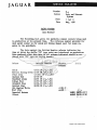
PAINT COLOURS
(All Models)
The following list gives the synthetic enamel colours being used
in production at the present time.
The reference number provided t'or
each paint colour is for Quick Air Drying Enamel used for local repairs to the paintwork.
The date against the British Domolac colours indicates tho
time at which the sut':f'i.x "CB" type paint was introduced on production.
Gars produced after this date in the colours indicated should be r~
paired with " CB" type air drying enamel.
Colour
British Domolac
Pinchin
Johnson
I. C. I.
BlaCk
Q1073 CB (14.1.60)
British Racing Green Q1076 CB (20. 1.60)
Pearl Grey
Q1129/2 CB (1. 1.60)
Carmine Red
Sherwood Green
Indigo Blue
Cotswold Blue
Corniah. Grey
Old English White
Mist Grey
Imperial Maroon
Claret
Q11 90 CB
Q1231 CB ~14.1.60l
Q1233 CB 20.1.60
Q1234 CB 20.1.60
Q1236 CB 14.1 • 60
d~
:!_i ,...
IV.:-~- ~ (~-3311)
J.8630.
~
Jt9·~ (~-5176)
f--- --;('-
Jaguar Cars Limited 2005
JAGUAR
SERVICE BULLETIN
Number N .6
Section Body & Exhaust System
Sheet 1 (of 1)
Due February, 1961
OPALESCENT PAINT COLOURS
The following are the reference numbers far the I.C.I. Delco
300 P.03l line Quick Air Drying Enamel in the new opalescent
(metallic) paint colours which were recently introduced in production.
Colour
Q.A.D.
Reference Number
Blue
J .1050
Dark Green
J .1051
Gunmetal
J .1052
Silver Grey
J .1053
Silver Blue
J .1054
Bronze
J.l055
7
Jaguar Cars Limited 2005
JAGUAR
SERVICE BULLETIN
Number N. 7
Section Body
Sheet 1 (of 1)
Date June , 1961
RUBBER DOOR BUFFERS
Wodela affected
Commencing Chass i s Numbers
R. H. Drive
L.H. Drive
105620
163583
202910
126080
176602
216650
2.4 litre :.lark 2
3.4 litre llark 2
3.8 litre :.lark 2
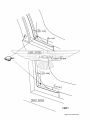
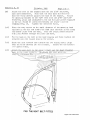
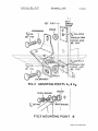
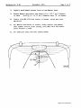
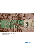
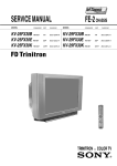
On cars with the above chassis numbers and onwards, a rubber
buffer (Part number BD.4951) is fitted to the outer rear corner of
the front and rear door sills to eliminate moveaent of the doors
when shut .
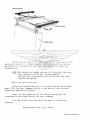
Interchangeability is n ot affected by the introduction of
the buffer which aay also b e fi tted to cars prior to the above chassis
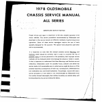
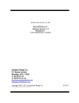
numbers if desired. To incorporate this modific a tion on such cars ,
it ia necessary to drill a 17/64" (6.74 mm) hole in the door sills as
shown in the illustration over leaf. I t may be necessary to reduce
the height of the buffer to ensure a perfect fit.
Spares Bu lletin number P. 32 refers .
WINDSCREEN GLASS
Models affected
2.4 litre :.lark 2
3.4 litre :.lark 2
3 . 8 litre Mark 2
Comaencing Chassis Numbers
R. H. Drive
L. H. Drive
108169
166308
204634
126415
177254
217419
On cars with the above chassis nuabers and onwards, toughened
glaaa windscreens have a special built-in "zone" . This special
"zone" is to enaure vision in the event of the windscreen being
shattered.
The new windacreen glass is interchangeable with the previous
glass but it should be noted that due to the introduction of the
"zoned" area the new glass is "handed" accor ding to whether the car
is L .H. Drive or R. H. Drive .
Spares Bulletin nuaber P.35 refers.
Jaguar Cars Limited 2005
~
~
17
II
4 HOLES64 OIA
I
2.011
I
Jaguar Cars Limited 2005
JAGUAR
SERVICE
BULLETIN
Number N.8.
Section Body
Sheet 1 (of 1)
Date October, 1961.
BONNET LOCK - YODIFIED TYPE
Yodels affected
Commencing Chassis Numbers
"E" Type Fixed Head Coupe
Open 2-seater
R.H. Drive
L.H. Drive
860005
885021
850092
875386
On cars with the above chassis numbers and onwards, a revised
bonnet locking system is incorporated. The bonnet is fastened and
released by means of two small levers one on either door hinge pillar.
To open the bonnet, turn the levers anti-clockwise and pull out
t o their full extent . Insert the f i ngers under the rear edge of the
b onnet, press in the safety catch and raise the bonnet. To close t he
bonnet, push the bonnet closed, then applying pressure to the top of
t he bonnet, push the lever fully home and turn clockwise. Repeat f or
t he other side of the bonne t. It is YOST IYPORTANT to ensure that the
l evers are out to their ful l extent and have not been pushed in acci dentally before attempting to close the bonnet or the bonnet may b e
damaged.
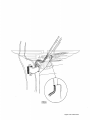
WIND NOISE
Yark 2 Yodels
In cases of complaint of wind noise from the front edges of the
front doors on Wark 2 models, it is recommended that a rubber sealing
strip is fitted to the forward edge of the doors adjacent to the top
hinge .
To fit the strip (Part Number BD.21361 (L.H.), BD.21362 (R . H.)
remove the front door capping and waist rail and pull the top of the
door trim casing away from below the window aperture. Slacken the
two screws below the no draught ventilator and pull the frame away
from the door. Using a suitable adhesive, stick the sealing strip to
the forward edge of the door so that the upper end is trapped by the no
draught ventilator frame (see illustration overleaf). Tighten the
securing screws, restick the door casing tria and refit the waist rail
and door capping.
Jaguar Cars Limited 2005
Jaguar Cars Limited 2005
JAGUAR
SERVICE BULLETIN
Number N.9.
Section Body and Exhaust
System
Sheet 1 (of 1)
Date December, 1961
EXCESSIVE HEAT IN THE DRIVING COYPARTMENT
(Yark 2 Automatic Transmission)
If trouble is experienced with excessive heat in the driving
c ompartment of Mark 2 cars fitted with automatic transmission (prior
to the fitting of the remote dipstick- Service Bulletin number FF.3)
the following checks should be made:1.
That the rubber plug blanking the dipstick hole in the gearbox
cover is in position.
2.
That
the felt blank is in position on top of the rubber plug.
It should be brought t o the attention o f luoricat ion bay
operators that both ih ese parts mus t be refit t ed corr ec tly after
checking the oil level of the automatic transmi ssion.
DOOR LOCK YODIFICATION
(Kark 2 Yodels)
If trouble is experienced with the door locks jamming when the
outside button and inside lever are operated at the same time, the
following modification should be carried out.
Remove the door casing, wood capping and plastic covering as
described in Section N "Body and Exhaust System" of the Mark 2 Service
Wanual. Wove the inner door handle into the locked position. This
action moves the plunger operating lever from behind the lock contactor.
Slacken the lock nut and unscrew the push button plunger bolt (shown
in the illustration overleaf). Discard the hexagon headed bolt and
screw the locknut onto the countersunk cross-headed screw (Part Number
8949). Screw the countersunk screw into the plunger operating lever.
The clearance between the bead of the plunger screw and the lock contactor
should be 1/32" (0.8 mm). To adjust, slacken the locknut, screw the
plunger screw in or out as required and retighten the locknut.
Refitting the plastic covering, door casing and wood capping
is the reverse of the removal procedure.
Jaguar Cars Limited 2005
Jaguar Cars Limited 2005
JAGUAR
SERVICE
BULLETIN
Number N.ll
Section Body & Exhaust
System
Sheet 1 (of 1 )
Date January, 1962
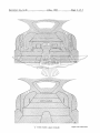
ACCIDENTAL DAUAGE TO THE FRONT FRAME
{"E" Type)
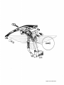
It is most important when accidental damage has been sustained
to the Front Frame that the appropriate sub-frame assembly should be
replaced. NO ATTEYPT SHOULD BE WADE TO WELD OR BRAZE REPLACEMENT
TUBES INTO THESE ASSEYBLIES NOR SHOULD HEAf IN ANY FORW BE APPLIED
IN AN EFFORT TO STRAIGHTEN THEY.
The breakdown of the Front Frame assembly is given on pages
157 to 159 of the "E" Type Spare Pa rt s Ca t a l ogue .
SEAT BELT ATTACHWENT POINTS
Commencing Chassis Numb ers
Models affected
R.H. Drive
2.4 litre Yark 2
3.4 litre Yark 2
3.8 litre Wark 2
"E" Type Open 2-s e a ter
. , (vr
"E., Type Fixed Head Cou~e
L,e.
Yark 10
\ t,.V
L.
~
( e, ....I
' '>'-·
I' L
L.H. Drive
111418
126652
158371
177753
207313
219801
850301
876359
860113
885318
From commencement of
production .
-
. . .~·
\"4 ,·.··..,.......-~
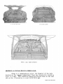
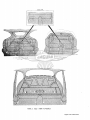
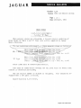
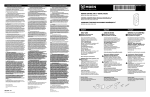
On cars with the · above cti~ssis numbers and onwards, mounting
points for the attachment of seat belt anchor brackets are provided.
The mounting points are in the positions shown overleaf and are
designed to suit a wide range of seat belt types. The pairs of holes
for floor mountings are 2!" (6 . 35 em) between centres, one hole being
a i." ( 9. 5 mm) plain clearance hole and the other being a 7/16" ( 11. 1 mm)
UNF tapped hole. The mountings holes behind the seats or on the centre
pillars are all tapped 7/16" (11.1 mm) UNF. (See illus t rations overleaf).
On cars supplied to North America, eye bolts are fitted to the
tapped holes on the floor mountings behind the front and rear seats.
/Continued overleaf ••.
Jaguar Cars Limited 2005
'
.(
TYPE FI XED HEAJ COUPE
' (TYPE OPEN 2 SEATER
MARK 2 AND
MARK 10 MODELS
Amendment to Service Bulletin Number N.lO.
Owing to a typographical error, the diameter of the hole
drilled in the luggage compartment floor was incorrectly stated as
5/16" (7.9 mm). This dimension should be altered both in the text
and on the illustration to read 15/16"(23.8 mm).
Jaguar Cars Limited 2005
JAGUAR
SERVICE BULLETIN
Number N.13 .
Section Body & Exhaust
System
Sheet 1 (of 1)
Date March, 1962
ADJUSTMENT OF
B~
CXlMPENSATOR MECHANISM
(II E" Type )
If there is evidence of the bonnet compensator mechanism
fouling the rack and pinion steering bellows, the compensator linkage
should be adjusted as follows.
Slacken the four setscrews securing the front of the appropriate
compensator linkage to the bonnet. Adjust the securing bracket to
a position where (with the bonnet closed) there is adequate clearance
between the bonnet springs and the bellows and also between the top of
the linkage and the bonnet side member. Tighten the four setscrews
and ensure that the bonnet closes correctly before securing.
- - -....
~
.....----;r---"7
OPALESCENT PAINT REFINISHING
(All Models )
Enclosed with this bulletin is a leaflet giving information on
the refinishing of paintwork on car s originally fini shed i n opalescent
colours.
Supplies and further information may be obtained by Distributors
and Dealers in the British Isles from the various branches of Brown
Brothers Lim1ted or Thompson and Brown Brothers Limited. OVerseas
Distributors and Dealers should contact their nearest I.C.I. agent.
Jaguar Cars Limited 2005
JAGUAR
SERVICE
BULLETIN
Number N.14. (2nd issue)
Section Body
Sheet 1 ( of 1 )
Date March, 1963.
JAGUAR SEAT BELTS.
ThlS bulletin supersedes the original issue of April 1962 which should
be destroyed.
Mooels affected
litre Mar·J< 2
3.4 litre Mark 2
3.8 litre Marl< 2
'E' Type Open 2-seater
Fixed Head Coupe
Mark 10
2.,4
Commencing Chassis Numbers
R.H.Urive
L.H.Drive
111418
158371
207313
126652
177753
850~01
876359
860113
885 ..H8
21~801
From commencement of proouction.
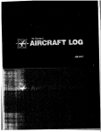
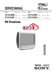
For cars with built-in seat belt anchorages, (that is, on ana
at'ter the above chassis numbers) official Jaguar seat belts will soon
be availanle. These be1ts will be marKeted solely by this company and
will be supplied only througn the J aguar Spares Divis1on.
Tne part numbers of the seat belt kits for all models are as
follows ana Wlll incluae the necessary attacnmenL bolts ana eyebolts.
Part No.
Front seat belt (lap;diagonal)
Rear seat belt (diagonal)
9212
9213
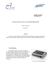
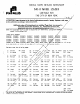
The positions of the anchorage points are shown overleaf.
Earlier cars had two holes, one plain and one tapped, at the floor
anchorage positlons; later cars have only a single 7/16" (ll.l mm)
~.N.F. tappea hole.
In either case only the t apped holes will be used
for anchorage purposes.
Note : The tapped holes in the floor are blanked off with plastic
cross heaoea screws. On the Mark 2 and Mark 10 models,
the tapped hole in each centre pillar is blanKed off with
a chrome plated escutcheon.
·<j·
Full fitting instructions will be included with each belt.
Jaguar Cars Limited 2005
--
'E'TYPf OPEN 2 >EAT~R
TYPE FIXED HEAD COUPE
r-~n1v
EAR LY
rAQ<.
MARK 2 AND
CAR~
MARK 10 MODELS
Jaguar Cars Limited 2005
tiCi\ Refinishing of
~
JAGUAR CARS
finished in Opalescent
These notes are designed to assist refinishers in obtaining
good results when repairing or refinis hing Jaguar cars finished in
Opalescent colours.
\
.,.l
A complete range of I.C.I. 'Belco' 300 Metallichrome refinish
materials (P03l-line) is available ready-mixed to match the
current range of Opalescent colo urs used on )aQuar cars. It is
well known that metallic colours require slig htly different application and colour-matching techniques from those adopted with
straight rolours, but, provided that the recommended procedure is
strictly followed, the colours in this range will be found to give
a good match to the majority of cars brought in for refinishing. The
fi nish should be thinned in the ratio of 2 parts of paint to approximately 3 parts of 'Be lco' Fas t Thinner 851-222 to a viscosity of
25-:;J seconds in a B.S./8.4 flow cup at room temperature and
applied in full wet coats. It is important t hat full wet coats be
applied; if t he finish is applied too dry, it will not develop the
characteri stic met allic pattern of the origi nal stoved film.
As in all refinis hing, minor alterations to the colour of the
refinish material are occasionally necessary to obtain an exact
match to a particular body. Such adjustments should be made by
additions of 'Belco 1 Reduced Tinters, ava ilable as follows:-
P062-990l 'Belco' Basic Reduced Black.
P062-9~ 'Belco' Basic Reduced Monastral Blue.
P062-9905 'Belco' Basic Reduced Monastral Green.
P062-99ll ' Belco' Bas ic Reduced Yellow Oxide.
P062-9914 ' Belco' Basic Reduced Deep Indian Red.
P062-99 15 'Belco' Basic Reduced Turkey Red Oxide.
*PD62-9923 'Belco' Basic Reduced Garnet Maroon
P062-9930 ' Belco' Basic Reduced Blue Lake.
P062-9940 'Belco' Basic Reduced Fast Green.
*To b• Introduced shortly.
Jaguar Cars Limited 2005
Because of their reduced strength, these tinters are particularly suitable for use with metallic finishes and the d<m:Jer of
over-tinting is greatly reduced. Even so, the ti nters should be
added with care in small amounts.
Addition of aluminium tinter is not normally necessary, but
where the refinish material requires to be made lighter or more
metallic in appearance, Alwniniwn Tinter P031-9995 may be used.
I. C.l. Refinish products, including all the materials described
above may be obtained through the various branches of Brown
Brothers Ltd. or Thomson and Brown Brothers Ltd.
Issued by IMPERIAL CHEMICAL INDUSTRIES LIMITED
PAINTS DIVISION
February, 1962
Jaguar Cars Limited 2005
SERVICE
JAGUAR
Number
BULLETIN
~.19
Section Body and Exhaust
System
Sheet 1 (of 1)
Date October, 1962
ADDITIONAL PAINT COLOUR
Quoted be Low i s the reference number for the new I.C. I. paint
colour recently introduced in production.
Q.A.D. Refe rence Number
Colour
Golden Sand
J.l066
M)[)IFJED BODY REAR FRAME
Model affected
BRACKET~
Commencing Chassis Numbers
R.H.DrJve
Mark 10
Also i ntroduced on 3
indivi dual cars .
)
)
L. H.DRNE
300981
351388
300718
351135
351263
Commencing at the above chassis numbers t he rear suspension
mount ing holes in the rear frame brackets (which are integral with
the bodf) are re-positioned to suit the new rear suspension crossbe am (See Se rvice Bulle tin K.6). It is only possible to fit the
new crossbeam (Part No. C.20174) to the bodies with the latest
r e ar frame brackets.
Spare s Bulle tin No: P. 69 refers.
Jaguar Cars Limited 2005
JAGUAR
SERVICE
BULLETIN
Number N.22.
Section Body and Exhaust System
Sheet 1 ( of 1 )
Date March, 1963.
INSTRUCTIONS FOR FITTING RECLINING MECHANISM.
TO SPECIAL ADAPTABLE TYPE
Model affected
/'
/
SEATS.
Corrrnencing Chassis NLUllbers
1/
2.4 litre Mark 2.
3.4 litre Mark 2.
3.8 l itre Mark 2.
\UINT
,./
/
R.H.Drive
L.H.Drive
115017
162688
230325
127082
179029
222338
/
Commencing ai the above chass i s numbers, the front seats of
Ma rk 2 car s can be ,tonverted to the reclining type .
//
par~·~umbers
Th<'
BD.24397
For
BD.~4432
For
I
of
'
co~1rsiong~
ts ~:
Left~~
~
r
'
.
sea
hand sea
det~ed
Ma~
at a s
in the
and ~he seat ov::
(2 pg seat) locking the seat base to the
nuts, ~d washers .(see illustration
squab,
overle
/
2 Service Manual,
ith the base
/
at the ra , protrudes frs>fu each slide tube assembly
if necessary by t.urning one of the
eleasing the.t rack pawl.
Attach the inne (short) sl~·de tube assembly to the seat base
front pivot with a clevis pin and .t hree brass washers, locating two
washers between the lugs on the tube assembly and the seat base and
the remaining washer under the split pin.
Repeat the operation to the outer (long) sli.de tube assembly
ensuring that the two halves . of the operating rod centre coupling a re
mated correctly.
1
/
/cont'd ••.••••
Jaguar Cars Limited 2005
Attach the two racks at the rear e nds of the sHde tubes to the
squab pivot points in a similar manner. Feed t he escutc heon, s pr j_ng
and washer over the operating rod. Fit the hand.les and insert the
retaining pin.
NOTE: The handles arc handed and must be fit ted with the l ever
knob towards t he front and curving downwa rds.
Lubricate all pivot points with oi l and coat the racks
lightly with grease.
Refit the seat to the car.
Locate the recessed section of the cushion s pring casing lower
edge. Slit the s eat trimming locally in the section, turn back and
secure with upholstery solution.
Lower the seat s quab and fit the cushion noting that t he
escutcheon is positioned outside the seat t rimming.
Ljft the release l ever and r a ise the squab to t he desired
position.
Spares Bulletin No. P.76. refe r s .
Jaguar Cars Limited 2005
JAGUAR
SERVICE BULLETIN
Number N.22 . (2nd i ssue)
Section Body and Exhaust Sys t em.
Sheet 1 ( of 2 )
Date May, 1964.
This Service Bulletin supersedes t he origina l issue of Mar ch, 1963
which should be destroyed ,
INSTRUCTIONS FOR FITTING RECLII'UNG IVIECH.AI\'IS:\'1
TO SPECIAL ADAIYI'ABLE TYPE FRONT SEATS.
Models affected.
Commencing chassis numbers .
2. 4 litre
R.H.Drivc.
115017
162688
230325
3 . 4 litre
3. R litre
Mark 2
Mark 2
Mark 2
L.H.Drivc .
127082
179029
222338
Colllllencing at the above chassis numbers, t he front seats
of Ma rk 2 cars can be converted t o the reclining t ype,
The part numbe rs of conversion kits are:80,24397
For Left-hand seat.
80.24432
For Right -hand seat.
Remove the front s e at as detailed in the Mark 2 Se rvice
Manual, Section M 11 Body" page M. 21 and turn the seat over with the
base uppermost.
Remove the tie rods ( 2 per seat) l ocking t he seat base to
t he squab, after extrac ting the setscrews, nuts and washers (see
illustration) .
Check that t he operating rods will pass through t he pivot
holes in s lide tube brackets .
Attach the lock spring to the locking l ever . Fit t he spri ng
with the square l oop over t he top of the lever and the circular loop
passing under the lever pivot bosses.
Feed the l e ve r be tween the slide tube brackets and hook the
spring into the two sma ll hol es .
Line up the l ever with the holes in the bracket a nd i nsert
t he operating rod as shmw• i n the illustration.
Secure the l ever to t he operating rod with an All en headed
grub sc rew ensuring tha t the scr ew registers with the ident in t he rod .
Jaguar Cars Limited 2005
/cont'J •••... ~ .•.• .
Raise the lever and tcap in the raised position with a
screwdriver.
Insert the correct sprirtg and follow with the rack. Force
the rack against the spring into the slide tube until only f.ive slots
are visible. Remove the screwdriver and lock the rack in this position.
WAR'liNG:
DUE TO THE RACK BEING UNDER CONSIDERABLE SPRING PRESSURE,
DO NOT RAISE THE LOCKING LEVER BY TURNING THE ROD UNTIL THE
ASSEJ\ffiLY OF THE SEAT
IS COMPLETED.
Check that the rack protrudes from each slide tube assembly
by an equal amount. Adjust if necessary by turning one of the operating
lever rods and releasing the rack pawl.
Attach the inner (short) slide tube assembly to the seat
base ft'ont pivot with a clev j_s pin and three brass washers, locating two
washers between the lugs on the tube assembly and the seat base and the
remaining washer under the spli.t pin.
Repeat the operation to the outer (long) slide tube assembly
ensur.ing that the two halvcs of the ope r ati ng' r od centre coupl.i ng are
mated correctly.
Attach the two racks at the r·ear ends of the slide tubes to
the s quab pivot points in a similar manner.
Feed the spring, washer and e scutcheon over the operating
rod. Fit the handle, with the lever po_inting to the front, press the
rubber washer, provided in the kit, into the square bore of the handle
before fitting and insert the retaining pin.
Fit the knob to the lever, the knob must curve downwards
when fitted and secure with the raised-headed drive screw.
Refit the seat to the car.
Locate the recessed sect.ion of the cushion spring cas.ing
lower edge. Slit the seat trimming locally in the section, turn back
and secure with upholstery solution.
Lower the scat squab and fit the cushion noting that the
escutcheon is positioned outside the seat trimming.
Lift the release lever and raise the squab to the desired
positi on.
Spares Bulletin No. P.76 Refers.
Jaguar Cars Limited 2005
Jaguar Cars Limited 2005
SERVICE
JAGUA.R
BULLETIN
Number N.23.
Section Body and Exhaust System.
Sheet 1 ( of 1 )
Date April, 1963.
MODIFIED DOOR LIGHT FRAMES.
Models affected.
Mark 2
Mark 2
Mark 2
2.4 litre
3.4 litre
3.8 litre
Commencin~
Chassis Numbers.
R.H.Drive.
L.H.Drive .
127075
179010
222289
114992
162651
230298
Commencing at the a bove chas s is numbers, a modified door
light frame incorporating f locked rubber channel inserts and a new
window glass are introduced on Mark 2 Models.
The door light frames are interchangeabl e with the existing
units provided the relevant window channel inserts and glass are
also incorporated.
<u!
Spares Bulleti n No. P.80 refers.
Jaguar Cars Limited 2005
JAGUAR
SERVICE
BULLETIN
Number N. 25.
Section Body and Exhaust System.
Sheet
of 1 )
Date October, 1963.
1 (
MODIFIED EXHAUST SYSTEM.
Models affected
Commencing chassis numbers.
R.H.Drive
'E' Type Open 2 seater
Fixed Head Coupe.
L.H.Drive.
850755
861271
879990
889096
Commencing with the above chassis numbers a modified exhaust
system which gives improved silencing is fitted.
The new_mufflers are less effective in sound absorption than
their predecessors and must not be used with the previous type of
s ilencers.
For full detail s of interchangeability see Spares Bulletin M.23.
CHURCHILL '700' BODY CHECKING AND REPAIR JIG.
(Mark
2.4/3.4 litre, Mark 2, 'E' Type and Mark 10 Models).
The Churchill '700' system for the checking and repair of
bodies has now been extended to cover the above Jaguar models.
Additional adaptors are also being developed to suit the 3.4/3.8 'S'
models.
Distributors and Dealers who require this equipment should
approach Messrs. V.L.Churchill & Co. Limited of Great South West Road,
Bedfont,Feltham, Middlesex direct.
The main feature of this equipment is its adaptability for
present and future models. The basic equipment consists of transverse
members affexed to two 'I' section beams in pre-determined positions.
Adaptors to suit various models are bolted to the transverse members
and "pick-up" the important points in the body underframe.
It is desirable that this equipment is purchased complete,
but in special circumstances Churchills are prepared to provide
drawings to enable locally purchased beams to be drilled.
/cont'd •••••••••
Jaguar Cars Limited 2005
In view of the close limits to which these beams have to be
drilled, this procedure should be adopted only in cases where it is
impossible to import the finished product.
Mark 10 Front End Jig {J.710).
A further jig for the Mark 10 model is also available.
This jig picks up at the front engine mounting points, the
engine stabiliser bracket on the bulkhead and at the bonnet hinge
points on the front crossmember. It can be used in conjunction with
the main jig or separately for the treatment of localised front end
damage.
Jaguar Cars Limited 2005
jAGUAR
SERVICE
Number
BULLETIN
N • 31 •
Section Body.
Sheet 1 ( of
Date October, 1964.
SUPPLY OF FRONT WINGS.
(Mark 2 and 3.4/3.8 'S' models)
When stocks of the present front wings are exhausted, future
supplies will be less the baffle plate which will be issued as a
separate item. The new condition of front wings will have the
suffix 'A' to the existing part number to distinguish them from the
previous condition.
Part number.
Mark 2 Mooel s
8007A
8008A
3.4/3.8 'S'
Front wing - right hand
Front wing - left hand
1013~A
10140A
Mark 2 and 3.4/3.8 'S' Models
Baffle plate - right hand
Baffle plate - left hand
10529
10530
Spares bullet.i.n No. P.135 refers.
Jaguar Cars Limited 2005
JAGUAR
SERVICE
BULLETIN
Number N.32.
Section
Body.
Sheet 1 ( of 1 )
Date December, 1964.
ADDITIONAL PAINT COLOURS.
The following are the reference numbers of Quic k Air
Drying Enamel for the new paint colours recently introduced in
production.
Colour.
Q.A.D. Reference Number.
Manufacturer.
Warwick Grey
J.932
Dark Blue ( Not- Opalescent )
J. 1080
I.C.I.
Pale Primrose.
J . 1076
I.C. I.
Pinchin-J ohnson
Jaguar Cars Limited 2005
JAGUAR
SERVICE
BUllETIN
Number N.33
Section Body
Sheet 1 (of 1 )
Date November, 1965
REAR NO DRAUGHT VENTILATOR CATCH
Models affected
2.4 litre Mark 2
3.4 litre Mark 2
3.8 litre Mark 2
'S' Type
3.8 'S' Type
4.2 Mark 10
3.4
Commencing chassis numbers
R.H.D.
L.H.D.
119204
169388
234215
184607
1BS5057
lD$1220
127824
180201
2241 61
1B26515
1B78169
1075742
Comme ncing at the above chassis numbers the t hreads of the
Rear No Draught ventilator pivot screws are coated with ,.LOCTITE"
Sealant to prevent he screws working loose.
If compraints a re received of the se sc r ews working loose on
cars previous to the above chassis numbers the t hreads should be
treated as follows:
Close the ventilator and remove rthe locknut and pivot. screw
securing the lever to the ventilator frame (note fibre washer).
Remove the two screws and detach the catch f'rom the door.
Remove the hexagon headed pi vot screw, spring and plain
washer from the underside of the catch.
Wash in cleansing solvent to remove all oil or grease .
Coa t the th1·ead with "LOCTITE,. and reassemble.
Refi t the catch and connect to the ventilator frame .
Allow time (12 hrs. approx.) for t he sealant to harden before
operating the catch.
Jaguar Cars Limited 2005
SERVICE BULLETIN
JAGUAR
Number l\.36
Section Body and Exhaust
Sheet 1 ( of 1)
Date April, 1 966
PAINT COLOURS
(All Models)
The following li st gives the paint colour range being used in current
production.
The reference numbers quoted against e ach paint colour is for QuickAir drying enamel used for local repairs to the paint work followi ng
accident damage.
REPAI R ENAMEL
SUPPLIER
OPALESCENT SILVER BLUE
II
S I LVER GREY
PRil\1ROSE
I.C.I.
I.C.I.
r.c. r.
REF. 1\C .
THINNERS
0 ..!' _ __ _ __
P031-2640
P031 - 2639
P030-3297
851/222)
851/222)
851/222)
r.c. r.
SHERWOOD GREEN
CARMEN RED
BERGER
BERGER
40.1 824
40.1 897
851/222)
851/222)
BERGER
OPALESCENT MAROON
OLD ENGLISH WHITE
WARWICK GREY
p .J.
P.J.
P.J •
CLR.7
C/768x0110
765F2615
851/222)
851/222)
851 / 222)
P.J •
BLACK
DARK BLUE
OPALESCENT DARK GREEN
II
GOLDEN SAND
G.I.P.
G.I.P.
G.I.P.
G.I.P.
CL.S030
LC. 25250
LC.24734/ M
CL. 24337/ M
8 51/222)
851/222)
851/222)
8 51 / 222)
G.I.P.
CLR.23
851 / 222
P.J •
OPALESCENT (NEW LIGHT) p J
MA.ROON
••
Jaguar Cars Limited 2005
JAGUAR
SERVICE
BULLETIN
Number i\. 37
Section Body and Exhaust
Page 1 of 3
Date December, 1966
BRITAX 'Al~OLOK' SEAT BELT
INSTRUCTIONS FOR FITTINC TO CURRENT PRODUCTION
2.4/;).4/3.8 LITRE i\'W{K 2, 3.4/3.8 'S' TYPE AND
420 CARS
The , Autolok' reel is, in all
right or 1 eft hand as rcqul r·ed.
ca~es,
mounted on t.11e centre p.illar,
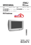
Fitting Instructions (see Illustration)
( 1)
Insert o tJ,in- bl acted screwdriver behind the tr lm casing and l-11 e
centre pilLtr ('B/C' Post).
!-'rise of'f the casing !'rom the clip
fixing, pull downwards and remove.
Knock orr tile polished wood
capping down b_x hand mtd dctoch from the pill m·.
Press out chrome
bt ~,on from wood capping.
(2)
Mark off a point l:t (12.7 mm. ) <ll)OVC the lower crlp Li.>.Jr,g hole
on the cent.l'e p.i.llnr uml d r.tll to 1 5/32'' ( l 1. 9 mm.) diameter
centr·ally in the 1 BIC' Post.
( 3)
Of'fCT up the bottom reinforcemer1t pl<l t,e (tapped 7/1 G") and mark
ol'f U1e location of the s ma.ll h ole on the ccnu·..: Villar.
The
hole should lK' on the same l~orizont al centre l.ine and for·mn·rl uf
the main hole.
Drj]J ot1t t n \ '' (6.4rrun.) diameter.
(,1)
Insert the plat,e Uwough the hinge pocket in the pillar and secure
into position witJ1 the cross-heoded drive screw supplied in the kit.
( 5)
Increase the d.i ::m1eter of tJ1c third clip fixing hole to 11/3211
( 8. 7 mm.) and using the top reinforcement plate (tapped 5/1611 )
as a template, mark off the locntion of the small hole on the
pillar.
The hole should be on the same verlical centre line
and al)Ove the main hole.
(6)
Position the plate behjnd the centre pillar face and s ecure with
the cross-headed screw.
(7)
P..ierce holes in the trim casing to corre:,;pond with the locat.i.on
of the 11/32" (8.7 mm.) and 15/32" (11.9 mm.) holes in the 'B/C'
Post.
(8)
Refit the trim casing and wooden capping.
/cont' d ••••
Jaguar Cars Limited 2005
Bulletin N. 37
December, 1 966
Page 2 o f 3
( 9)
Attach the r eel to the bracket with t-he two 5/16'' s etsct'ews ,
nuts and lockwashers.
l\"ote that the unit must be fi tted so
t hat 1:he strap un reels ag a inst the back of the bracke t .
Attach
i:!te mmmting bracket to the 'B/C ' Post wi ttl Lhe S/ 16" a nd 7 / 16"
setscrews, pl ai n and loc kwasher s ; the two d isU,nce pieces supplie d
.in t he kit s hould be inte rposed between lhe brackr·i a nd t he
trimning (Fig . 2 ).
Tighten the setsc rews fully .
( 10 )
Pl ace the wavy washer on t he s mall d iameter of the moun t ing bush
supplied in t h e kit and .i.nsert the hush into the hole in the strap
top a nchor plate from the hack.
P8ss the lrlrge plated setscrew
with plain .wash e r thro ugh t he plate and bush .
(1 1)
Fit t he bush i n t he hol e jn the wood cnpping and fully tighten the
setscrew in to the t npped boss on the pillar.
( 12)
Slide the seat forward and withd raw the t1.vo black p last.Lc plugs
fl'om the fl oor between the seat runners.
Insert tile two evehol t :'
<;J:d tighten fully .
( 13)
Attach the mai n belt to the outet' cycbol t a nd the s ho r t ( huckle)
belt to the inner eyebolt.
Re-adjust the seat position.
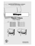
(Fig . 1, reference C).
c
FIG I THE SEAT BELT FITTED
Jaguar Cars Limited 2005
Bulletin No. N.37
December, 1966
B/C
PO~T
3 of 3
SEL'FI
TAPPING
SCREW
~;r.....,
I@ 1:
I
11
I~
.
I l~ I
I
I
l
II
--~
..
1..1J2 DIA.HOLE
THROUGH TRIM
CASING AND
B/C POST
7
~~; DIA. HOLE
THROUGH TRIM
CASING AND
B/C POST
FIG.3 MOUNTING POINT
8
Jaguar Cars Limited 2005
JAGUAR
SERVICE BULLETIN
Number N. 38
Section Body and Ex h nust Sy stem
Page 1 of
Date DecemiJer, 1 9G 6
2 .4/ 3 . 1-/3 . 8 Litre Ma r k 2
:1 . ·1 /3.R 'S' Type
Wh e n pre sen t. s tocks a re exhnus t ed, a r evi sed s erv i ce c ondit i on o f
Front Wings for Ma r k 2 a nd ' S ' Ty pe car s will be s uppl i.c d by J ngua r
S pare~ Division.
Th e new conditi on will consist of thr ee separ ate: i tems a s fol lows: (R.H. Fr ont wing a s se mbl y - Part ~o . 111 41
Mk . 2 Models ( L.H. Fron t wi ng a s sernrJl y - Phrt
~o . 111 42
{Panel - j o.in ing front wings at top - Part ='Jo . 11 1-13
''S" Type
(R.H. fronL wing as sembl y - Part No. 111 44
a ssen~ly- Part ~o . 1 1145
(Panel - joi ning f r ont wjngs nt top - Part i\o . 111 46
(L.H. front Wi ng
These item s must be ordered indiv idually.
Ca r e must be t a k en be f ore wc l <ling the top pnn e l t h a t ti-1e bonne t loc k
c ontrol i s c orrec tly posi t i oned .
The new cha ss is numbe r i s stamped on the pane l.
stamp ed when a n ew panel i ~; fi t ted.
T ll i ~
should IJe r e-
Spares Bull e t in P.l7 1- refer s .
Jaguar Cars Limited 2005
JAGUAR
,
SERVICE
Number
BULLETIN
N.43
Section Body and Exhaust
Sheet 1 or
Date March, 1 967
This Service Bulletin supersedes the original issue of Service Bulletin
N.36, dated April, 1966.
PAil\T COLOURS
(All l'vlodels)
The following list g_ivcs the paint colour range being used in current
product_ion.
The reference nt.onbel'S quoted ngainst each paint colour is for Quick-Air
drying enamel used for locRl repairs to the paintwork following accident damage.
REPAIR ENMIE L
COLOUR
·OPALESCENT SILVER BLUE
OPALESCENT SILVER GREY
PRIMROSE
DARK DLUE
SHERWOOD GREEN (Special order only)
CARJ\1El\ RED
WILLOW GREEN
SUPPLIER
I ,C . I.
I.C .I.
I.C.I.
I.C.I.
BERGER
BERGER
BERGER
OPALESCE!\'T MAROON
OLD EI\CLISH WHITE
WARWICK GREY
OPALESCENT (NEW LIGHT) ~VffiOON
p .J.
p .J.
BLACK
G.I.P.
G.I.P.
G.I.P.
G.I.P.
OPALESCENT DARK GREEN
OPALESCEl\T ('..OLDEN SMD
HO!\EY BEIGE
P.J.
P,J •
6
REF.
~0.
THINNERS NO .
~
P031-2640
P031-2639
P030-3297
P030-4647
4Dl824
851/222
851/222
851/222
851/222
I . C.I.
I. C.I.
I. c. I.
I.C, I .
4Dl888
851/222 BERGER
851/222 BERGER
851/222 BERGER
CLR7
C768X0110
765F261 5
CLR.23
851/222
851/222
851 / 222
851 /222
p . J.
p .J.
GL.5030/B
851/222
851/222
851 / 222
851/222
G.I.P.
G.I.P.
G.I. P.
G .I. P.
101897
GL. 247 3-1/M
GL.24337/M
GL.26632;V
p .J.
p .J.
1.?
Jaguar Cars Limited 2005
JAGUAR
SERVICE
Number
Section
BULLETIN
N.44
Body and Exhaust System
Sheet 1 of· 1
Date July, 196 7
BOOr
Models affected
2.4 litre Mark 2
3.4 litre Mark 2
3.8 litre Mark 2
LID LOCK
Commencing Chassis Numbers
R.H.D.
L.H.D.
121267
171582
235304
128280
181311
224709
Commencing at the above chassis numbers an improved boot lid lock
was fitted.
The lock incorporated a revised cam to prevent the boot lid from
opening when on the road.
The lock is fully inter changeable with the previous type and will
not be subject to a change of Part Number .
If complaints are received of the boot lid opening when the car
is on the road, it is recommended t hat t he n~v lock is fitted.
Future supplies of the lock will be to the new condition.
Jaguar Cars Limited 2005
July, 1967
Bulletin No. N.46
Page 3 of 3
'( TYP£
E TYPE FI XED HEAD COUPE
Jaguar Cars Limited 2005
JAGUAR
SERVICE
BULLETIN
Number N.47
Section Body and Exhaust
Page 1 of
Date J anuary, 1 968
PAINT COLOURS
(All Models)
This bulletin is issued to clarifY the information given in
Bulletin N.36 referring to Paint Colours (Quick Air-Drying Enamel).
The Reference Number quoted is the Suppliers Number which
appears on the tin.
In some instances the number may be preceded
by the letters G~ Q, or P, whjch denote gallons, quarts, or pints.
The Thinners Number as stated i s the Suppliers Number, a
common reference being used.
The Paint. Suppliers are as follows: I.C.I.
G. J.P.
-
P.J.
BERGER
Imperial Chemical Industries (Belco)
General and Industrial Paints (Glasso)
Pinchin Johnson
Berger
Two additional Paints should be added to the r ange quoted in
Bulletin N.36 as f ollows: BRITISH RACING GREEN
OONEY BEIGE
Note:
SUPPLIER
G.I.P.
G.I.P.
REF: 00.
THINNERS
GL24400
GL26632V
851/222
851/222
G.I.P.
G. J.P.
The prefix letter for G.I.P. paints in Bulletin N.36
should be GL and not C.L. or L.C.
Please mark your copy
of N.36 accordingly.
Jaguar Cars Limited 2005
JAGUAR
SERVICE
BUllETIN
Number
N.84
Body
Section
Page
Date
l of 2
November, 1971.
BONNET MASCCYI'
Models affected
2.4 I
2.4 I
3.4 I
3.4 litre Mark I
3.4 I 3.8 litre Mark 2
3.8 litre 'S' type
Difficulties in manufacturing Bonnet Mascot BD.l0954 have resulted
in it being withdrawn and supplies are no longer available.
Orders for
replacements for the above cars will therefore be executed by Jaguar Spares
Division supplying an alternative Bonnet Mascot BD.29644 which varies from
the original by the positions of the mounting studs.
Instructions for
the installat ion o~ the new Masco t are therefo r e detailed below.
INSTALLATION INSTRUCTIONS FOR BONNET MASCOT BD.29644
If the original Bonnet Mascot, part number BD.l0954, is replaced
by Mascot part number BD.29644 . the fo l lowing instructions should be
carefully followed:1. Remove original Mascot from bonnet
2. Remove front and rear portion of bonnet centre beading
3. Retouch paintwork (if necessary) where b onnet i s affected
by contact with Mascot or chrome beading.
4. Lightly mark centre line through existing fixing holes,
extending line forward by 2 in. (50 mm. ) .
5. Drill 3116 in. (4.8 mm.) hole 'A' on centre line, 1~ in. (35 mm.)
to rear of front Mascot fixing hole.
Locate new Mascot in
holes
6. Place rear chrome bead in position, mark against rear of n e w
Mascot base. Remove chrome bead and carefully cut to length.
Clean up end of bead.
7. Place front chrome bead in position, mark against front of
new Mascot base.
Remove chrome bead and carefully cut to
length.
Clean up e nd of bead.
Jaguar Cars Limited 2005
BulXetfn No. N, 84
November, 1971.
Page 2 of 2
8.
Lightly mark bonnet across front of new Mascot base.
9.
Remove Mascot and centre pop bonnet
in. (12.7 mm.) forward
of mark.
Drill
in. (3.17 mm. ) diameter hole 'B' i n bonnet.
4
10.
Locate c l i p B D . 1 1 7 1 9 and secure t o bonnet, using p o p rivet
BD. 181416
ii,
F i t Mascot and secure to bonnet, using s p e c i a l cup washer,
part number 1 7 4 4 a t front fixing, nuts UCN,119/2 and shakeproof washers C. 723/A
1
F i t modified front and rear chrome beads.
Jaguar Cars Limited 2005
JAGUAR
SERVICE
BUllETIN
Number
N.84
Body
Section
Page
Date
1 of 2
November, 1971.
BONNET MASCCYI'
Model s affected
I 3.4 litre Mark I
I 3.4 I 3. 8 litre Mark 2
3.4 I 3.8 litre 's' type
2. 4
2.4
Difficulties in manufacturing Bonnet Mascot 80.10954 have resul ted
in it being withdrawn a nd supplies a re no long er available.
Orders for
replacements for the above cars wil l t herefo r e be executed by Jaguar Spares
Di v ision supplying an alternati ve Bonne t Mascot BD.29644 which varies f r om
the orig inal by the positions o f the mount i ng studs.
Instructions for
the installat ion o~ t h e new Mas c ot ar e the refo r e det a iled bel ow.
INSTALLATION I NSTRUCTIONS FOR BONNET MASCOT BD.29644
If the original Bonnet Masc ot , part numb er BD.l0954, is replaced
b y Mascot part number 80.29644. t he f ol l o win g instructions should be
c arefully followed:1. Remove original Mascot from bonnet
2. Remove front and rear portion of bonnet centre beading
3. Retouch paintwork (if neces s ary) where b onnet i s affected
by cont act with Mascot or chrome beading .
4. Lightly mark centre line through existing fixing hole s,
extending line forward by 2 in . (50 mm. ) .
5. Drill 3116 in. ( 4 .8 mm.) hole 'A' on cen tre line, 1~ in. ( 3 5 mm.)
to rear o f front Mas cot fixing hole.
Lo cate new Mascot in
holes
6 . Place rear chr ome bead in p osition, mark agains t rear of n e w
Mascot bas e. Re mov e chrome bead and care f ully cut to length.
Clean up end of b e ad.
7. Place f r o nt chrome bead in position, mark agains t front of
new Mas cot base .
Remove chrome bead a nd carefully cut to
length.
Clean up e nd of bead.
Jaguar Cars Limited 2005
Bulletin No. N.84
November, 1971.
Page 2 nf 2
8.
Lightly mark bonnet across front of new Mascot base.
9.
Remove Mascot and centre pop bonnet! in. (12.7 mm.) forward
of mark.
Drill i in. (3.17 mm.) diameter hole 'B' in bonnet.
10.
Locate clip BD.ll719 and secure to bonnet, using pop rivet
BD.l814/6
ll.
Fit Mascot and secure to bonnet, using special cup washer,
part number 1744 at front fixing, nuts UCN.ll9/2 and shakeproof washers C.723/A
1::::.
Fit modifieo 1·ront and rear chrome beads.
Jaguar Cars Limited 2005
JAGUAR
SERVICE
BUllETIN
Number
N.84
Body
Section
Page
Date
1 of 2
November, 1971.
BONNET MASCCYI'
Model s affected
I 3.4 litre Mark I
I 3.4 I 3. 8 litre Mark 2
3.4 I 3.8 litre 's' type
2. 4
2.4
Difficulties in manufacturing Bonnet Mascot 80.10954 have resul ted
in it being withdrawn a nd supplies a re no long er available.
Orders for
replacements for the above cars wil l t herefo r e be executed by Jaguar Spares
Di v ision supplying an alternati ve Bonne t Mascot BD.29644 which varies f r om
the orig inal by the positions o f the mount i ng studs.
Instructions for
the installat ion o~ t h e new Mas c ot ar e the refo r e det a iled bel ow.
INSTALLATION I NSTRUCTIONS FOR BONNET MASCOT BD.29644
If the original Bonnet Masc ot , part numb er BD.l0954, is replaced
b y Mascot part number 80.29644. t he f ol l o win g instructions should be
c arefully followed:1. Remove original Mascot from bonnet
2. Remove front and rear portion of bonnet centre beading
3. Retouch paintwork (if neces s ary) where b onnet i s affected
by cont act with Mascot or chrome beading .
4. Lightly mark centre line through existing fixing hole s,
extending line forward by 2 in . (50 mm. ) .
5. Drill 3116 in. ( 4 .8 mm.) hole 'A' on cen tre line, 1~ in. ( 3 5 mm.)
to rear o f front Mas cot fixing hole.
Lo cate new Mascot in
holes
6 . Place rear chr ome bead in p osition, mark agains t rear of n e w
Mascot bas e. Re mov e chrome bead and care f ully cut to length.
Clean up end of b e ad.
7. Place f r o nt chrome bead in position, mark agains t front of
new Mas cot base .
Remove chrome bead a nd carefully cut to
length.
Clean up e nd of bead.
Jaguar Cars Limited 2005
BulXetfn No. N, 84
November, 1971.
Page 2 of 2
8.
Lightly mark bonnet across front of new Mascot base.
9.
Remove Mascot and centre pop bonnet
in. (12.7 mm.) forward
of mark.
Drill
in. (3.17 mm. ) diameter hole 'B' i n bonnet.
4
10.
Locate c l i p B D . 1 1 7 1 9 and secure t o bonnet, using p o p rivet
BD. 181416
ii,
F i t Mascot and secure to bonnet, using s p e c i a l cup washer,
part number 1 7 4 4 a t front fixing, nuts UCN,119/2 and shakeproof washers C. 723/A
1
F i t modified front and rear chrome beads.
Jaguar Cars Limited 2005