1
NUAL
Proper service and repair is important t o the safe, reliable operation of all
m o t o r vehicles. The service procedures recommended b y Oldsmobile and
I
I
described in this service manual are effective methods o f performing service
operations. Some o f these service o p e r a w n s require the use o f tools
specially designed f o r the purpose. The special tools should be used when
and as recommended.
I
It is important t o note that this manual contains various Warnings. and
Cautions which should be carefullv read in order t o minimize the risk of
personal injury t o service person
improper service
methods w i l l be followed which may damage the vehicle or render it unsafe.
It also is important t o understand that these Warnings. and Cautions are n o t
exhaustive. Oldsmobile could n o t possibly know, evaluate and advise the
t
I
service trade of all conceivable ways in which service might be done or o f the
possible hazardous consequences of each way. Consequent1y, Oldsmo bile has
n o t undertaken any such broad evaluation. Accordingly, anyone w h o uses a
service procedure or t o o l which is n o t recommended by Oldsmobile must
first satisfy himself thoroughly that neither his safety nor vehicle safety w i l l
be jeopardized b y the service method he selects.
\
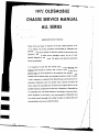
1978 OLDSMOBILE
CHASSIS SERVICE MANUAL
FOREWORD
This manual provides information on diagnosis, chassis
service procedures, adjustments, and specifications for 1978
Oldsmobiles. An understanding of the material contained
herein and in monthly issues of the Oldsmobile Service Guild
and Dealer Technical and Information Bulletins, issued when
ne cessary , will assist service personnel in properly
maintaining the quality to which Oldsmobile cars are built.
Diagnosis of all units and systems are alphabetically listed
under DIAGNOSIS in the yellow pages at the back of this
manual.
A separate Manual, the 1978 Body Service Manual, contains
body service information on all series and models used in
1978.
All information, illustrations and specifications contained in
this Manual are based on the latest product information
available at the time of publication approval. The right is
reserved to make changes at any time without notice.
CAUTION
7978 Oldsmobiles contain many parts dimensioned
in the metric system as well as in the customary
system. Many fasteners are metric and are very close
in dimension to familiar customary fasteners in the
inch system. It is important to note that, during any
maintenance procedures, replacement fasteners must
have the same measurements and strength as those
removed, whether metric or customary. (Numbers
on the heads of metric bolts and on surfaces o f
metric nuts indicate their strength. Customary bolts
use radial lines for this purpose, while most
customary nuts do not have strength markings.)
Mismatched or incorrect fasteners can result in
vehicle damage or malfunction, or possibly personal
injury. therefore, fasteners removed from the car
should be saved for re-use in the same locations
whenever possible. Where the fasteners are not
satisfactory for re-use, care should be taken to select
a replacement that matches the original. For
information and assistance, see your Oldsmobile
dealer.
PRICE:
NGlNE ELECTRICAL
MISSION CONTROL
TEN DOLLARS AND FIFTY CENTS
SERVICE DEPARTMENT
OLDSMOBILE DIVISION
GENERAL MOTORS CORPORATION
LANSING, MICHIGAN
@
1977 General Motors COW.
12-2-77
Liiho in USA
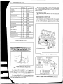
ENGINE IDENTIFICATION
The chart in Fig. OA-3 shows engine usage and
identification. All engines will be identified by litre and cubic
inch displacement, as well as the engine code letter on the
Vehicle Identification Number plate attached to the car.
Refer to Figs. OA-3 and 0 A 4 for detailed "VIN" code
information.
Fig. OA-3-Engine Identification Chart
t
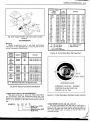
VEHICLE IDENTIFICATION NUMBERS
I
I
3V37K8M100001
DIVISIONAL CODE (OLDSI
I
'%
PLANT
SEQUENTIAL
NUMBER
MODEL YEAR
(19781
*
SERIES
CODE
NAME
SERIES
SALES
& VIN
CODE
BODY TYPE
CODE
BODY TYPE
BODY
VIN
CODE
STARFIRE SX
STARFIRE
HD
HT
D
T
OMEGA
OMEGA BROUGHAM
XB
XE
B
E
HATCHBACK COUPE
COUPE
SEDAN
17
27
69
AG
AH
AJ
AR
AR
AM
G
H
J
R
K
M
SEDAN
STATION WAGON-2-SEAT
COUPE
(CUTLASS SUPREME,
CUTLASS CALAIS &
CUTLASS SUPREME BROUGHAM)
COUPE
(CUTLASS SALON &
CUTLASS SALON BROUGHAM)
09
35
47
ENGINE
J
CODE
PLANT CODE
h
COUPE
1
PLANT
CODE
07
k
I
t
.5 LlTRE (151) 2 BBL.
L-4 (2
O
. LlTRE (305) 2 BBL.
V-8 (1
PLANT
STARTING
VIN
U
LORDSTOWN, OHIO
300001
W
WILLOW RUN, MICHIGAN
1OOOo1
M
R
D
G
2
LANSING, MICHIGAN
ARLINGTON, TEXAS
DORAVILLE.GEORGIA
FRAMINGHAM, MASS.
STE. THERESE, QUEBEC
400001
400001
40000 1
40000 1
400001
.
CUTLASS SALON
CUTLASS CRUISER
CUTLASS SALON BROUGHAM
CUTLASS SUPREME
CUTLASS CALAIS
CUTLASS SUPREME BROUGHAM
DELTA 88
DELTA 88 ROYALE
CUSTOM CRUISER
NINETY-EIGHT LUXURY
NINETY-EIGHT REGENCY
BL
BN
BQ
CV
CX
TORONADO BROUGHAM
EZ
L
N
Q
V
X
r
.
Z
STATION WAGON-2-SEAT
COUPE
SEDAN
87
35
37
69
.
BROUGHAM COUPE
57
a
(1) PRODUCED BY
(2) PRODUCED BY
(3)PRODUCED BY
(4) PRODUCED BY
GM-CHEVROLET MOTOR DIVISION
GM-PONTIAC MOTOR DIVISION
GM-OLDSMOBILE DIVISION
GM-BUICK MOTOR DIVISION
-.
Fig. OA4-Vehicle Identification Chart
M
E
X
LANSING, MICHIGAN
LINDEN, NEW JERSEY
FAIRFAX, KANSAS
iSOUTHGATE, CALIFORNIA
LANSING, MICHIGAN
1OO001
100001
100001
,
7
OA-4 GENERAL INFORMATION
The 3.8 Litre (231) WIN A) engine is identified in Fig.
OA-9. A code letter tape is also on the front of the left valve
cover as many times the other location is visually blocked by
engine accessories.
MODEL IDENTIFICATION
The 1978 models (series) and body style are identified in
Fig. OA-5.
VEHICLE IDENTIFICATION PLATE
The 1978 vehicle identification plate is located in the
left upper instrument panel. The plate is visible from outside
of the car. (Fig. OA-6) Each unit number is prefixed by
letters and numbers and have designations as shown in Fig.
OA4.
Fig. 0A-5-1978 Model Chart
I
I
OPTIONAL LOCATION
UNIT NUMBER
AND LOCATION L-4
1
I
Fig. OA-7-Unit Number Location WIN V & VIN 1 )
Fig. OA-6-Vehicle Identification Number Plate
ENGINE CODE LABEL COLOR IDENTIFICATION
1
he 2.5 Litre (151) L 4 WIN V or 1) engine unit
number location is shown in Fig. OA-7. The 5.0 Liter (305)
WIN U & H) and 5.7 Litre (350) @IN L) are identified on a
pad at the front right hand side of the cylinder block.
GREEN
YELLOW
BLUE
RED
- 4 3 LITRE ( V I N F)
- 5 7 LlTRE ( V I N R)
- 6 6 LITRE ( V I N K)
- 5 7 LITRE ( V I N N)
260 GASOLINE ENGINE
350 GASOLINE ENGINE
403 GASOLINE ENGINE
350 DIESEL ENGINE
The 4.3 Litre (260) (VIN F), 5.7 Litre (350) (VIN N &
R) and the 6.6 ILitre (403) WIN K) engines are identified by
led a--s shown
code tapes instal,,
--- .. -- in
--- Fig
- -=- OA-8
--- -.
Fig. OA-8-Engine Number Locations (vIN F, N, R & K)
GENERAL INFORMATION OA-5
Ir
TRANS. CODE
AND
MODEL
CAR
SERIES
ENGrNE
I
1
KA.
KL.
KC
JC
JC
JC
JC
JD
JD
KE
KE
LD
LD
*LA
**LH
*LKt
"LC??
""LE
LJ
WC
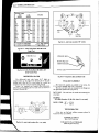
Fig. OA-9--Engine Number and Code Letter Location
(VIN A)
TRANSMISSIONS
MANUAL
Manual transmissions have 1 inch high identification
code letters on the right-hand side of case. Fig. OA-10 shows
manual transmission identification.
(350)
(350)
(350)
(350)
(350)
(350)
(350)
(350)
(350)
(350)
(350)
(350)
(350)
(350)
(350)
(350)
(350)
(350)
(350)
(350)
Starfire
Starfire
Omega
Omega
Omega
Cutlass
Cutlass
Omega
Cutlass
Cutlass
88
Cutlass
88
88
88
88
88
88
88 Wgn.
Starfire
LD5
LD5
LD5
LG3
LG4
LG3
LG4
LM1
LM1
LD5
LD5
LV8
LV8
L34
L34
L80
L80
L80
LF9
LG3
3.8
3.8
3.8
5.0
5.0
5.0
5.0
5.7
5.7
3.8
3.8
4.3
4.3
5.7
5.7
6.6
6.6
6.6
5.7
5.0
(231)
(231)
(231)
(305)
(305)
(305)
(305)
(350)
(350)
(231)
(231)
(260)
(260)
(350)
(350)
(403)
(403)
(403)
(350)
(305)
I
r
2.56 Axle Ratio
2.93 Axle Ratio
t 3.23 Axle Ratio
"f Exc. 3.23 Axle Ratio
*
**
V-6
V-6
V-6
V-8
V-8
V-8
V-8
V-8
V-8
V-6
V-6
V-8
V-8
V-8
V-8
V-8
V-8
V-8
V-8
V-8
*
Exc. High Altitude
High Altitude
Fig. OA-11-Turbo Hydra-Matic 350 Usage Chart
Fig. OA-10-Manual Transmission Identification
TURBO HYDRA-MATIC 350 TRANSMISSION
The chart in Fig. OA-11 shows the Turbo Hydra-Matic
350 transmission usage. The transmission Model and Code
Numbers are stamped on the governor cover as shown in Fig.
OA-12, or are stamped on the right vertical surface of the oil
Pan.
ALTERNATE LOCATION - NUMBER
STAMPED ON RIGHT V E R T I C E
SURFACE OF O I1 PAN
Fig. 0A-12-Turbo Hydra-Matic 350 ~
~ Number
d Location
~
l
I
EXAMPLE:
LA
021
D
78
T M o d e l Year (1978)
Shift Built
hoduction Day
Model Code
TURBO HYDRA-MATIC 200,400, AND 425
The Turbo Hydra-Matic 200,400, and 425 usage chart is
shown in Fig. OA-13. The serial number plate, Fig. OA-14 is
located on the right side of the case on the 200 and 400; the
425 serial number plate is located on the left side of the
converter housing.
/1
1
OA-6 GENERAL INFORMATION
TRANS. CODE
AND
MODEL
CAR
SERIES
ENGINE
I
2.5
2.5
3.8
4.3
4.3
5.0
5.0
5.7
5.7
5.7
5.7
5.7
6.6
6.6
6.6
PY
PY
BZ
OW*
OR**
CO
CR
OT*
OT*
OX**
OX**
OB
OD?
(200) Starfire LX6
(200) Starfire LS6
(200) Cutlass LD5
(200) Cutlass LV8
(200) Cutlass LV8
(200) Cutlass LG3
(200) Cutlass LG4
(200)88 (Exc. Wgn.)LF9
(200)
98
LF9
(200)88 (Exc. Wgn.)LF9
(200)
98
LF9
L34
(400)
98
L80
98
(400)
L80
98
(400)
OCf?
OJ
(425) Toronado L80
'f 2.56 & 2.41 Axle Ratios
.I-? 3.08 & 3.23 Axle Ratios
*
**
(151)
(151)
(231)
(260)
(260)
(305)
(305)
(350)
(350)
(350)
(350)
(350)
(403)
(403)
(403)
L4
L4
V4
V-8
V-8
V-8
V-8
V-8
V-8
VS
V-8
V-8
V-8
V-8
V-8
2
SLIP TAG
A
I
Fig. OA-16-Axle Code Location ("B" Axles)
Exc. High Altitude
High Altitude
L
Fig. OA-13-Tubo Hydra-Matic 200,400 & 425
MADE IN U. S. A.
S PREADER HOLE
Fig. OA-14-Turbo Hydra-Matic 200,400 & 425
Serial Number Plate
DIFFERENTIAL RATIOS
Fig. OA-17-Final Drive Date and Ratio Ccode
FINAL DRIVE ASSEMBLY
ratios, the
The ratio and date codes are stamped on the flange near
the right hand spreader hole. (Fig. OA-17)
DATE CODE: The code letter for month and nu.mber(s) for
actual date.
EXAMPLE:
M13=Built December 13 (M=12th. letter, I is not used).
RATIO CODE: "S" = 2.73:l
"T" = 3.07: 1
TIRE INFORMATION
A tire size, car load and inflation pressure placard is
located on every car as follows:
STARFIRE and OMEGA
Rear of left front door
Fig. OA-15-Axle Code Location (Exc. "B" Axles)
CUTLASS, 88,98 and TORONADO
Inside the glove box door
- --
MAINTENANCE SCHEDULE OB-l
SECTION 0 6
EMISSION CONTROL SYSTEM
MAINTENANCE
AND
LUBRICATION
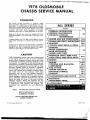
INDEX
SUBJECT
PAGE
. . . . . .
Body Lubrication
Capacities . . . . . . . . . .
. . . .
Floor Hoist Lift Points
Maintenance Schedule I . . . .
Maintenance Schedule I1 . . . .
Maintenance Schedule I11 (Diesel)
Maintenance Schedule Explanation
. . . . . . . .
Tire Rotation
. . . .
Wheel Lug Nut Torque
.
.
.
.
.
.
.
.
.
.
.
.
.
. .
. .
.
.
.
.
.
.
.
.
.
.
.
.
.
.
.
.
.
.
.
.
.
.
.
.
.
.
.
.
.
.
.
.
.
.
.
.
.
.
.
.
.
.
.
.
.
.
.
.
.
.
.
.
.
.
.
.
.
.
.
.
.
.
.
.
.
.
.
.
.
.
.
.
.
.
.
.
.
.
.
.
.
.
.
.
.
.
.
.
.
.
.
.
.
.
.
.
.
.
.
.
.
.
.
.
.
.
.
.
.
.
.
.
.
.
.
.
.
.
.
.
.
.
.
.
.
.
.
.
.
.
.
.
.
.
.
.
.
.
.
.
.
.
.
.
.
.
.
.
.
.
.
.
.
.
.
.
.
.
.
.
.
.
.
.
.
.
.
.
.
.
.
.
.
.
.
.
.
.
.
.
.
.
.
.
.
.
.
.
.
.
.
.
.
.
.
.
.
.
.
.
.
.
.
.
.
.
.
.
.
.
.
.
.
.
.
.
.
.
.
.
.
.
.
.
.
.
.
.
.
.
.
.
.
.
.
.
.
.
.
.
. . . . .OB-12
. . . . .OB-16
. . . . .OB-14
. . . . . 0B4
. . . . . OB-5
. . . . . OB-6
. OB-1 & OB-10
. . . . . OB-7
. . . . . . . . . . . . . . . . . . . . . . . . . . . . . OB-3,OB-7 & OB-11
EXPLANATION OF COMPLETE
MAINTENANCE SCHEDULES
SECTION A- LUBE
(EXC. DIESEL)
AND
This is an explanation of each of the services listed in the
complete Maintenance Schedules. Refer to Schedules I and I1
for kaintenance interval. (Figs. OB-3 and OB-4) Letters and
numbers on the schedules'an'd on this explanation are for
easy reference.
NORMAL USE OF CAR-The maintenance instructions
in the maintenance schedule are based on the assumption
that the car will be used as designed:
1. to carry passengers and cargo within the limitations
indicated on the tire placard affixed to either the edge of the
driver's door or the inside of the glove box door,
2. on reasonable road surfaces within legal operating
limits,
3. on a daily basis, as a general rule, for at least several
miles, and
4. on unleaded fuel.
Unusual operating conditions will require more frequent
maintenance as specified in the respective sections. Service
marked (*) are also required emission control maintenance
and are not repeated under the subhead Emission control
Service.
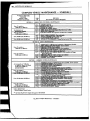
GENERAL MAINTENANCE
SCHEDULE I
SCHEDULE II
ITEM NO. AND SERVICES
A-1. CHASSIS-Lubricate all grease fittings in front
suspension and steering linkage. Lubricate transmission shift
linkage, hood latch, hood and door hinges. Lubricate parking
brake cable guides, underbody contact points and linkage.
Tie Rods . . . . . . . .
Relay Rod (Exc. Toronado)
Idler Arm (Exc. Toronado)
Upper Ball Joints
. . . .
Lower Ball Joints
. . . .
Pitman & Idler Arm (Starfire)
.
.
.
.
.
.
.
.
.
.
.
.
.
.
.
.
.
.
.
.
.
.
.
.
.
.
.
.
.
.
.
.
.
.
.
.
.
.
.
.
.2
.1
.2
.2
. . . . . . . .2
~
I1
I
A-2. FLUID LEVELS-Check level of fluid in brake
master cylinder. power steering pump. battery, engine, axle,
transmission and windshield washer.. Engine coolant should
be checked for proper level and freeze protection to at least
-35" F (-37" C) or to the lowest temperature expected
during the period of vehicle operation. Proper engine coolant
also provides corrosion protection.
Any significant fluid loss in any of these systems or
units could mean that a malfunction is developing and
corrective action should be taken immediately. A low fluid
level in the brake master cylinder front reservoir coukd also
be an indicator that the disc brake pads need replacing.
I
A-3. ENGINE OIL*-Change every 12 months or
7,500 miles (12 000 km) whichever occurs first under normal
driving conditions or each 3 months or 3,000 miles (4 8 0 0
km) when the vehcle is operated under the following
conditions: (a) driving in dusty conditions, (b) trailer pulling,
(c) extensive idling or (d) short-trip operation at freezing
.
temperatures (with engine not thoroughly warmed-up).
Fig. OB-6 shows recommended oil viscosity for
anticipated temperature range. When changing oil, consider
the anticipated temperatures for the next 4 months. SAE 5W
and 5W-20 oils are not recommended for sustained high
speed driving. SAE 30 oils may be used at temperatures
above 40" F (4" C). SAE 5W-30 is recommended for all
seasons in cars normally operated in Canada.
The dipstick is marked "Full" and "Add". The oil
level should be maintained neither going above the "Full"
Use only "first linew oils which, according to the label
on the can are (1) intended for service SE , and (2) pass car
makers' tests (including General Motors Standard GM
6136-M). The majority of the suitable oils currently available
are multi-viscosity. on-detergent and other low quality oils
SCHEDULE I
SCHEDULE I1
SCHEDULE I11
TEMPERATURE
NOTE1
RANGE ANTICIPATED
BEFORE NEXT
OIL
O I L S ARE RECOMMENDED FOR ALL SEASONS I N
SAE 5W-20
VEHICLES NORMALLY OPERATED I N CANADA.
O I L S ARE NOT RECOMMENDED FOR SUSTAINED HIGH-SPEED
DRIVING.
Fig. OB-6-Oil Viscosity Chart (Gasoline)
are specifically not recommended. The use of proper engine
oils and oil change intervals are the best assurance of
continued reliability and performance from the engine
The use of "break-in" oils, "tune-up" compounds,
''friction-reducing" compounds, etc., are not recommended.
However, there are additive supplements available that can be
GLOVE BOX MAINTENANCE SCHEDULE
GLOVE BOX MAINTENANCE SCHEDULE
GLOVE BOX MAINTENANCE SCHEDULE
-
1
Engine Family No.
on Emision Label
Option
820X2U
820X6U
840B2
840E2LU
830H2U
830H2AU
810Y2
810Y2V
810L4
810J4S
840J4U
83059
8 30M4U
830M4AU
830M4U
830M4AU
LX6
LS6
LD5
LD5
LV8
LV8
LG3
LG3
LG4
LM1
L77
LF9
L34
L34
LSO
LSO
I
Engine
Displacement 1 VIN I Carb.
GM Engine
Built By:
A11 Exc. Calif.
& Hi Altitude
High
Altitude
2 5 Litre (151)
25Litre(151)
3.8 Litre (231)
3.8 Litre (231)
4.3Litre(260)
4 3 Litre (260)
5.0 Litre (305)
S.OUtre(305)
5.0 Litre (305)
5.7 Litre (350)
5.7Litre(350)
5.7 Litre (350)
5.7 Litre (350)
5-7 Litre (350)
6.6 Litre (403)
6.6 Litre (403)
Pontiac
Pontiac
Buick
Buick
Oldsmobile
Oldsmobile
Chevrolet
Chevrolet
Chevrolet
Chevrolet
Buick
Oldsmobile
Oldsmobile
Oldsmobile
Oldsmobile
Oldsmobile
II
*
*
I1
*
I1
*
*I
*I
*
I1
*
L
I
CHANGE
SAE 5W-30
-
V
1
A
A
F
F
U
U
H
L
X
N
R
R
K
K
2 Bbl.
2Bbl.
2 Bbl.
2 Bbl.
2Bbl.
2 Bbl.
2 Bbl.
2Bbl.
4 Bbl.
4 Bbl.
4Bbl.
Diesel
4 Bbl.
4 Bbl. '
4 Bbl.
4 Bbl. -
* Engine Not Available In This Area
Fig. OB-1-Car Designation for Maintenance Schedules
*
I
*
I1
*
I
*
I
r(r
II
I11
II
rt
I1
*
1
I1
r(r
I
Calif.
*
*
11
*
n
I1
r(c
I
rk
I
r(r
I11
*
*
II
II
I
MAINTENANCE SCHEDULE 0 8 3
>
'
MAINTENANCE SERVICE
SPECIFICATIONS
(Refer To Maintenance Schedule For Intervals)
WHEEL LUG NUT TORQUE
STARFIRE; OMEGA & CUTLASS .
88 WILDS, LV8, L34 or LF9
. . .
88 W/L80, CUSTOM CRUISER & 98
TORONADO . . . . . . . . . .
CARB. MTG. BOLT/NUT (New Gasket)
. 10-14 FT. LBS.
CARB. MTG. BOLT/NUT (Re-Torque) . . . . 8 FT. LBS.
SPARK PLUG TORQUE (w/o Tapered Seat)
25 FT. LBS.
SPARK PLUG TORQUE (w/Tapered Seat)
15 FT. LBS.
. 8 0 FT. LBS.
. 80 FT. LBS.
. 100 FT. LBS.
. 130 FT. LBS.
FLUIDS AND LUBRICANTS
Power steering system and pump reservoir
Rear Axle-Standard
. . . . . . . .
. . . . . . . . . Power steering fluid 1050017 or equivalent
. . . . . . . . . . SAE80W or SAE80W-90 GL5 (SAE80W GL5 in Canada)
Final Drive . . . . . . . . . . .
Rear Axle-Limited Slip . . . . .
Manual Steering Gear . . . . . .
Manual Transmission (Exc. 5-Speed)
.
.
.
.
.
.
.
.
.
.
.
.
.
.
.
.
.
.
.
.
.
.
.
.
Brake system and master cylinder . . . . . . .
Clutch linkage (Man. Trans. only)
a. Pivot points . . . . . . . . . . . . . .
b. Push rod to clutch fork joint, and cross shaft
Manual transmission shift linkage, column shift
.
Shift linkage, floor shift . . . . . . . . . . .
Hood Latch Assembly
. . . . . . . .
a. Pivots and spring anchor
. . . . . . . . . . . . .
b. Release pawl
. . . . . . . . . . .
Hood and Door Hinges
Automatic Transmission Shift Linkage . . . . .
Chassis Lubrication . . . . . . . . . . . . .
Automatic Transmission (and 5Speed Man. Trans.)
. . . . . .
or equivalent
Lubricant 105008 1,1050527 or equivalent ,
Lubricant 1052271,1052272 or equivalent
Lubricant 1051052 or equivalent
SAESOW or SAE-80W-90 GL-5 gear lubricant
(SAE-80 GL5 in Canada) or equivalent
Delco Supreme I1 Fluid, DOT-3 Fluid or equivalent
.
.
.
.
.
.
.
.
Engine Oil
Chassis grease meeting requirements of GM 6031 -M
Chassis Grease
Engine Oil
. . . . . .
. . . . . .
Engine Oil
Chassis Grease
Engine Oil
Engine Oil
Chassis grease meeting requirements of GM 603 1-M
DEXRONB-I1 D automatic transmission fluid
or equivalent
Chassis Grease
105 1344 or equivalent
WD40 or equivalent spray lubricant
.
.
.
.
.
.
.
.
.
.
.
.
.
.
.
.
.
.
.
.
.
.
.
.
.
.
.
.
. . . .
. . . .
. . . .
. . .
.
.
.
.
.
.
.
.
.
.
.
.
.
.
.
.
.
.
.
.
. . . . . . . . . . . . . . . . . .
Parking Brake Cables
. . . . . . . . .
Front Wheel Bearings (Rear on Toronado)
Lock Cylinders . . . . . . . . . . . . . . . . . . . . .
Body Door Hinge Pins, Station Wagon Tailgate Hinge
and Linkage, Station Wagon Folding Seat, Fuel Door Hinge, Rear
. . . . . . . . . . . . . . . .
Compartment Lid Hinges
Windqhield Washer Solvent . . . . . . . . . . . . . . . .
Engine Coolant . . . . . . . . . . . . . . . . . . . . .
Engine Oil (Gasoline Engines)
Engine Oil (Diesel Engines) .
. . . . . . . . . . . . . .
. . . . . . . . . . . . . . .
Engine Oil
'
105 15 15 or equivalent
(50150 mixture of wgter and a high quality
Ethylene Glycol base anti-freeze conforming to
GM Spec. 1899-M
"SE" Engine Oil conforming to GM Specs. GM 6 136-M
"SE/CDm Engine Oil
FILTERS
TYPE (OR EQUIVALENT)
. . . . . . . . . . . . . . . . VINV,l,U,H&L,PF25;VINN,PF30;VINA,PF40;VINF,R&K,PF45
. . . . . . VIN V , A615C; VIN 1, A643C; VIN A (Starfire) A169CW, (Omega & 88) A178CW, (Cutlass) A329C;
. . . . . . . . . . . . . . . . . . . .VINH, L&F7A348C;VINU,A329C;VINN, A644C;VIN R & K , A212CW
. . . . . . . . . . . . . . . . . . . . . . . . . . . . . . . . . .VIN N, FB72
Breather Cap and valve (Diesel)
Canister-Emission Control . . . . . . . . . . . . . . . . . . . . . . . . . . . . . . . . All Exc. Diesel-70260 14
. . . . . . . . . . . . . . . . . . . . . . . . . . . . . . . VIN A, U, H & L, FR59
PCV Filter (In Air Cleaner)
. . . . . . . . . . . . . . . . . . . . . . . . . . . . . . . . VIN F , R & K, FB56
PCV Filter (In Valve Cover)
Diesel Ventilation Filter (In Valve Covers) . . . . . . . . . . . . . . . . . . . . . . . . . . . . . VIN N, 557240
. . . . . . . . . . . . . . . . . . . . . VIN V & 1, CV795C; VIN A, CV770C; VIN U, H & L, CV774C;
PCV Valve
. . . . . . . . . . . . . . . . . . . . . . . . . . . . . . . . . . . . . VIN F , CV787C; VIN R & K, CV679C
Flow Control Valve (Diesel) . . . . . . . . . . . . . . . . . . . . . . . . . . . . . . . . . . . VIN N, CV796
Carb. Fuel Inlet Filter . . . . . . . . . . . . . . . All 2BBL. (Exc. VIN F) GF470; A11 4BBL. & VIN F 2 BBL. GF471
Diesel Fuel Filter . . . . . . . . . . . . . . . . . . . . . . . . . . . . . . . . . . . . . . . . . . . 560355
. . . . . . . . . . . . . . . THM200, PF200; THM350 (exc. code SWC), PF 195; (Code SWC), PF 171;
Trans. Oil Filter
. . . . . . . . . . . . . . . . . . . . . . . . . . . . . . . . . . . . . . .THM400, PF168 ;THM425, PF169
Engineoil
Carb. Air
NOTE: For Engine Vehicle Identification Letters (VIN), see the Vehicle Identification Chart.
Fig. OB-2-Maintenance Service Specifications
j/
OB-4 MAINTENANCE SCHEDULE
INTENANCE
--
SECTION B - SAFETY MAINTENANCE
Every 12 monthsor
15,000 miles (24000 km)
Every 22,500 miles (36 000 km)
* Also an ~mBsionControl Service
** See Chart (Fig.OB-1)for engines that apply to this Schedule
4
Fig. OB-3-Complete Maintenance - Schedule I
SCHEDULE I
MAmTENANCE SCHEDULE OR5
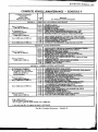
COMPLETE VEHICLE MAINTENANCE
Every 30,000 miles (48 000 km)
Every 12 months or
15,000 miles (24 000 km)
30,000 mile (48 000 km)
Every 12 months or
Also a Safety Service
* Also an Emission Control Service
t On L 4 engine, replace air cleaner assembly every 50,000 miles
- SCHEDULE II
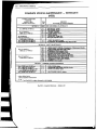
COMPLETE VEHICLE MAINTENANCE
DIESEL
- SCHEDULE Ill
Every 12 months or
9,000 miles (14 400 km)
@
Also a Safety Srvice
* Also an Emission Control Service
Fig. OBd-Complete Maintenance - Schedule iII
helpful under certain conditions. For example, if higher
detergency is required to reduce varnish and sludge deposits,
a thoroughly tested and approved super engine oil
supplement or equivalent is recommended.
A 4 . ENGINE OIL FILTER*-Replace at the first oil
change and every other oil change thereafter, if mileage
(7,500 miles - 12 000 km) is the determining factor. If time
(12 months) is the determining factor, then change oil filter
with every oil change.
A-5. TIRES-To equalize wear, rotate tires as
illustrated in Figs. OB-7 and OB-8. Adjust tire pressures as
shown on tire placard on left front door edge (glove box
door on some models). Radial tires should be rotated at first
7,500 miles (12 000 km) and then at least every 15,000 miles
(24 000 km) thereafter. Bias-belted tires should be rotated
every 7,500 miles (12 000 km). In addition to these rotation
schedules, both bias-belted and radial tires should be rotated
whenever uneven tire wear is noticed.
WHEEL LUG NUT TORQUE
STARFIRE, OMEGA & CUTLASS . . . . 8 0 FT. LBS.
88 WILDS, LV8, L34 or LF9
. . . . . . 8 0 FT. LBS.
88 W/L80, CUSTOM CRUISER & 98 . . 100 FT. LBS.
TORONADO . . . . . . . . . . . . 130 FT. LBS.
A-6. REAR AXLE OR FINAL DRNE-Change
lubricant at first 7,500 miles (1 2 000 km) on limited slip
type axles and when pulling a trailer, each 7,500 miles
(12 000 km). Change lubricant every 15,000 miles (24 000
krn) on all type rear axles or final drives when using car to
pull a trailer.
It is recommended the car be driven at least 500 miles
prior to hauling a trailer below a gross weight of 2,000 lbs.
and 1,000 miles for trailers in excess of 2,000 lbs. gross
weight.
Use of other than the above mentioned type of
lubricant in the limited slip differential may cause chatter. If
the wrong type of lubricant is used in the limited slip, it will
require draining the differential and installing the
recommended lubricant. It may be necessary to drive limited
slip equipped cars for distances of 50 miles or more to allow
the new lubricant to work through the units before the
chatter will disappear.
Always clean dirt from around plug opening before
removing the filler plug.
A-7. COOLING SYSTEM*-At 12-month or 15,000
mile (24 000 km) intervals, wash radiator.cap and filler neck
with clean water, pressure test system and radiator cap for
proper pressure holding capacity, tighten hose clamps and
inspect condition of all cooling and heater hoses. Replace
hoses if checked, swollen or otherwise deteriorated. Clean
exterior of radiator core and air conditioning condenser.
Every 24 months or 30,000 miles (48 000 km), drain, flush
and refill the cooling system with a new coolant solution.
Coolant level should be checked visually at the
see-through coolant reservoir at each engine oil change, while
the engine is at normal operating temperature. When level
drops to "ADD" mark at normal operating temperature, add
one half ethylene glycol and one half water to reservoir (not
at radiator cap) to bring to mark. (Level is OK if above
"ADD".) Under some conditions, the level may be cbserved
below the "ADD" mark on the reservoir when the system
cools and is below normal operating temperature.
A-8. WHEEL BEARINGS-Clean and repack front
wheel bearings (rear on Toronado) with high melting point
wheel bearing Lubricant 1051344 or equivalent. Add 1
ounce of lubricant to the dust cover on Toronado.
NORMAL SERVICE-Repack front wheel bearings
(rear on Toronado) at each brake relining or 30,000 miles
(48 000 km), whichever comes first.
SEVERE SERVICE-Repack front wheel bearings
(rear on Toronado) at each brake relining or 15,000 miles
(24 0 0 0 km), whichever comes first.
4 WHEELS
5 WHEELS
Fig. OB-7-Tire Rotation (Belted-Bias Tires)
SCHEDULE I1
A-9. FINAL DRIVE AXLE ROOTS AND OUTPUT
SHAFT SEALS (Toronado)-Check for damaged, torn or
leaking boots on drive axles and for leaking output shaft seal.
Replace defective parts as necessary.
SCHEDULE I1 - A-10;
SCHEDULE I - A-9
MANUAL STEERING GEAR-Check for seal
leakage around the pitman shaft and housing. If leakage is
evident (solid grease oozing out - not just oily film), it should
be corrected immediately.
4 WHEELS
5 WHEELS
Fig. OB-8-Tire Rotation (Radial Tires)
SCHEDULE I1 - A-1 1;
SCHEDULE I - A-10
CLUTCH CROSS SHAFT-At 30,000 miles
(48 000 km), remove plug in cross shaft, install lube fitting
and lube with a water resistant E.P. Chassis lubricant that
meets GM specification 603 1-M or equivalent.
1,
1
OB-8 MAINTENANCE SCHEDULE
SCHEDULE I1 - A-12;
SCHEDULE I - A-1 1
A U T O M A T I C TRANSMISSION
FLUID*-Under normal driving conditions,
change the transmission fluid and service the sump filter
every 60,000 miles (96 000 km). Under unusual conditions
such as constant driving in heavy city traffic, trailer pulling,
and commercial applications, services should be performed at
15,000 mile (24 000 km) intervals. See Section 7 for
checking procedure.
BELT TENSION
b
7
7
5/16"
WIDE
318"
WIDE
15/32"
WIDE
I
I
NEW
BELT
80 Lbs. Max.
350 N Max
150 Lbs. Max. 165 Lbs. Max.
750 N Max.
650 N Max.
USED
BELT
50 Lbs. Min.
200 N Min.
70 Lbs. Min.
300 N Min.
I
C
90 Lbs. Min.
400 N Min.
I
SECTION B- SAFETY
MAINTENANCE
SCHEDULE I
SCHEDULE II
B-1. OWNER SAFETY CHECKS-The maintenance
folder in the glove box lists several items the owner should
check and have repaired if not correct.
B-2. TIRES, WHEELS AND DISC BRAKES-Check
disc brake pads for wear and surface condition of rotors
while wheels are removed during tire rotation (See Item A-5).
Check tires for excessive wear Or damage. Make certain
wheels are not bent or cracked and that wheel nuts have been
tightened to the torque value shown in Fig. OB-2.
1
1
exhaust
B-3' EXHAUST SYSTEM*-Check
system including Catalytic Converter and nearby body areas
and trunk lid, hatchback or tailgate for broken, damaged,
missing or mispositioned parts, open seams, holes, loose
connections or other deterioration which could permit
exhaust fumes to seep into the trunk or passenger
in the
'Ompartmen Or cause a heat
pan' Dust
or water in the trunk may be an indication of a problem in
one of these areas. Any necessary corrections should be made
immediately. To help continue
exhaust 'ystem
pipes and resonators rearward of the muffler must be
replaced whenever a new muffler is installed.
I
1
(
\
B4. SUSPENSION AND STEERING-Check for
damaged, loose or missing parts, or parts showing visjble signs
of excessive wear or lack of lubrication in front and rear
suspension and steering system. Questionable parts should be
replaced without delay.
,
B-5. BRAKES AND POWER STEERING-Check
lines and hoses for proper attachment, binding, leaks, cracks,
chafing, deterioration, etc . Any questionable parts noted
should be replaced or repaired immediately. When abrasion
or wear is evident on lines or hoses, the cause must be
;
B-6. ENGINE DRIVE BELTS*-Check belts driving
fan, A.I.R. pump, generator, power steering pump and air
conditioning compressor for cracks, fraying, wear and
tension. Adjust or replace as necessary. (Fig. OB-9)
*
I
USED
COGGED
BELT
6 0 Lbs. Min.
250 N Min.
L
Fig. OB-9-Belt Tension Chart
Parking brake adjustment also should be checked whenever
drum brake linings are checked.
(NOTE: More frequent checks should be made if driving
conditions and habits result in frequent brake application.)
B-8. THROTTLE LINKAGE-Check for damaged or
missing parts, interference or binding. Any deficiencies
should be corrected without delay.
B-9. UNDERBODY-Corrosive materials used for ice
and snow removal and dust control can accumulate on the
underbody. If allowed to remain, these materials can result in
accelerated rusting and deterioration of underbody
components such as: fuel lines, frame, floor pan, exhaust
system, etc. At least once each year, preferable after a
winter's exposure, these corrosive materials should be
removed by flushing the underbody with plain water.
Particular attention
be given to cleaning out those
areas where mud and other foreign materials collect.
B-10. BUMPERS-Check the front and rear bumper
systems at 1 2-rnonth/ 15 ,OOO-mile (24 000 km) intervals to
be sure that impact protection and clearance originally
designed into these systems remain in a state of
readiness. They also should be checked whenever there is
obvious bumper misalignment, or whenever the vehicle has
been involved in a significant collision in which the bumpers
were struck, even when slight or no damage to the bumper
systemscan be seen.
SECTION C- EMISSIONS
SCHEDULE I
SCHEDULE II
SCHEDULE I - C-1 ;
SCHEDULE I1 - C-2
THERMOSTATICALLY CONTROLLED AIR
MAINTENANCE SCHEDULE OB-9
SCHEDULE I
C-2. CARBURETOR CHOKE AND HOSES-Check
choke mechanism and vacuum break for proper operation.
Any binding condition which may have developed due to
petroleum gum formation on the choke shaft or from
damage should be corrected. Check carburetor choke hoses
for proper connection, cracking, abrasion or deterioration
and correct or replace as necessary.
SCHEDULE I1
C-1. CARBURETOR CHOKE AND HOSES-Check
choke mechanism and vacuum break for proper operation.
Any binding condition which may have developed due to
petroleum gum formation on the choke shaft or from
damage should be corrected. Check carburetor choke hoses
for proper connection, cracking, abrasion or deterioration
and correct or replace as necessary. Check operation at 6
months or 7,500 miles (12 000 km), 24 months or 30,000
miles (48 000 krn), and every 12 months or 15,000 miles
(24 000 km) thereafter.
SCHEDULES I AND I1
C-3. ENGINE IDLE SPEED-Adjust engine idle
speed accurately (following the specifications shown on the
label under the hood). Adjustments must be made with test
equipment known to be accurate.
C-4. EARLY FUEL EVAPORATION (EFE)
SYSTEM-Check valve for proper operation. A binding
condition must be corrected. Check thermal vacuum switch
for proper operation. Check hoses for cracking, abrasion or
deterioration. Replace parts as necessary. (Refer to Section
6E for details.)
C-5. CARBURETOR MOUNTING- At designated
intervals, torque carburetor attaching bolts and/or nuts to
compensate for compression of the gasket. (Fig. OB-2)
C-6. VACUUM ADVANCE SYSTEM AND
HOSES-Check system for proper operation and hoses for
proper connection, cracking, abrasion or deterioration.
Replace parts as necessary.
C-7. FUEL FILTER-Replace filter (in carburetor) at
designated intervals or more frequently if clogged.
C-8. POSITIVE CRANKCASE VENTILATION
SYSTEM (PCV)-Check the PCV system for satisfactory
operation at 15,000 mile (24 000 krn) intervals, and clean
PCV filter. Replace the PCV valve at 30,000 mile (48 000
krn) intervals and blow out PCV valve hose with compressed
air. Replace deteriorated hoses.
Replace the PCV filter (if located in the air
cleaner). If PCV filter is located at valve cover, clean PCV
filter.
C-9. OXYGEN SENSOR CHANGE (If so
equipped)-Replace oxygen sensor at designated intervals.
Sensor warning flag in speedometer will be visible when
oxygen sensor change is required.
SCHEDULE I - C-10;
SCHEDULE n - c-11
VACUUM DIFFERENTIAL VALVE (VDV)
AND DIFFERENTIAL VACUUM DELAY AND
SEPARATOR VALVE (DVDSV)-Inspect valves and all
connecting hoses and lines for proper routing and secure
connections. Check for cracks, abrasions and deterioration.
Check entire system for proper operation. Replace defective
parts as necessary.
SCHEDULE I - C-11 ;
SCHEDULE I1 - C-10
SPARK PLUG AND COIL WIRES-Clean
exterior of wires; remove any evidence of corrosion on end
terminals. Inspect spark plug and coil wires for evidence of
checking, burning, or cracking of exterior insulation or other
deterioration and tight fit at distributor cap and spark plugs.
If corrsion cannot be removed or other conditions above are
noted, replace wire.
SCHEDULES I AND 11
C-12. I D L E S T O P S O L E N O I D AND/OR
DASHPOT-Check for proper operation. An inoperative
solenoid or dashpot must be replaced.
C-13. SPARK PLUGS-Replace plugs at designated
intervals with type specified in Section 6E,
C-14. TIMING AND DISTRIBUTOR CAP- Adjust
ignition timing following the specifications shown on label
under the hood. Also, carefully inspect the interior and
exterior of the distributor cap and rotor for cracks, carbon
tracking and terminal corrosion. Clean or replace as
necessary.
SCHEDULE I
C-15. CARBURETOR VACUUM BREAK-Inspect
vacuum break linkage for proper operation. A binding
condition must be corrected. Check hoses for proper
connection, cracking, abrasion or deterioration. Replace
parts as necessary.
Adjust vacuum break at specified intervals
following procedures and specifications as found in Section
6C.
SCHEDULE I1
C-15. AIR CLEANER ELEMENT-Replace the engine
air cleaner element at designated intervals. The PCV filter (on
the VIN A engine) should be replaced at the same interval.
Operation of car in dusty areas will necessitate more frequent
replacements.
(NOTE: Do not operate the engine without the air cleaner
unless temporary removal is necessary during repair or
maintenance of the car. When the air cleaner is removed,
backfiring can cause fire in the engine compartment.)
SCHEDULE I
C-16. EVAPORATION CONTROL SYSTEM
(ECS)-Check all fuel and vapor lines and hoses for proper
connections and correct routing as well as condition, Check
operation of bowl vent and purge valves where applicable.
Remove canister and check for cracks or damage. Replace
damaged or deteriorated parts as necessary. Replace filter in
lower section of canister. (See Section 6C2.)
SCHEDULE I1
C-16. CARBURETOR VACW M BREAK-Inspect
vacuum break linkage for proper operation. A binding
condition must be corrected. Check hoses for proper
connection, cracking, abrasion or deterioration. Replace
parts as necessary.
SCHEDULE I
C-17. FUEL CAP, FUEL LINES AND FUEL Tb'1 . Inspect the fuel tank, lines a . .
I
03-10 MAINTENANCE SCHEDULE
damage which could cause leaks.
2. Remove fuel cap and inspect gasket for an
even imprint from the filler neck, and any indications
of physical damage.
3. Replace any damaged or deteriorated
SECTION A- LUBE AND
GENERAL MAINTENANCE
SCHEDULE Ill (DIESEL)
SCHEDULE I1
SCHEDULE I
C-18. AIR CLEANER ELEMENT-Replace the engine
air cleaner element at designated intervals. The PCV filter (on
the VIN A , H , L & U engines) should be replaced at the same
interval. Operation of car in dusty areas will necessitate more
frequent replacements.
1
1:'
(NOTE: Do not use engine oils labeled only SE or only CD.
These oils will not give the protection and lubrication
necessary for a diesel engine. Oils meant for use only in
gasoline engines should never be used in a diesel engine; they
may cause engine damage.)
SCHEDULE I1
C-18, FUEL CAP, FUEL LINES AND FUEL TANK1. Inspect the fuel tank, lines and cap for
damage which could cause leaks.
2. Remove fuel cap and inspect gasket for an
even imprint from the filler neck, and any indications
of physical damage.
3. Replace any damaged or deteriorated
RECOMMENDED SAE VISCOSITY GRADES
(SEICD)
I
S AE 30
SAE 15W-40
EXPLANATION OF COMPLETE
DIESEL CAR MAINTENANCE
SCHEDULE Ill
i
1
This is an explanation of each of the services listed in the
complete Diesel Maintenance Schedule. Refer to Schedule 111
for maintenance interval. (Fig. OB-5)Letters and numbers on
the schedule and on this explanation are for easy reference.
NORMAL USE OF CAR-The maintenance instructions
contained in this maintenance schedule are based on the
assumption that the car will be used as designed:
1. t o carry passengers and cargo within the limitations
indicated on the tire placard affixed to either the edge of the
driver's door or the inside of the glove box door,
2. on reasonable road surfaces within legal operating
"F
-20
"C
-30
0
-20
20
-10
32
0
40
80
60
10
20
100
30
40
TEMPERATURE RANGE ANTIC IPATED BEFORE NEXT O I L CHANGE
NOTE: Use SAE 30 SEICD oil when prevailing temperatures are above 32°F (0°C).
Use SAE 15W-40 SEICD oil when prevailing temperatures drop below 32" F (0°C).
At temperatures below 0" F (-18°C). use the block heater, if so equipped. I f
circumstances do not allow the usage of a block heater. use SAE IOW-30 SEICD
oil. I f SEICD oil i s not available. use SAE 10W-30 SElCC oil. However, we
recommend using the block heater and SAE 15W-40 if at all possible. I f SAE
10W-30 oil must be used. switch back to the appropriate o i l when prevailing
temperatures rise above 0" F (-18°C).
Fig. OB-10-Oil Viscosity Chart (Diesel)
A-2. ENGINE OIL FILTER*-Replace
change.
at every oil
MAINTENANCE SCHEDULE OB-11
12 month interval (or 7,500 mile maximum)
Tie Rods . . . . . . . . . . . .
Relay Rod
...........
Idler Arm
...........
Upper Ball Joints
........
Lower Ball Joints
........
.
.
.
.
.
No. Fittings
. . .4
. . .2
. . .1
. . .2
. . . .2
A-8. WHEEL BEARINGS-Clean and repack front
wheel bearings with a lubricant as specified in the
"Recommended Fluids and Lubricants" chart. (Fig. OB-2)
NORMAL SERVICE-Repack front wheel
bearings at each brake relining or 30,000 miles (48 000
km), whichever comes first.
SEVERE SERVICE-Repack front wheel
bearings at each brake relining or 15,000 miles (24 000
krn), whichever comes first.
.
.
.
.
A-4. FLUID LEVELS-Check level of fluid in brake
master cylinder., power steering pump., battery, engine*,
axle, transmission* and windshield washer.. Engine coolant
should be checked for proper level and freeze protection to
at least -35' F (-37O C) or to the lowest temperature
expected during the period of vehicle operation." Proper
engine coolant also provides corrosion protection.
Any significant fluid loss in any of these systems
or units could mean that a malfunction is developing and
corrective action should be taken immediately. A low fluid
level in the brake master cylinder front reservoir could also
be an indicator that the disc brake pads need replacing.
A-9. A U T O M A T I C T R A N S M I S S I O N
FLUID *-Under normal driving conditions, change the
transmission fluid and service the sump filter every 60,000
miles (96 000 km). Under unusual conditions such as
constant driving in heavy city traffic, trailer pulling and
comme r cia1 applications, these services should be
performed at 15,000 mile (24 000 km) intervals. See
Section 7 for checking procedure.
SECTION B-
A-5. TIRES-To equalize wear, rotate tires as
illustrated in Figs. OB-7 and OB-8. Adjust tire pressures as
shown on tire placard which is located on the left front door
edge (glove box door on some models). Radial tires should be
rotated at first 6,000 miles (9 600 km) and then at least
every 12,000 miles (1 9 200 km) thereafter. Bias-belted tires
should be rotated every 6,000 miles (9 600 km). In addition
to these rotation schedules, both bias-belted and radial tires
should be rotated whenever uneven tire wear is noticed.
WHEEL LUG NUT TORQUE
88 WILF9 . . . . . . .
9 8 & Custom Cruiser . .
SAFETY MAINTENANCE
SCHEDULE Ill
B-1 . OWNER SAFETY CHECKS-The maintenance
folder in the glove box lists several items the owner should
check and have repaired if not correct.
. . . . . . . 8 0 FT. LBS.
. . . . . . 100 FT. LBS.
'
A-6. REAR AXLE-Change lubricant at first 6,000
miles (9 600 km) on limited-slip type axles and when
pulling a trailer, each 15,000 miles (24 000 km). Change
lubricant every 15,000 miles (24 000 km) on all standard
type rear axles when using car to pull a trailer.
A-7. COOLING SYSTEM*-At 12 -month or 15,000
mile (24 000 km) intervals, wash radiator cap and filler
neck with clean water, pressure test system and radiator cap
for proper pressure holding capacity, tighten hose clamps
and inspect condition of all cooling and heater hoses.
Replace hoses if checked, swollen or otherwise
deteriorated.
Also each 12 months or 15,000 miles (24 000
km), clean exterior of radiator core and air conditioning
condenser. Every 24 months or 30,000 miles (48 000 km)
drain, flush, and refill the cooling system with a new
coolant solution.
Coolant level should be checked visually at the
see-through coolant reservoir at each engine oil change,
while the engine is at normal operating temperature. When
level drops to "ADD" mark at normal operating
temperature, add one half ethylene glycol and one half
water to reservoir (not at radiator cap) to bring to mark.
(Level is OK if above "ADD".) Under some conditions, the
level may be observed below the "ADD" mark on the
reservoir when the system cools and is below normal
operating temperature.
(DIESEL)
B-2. TIRES, WHEELS AND DISC BRAKES-Check
disc brake pads for wear and surface condition of rotors
while wheels are removed during tire rotation (See Item A-5).
Check tires for excessive wear or damage. Make certain
wheels are not bent or cracked and that wheel nuts have been
tightened to the torque value shown in Fig. OB-2.
B-3. EXHAUST SYSTEM*-Check complete exhaust
system and nearby body areas and trunk lid or tailgate for
broken, damaged, missing or rnispositioned parts, open
seams, holes, loose connections or other deterioration which
could permit exhaust fumes to seep into the trunk or
passenger compartment or cause a heat buildup in the floor
pan. Dust or water in the trunk may be an indication of a
problem in one of these areas. Any necessary corrections
should be made immediately. To help continue integrity,
exhaust system pipes and resonators rearward of the muffler
must be replaced whenever a new muffler is installed.
B-4. SUSPENSION AND STEERING-Check for
damaged, loose or missing parts, or parts showing visible signs
of excessive wear or lack of lubrication in front and rear
suspension and steering system. Questionable parts noted
should be replaced without delay.
B-5. BRAKES AND POWER STEERING-Check
lines and hoses for proper attachment, binding, leaks, cracks,
chafing, deterioration, etc. Any questionable parts noted
should be replaced or repaired immediately. When abrasioor wear is evident on lines or hoses, the cause Pcorrected.
5
OB-12 BODY LUBRICATION
B-6. ENGINE DRIVE BELTS"-Check be1ts driving
fan, generator, power steering pump and air conditioning
compressor for cracks, fraying, wear and tension. Adjust or
replace as necessary. (Fig. OB-9)
;
HOOD LATCH
(NOTE: More frequent checks should be made if driving
conditions and habits result in frequent brake application.)
At every oil change interval, lubricate hood latch
assembly and hood hinge assembly as follows:
1, Wipe off any accumuIation of dirt or contamination
On latchparts.
2. Apply engine oil to latch and latch locking plate.
3. Apply light engine oil to all pivot points in release
as primary and secondary latch
mechanism, as
mechanisms.
4. Lubricate hood hinges with engine oil.
5 . Make hood hinge and latch mechanism f~nctional
check assure the
is
B-8. THROTTLE LINKAGE-Check for damaged or
missing parts, interference or binding. Any deficiencies
should be corrected without delay.
Use WD40 or equivalent spray lubricant as necessary for
free operation.
B-7. D R U M B R A K E S A N D P A R K I N G
BRAKE-(See Item B-2 for disc brake check.) Check drum
brake linings for wear or cracks and other internal brake
components at each wheel (drums, wheel cylinders, etc.)
Parking brake adjustment also should be checked whenever
drum brake linings are checked.
,
BODY LUBRICATION POINTS
B-9. UNDERBODY-Corrosive materials used for ice
and snow removal and dust control can accumulate on the
underbody. If allowed to remain, these materials can result in
accelerated rusting and deterioration of underbody
components such as: fuel lines, frame, floor pan, exhaust
system,etc.Atleastonceeachyear,preferableafterwinter's
exposure, these corrosive materials should be removed by
flushing the underbody with plain water. Particular attention
should be given to cleaning out those areas where mud and
other foreign materials collect.
GAS TANK
*OoR
Clean area of dirt and old lubricant. Apply a few drops
of engine oil to friction points of door hinge. work door
times and wipe
excess lubricant
INSTRUMENTPANELCOMPARTMENTDOORHrnGE
Wipe off dirt and apply a sparing amount of engine oil to
hinge frictional points. Operate door several times and wipe
excess lubricantDOOR LOCK FORK BOLT
misalignment, or whenever the vehicle has been involved in a
significant collision in which the bumpers were struck, even
when slight or no damage to the bumper system can be seen.
SECTION C- EMISSIONS
SCHEDULE Ill
(DIESEL)
C-1. FUEL FILTER-Replace fuel filter (located at
the top rear of engine) at designated intervals or more
frequently if clogged.
C-2. C R A N K C A S E V E N T I L A T I O N
SYSTEM-Check breather cap and valve assembly and
ventilation filter assemblies (both valve covers) each 6,000
miles (9 600 km).
Replace breather cap and valve assembly and
flow control valve each 30,000 miles (48 000 km).
Insepct rubber fittings and replace as required,
and clean tubes each 30,000 miles (48 000 km).
C-3. ENGINE IDLE SPEED-Adjust engine idle
speed accurately (following specifications shown on label
under the hood). Adjustments must be made with test
equipment known to be accurate.
C-4. AIR CLEANER ELEMENT-Replace the engine
air cleaner element at designated intervals. Operation of
vehicle in dusty areas will necessitate more frequent
Fig. OB-11-Door Lock Fork Bolt
FRONT DOOR HINGE ASSEMBLY
Wipe off dirt and apply a thin coat of engine oil as
indicated in Fig. OB-12. Open and close door several times to
insure that the oil has worked in effectively.
(NOTE: It is important that the contact surfaces of the
detent roller and detent lever remain free of lubricant.
BODY LUBRICATION OB-13
DOOR JAMB SWITCH
Apply a thin coat of Lubriplate or equivalent to end
surface of switch plunger.
LUBRICATE
REAR COMPARTMENT LID & LIFT GATE LOCKS
Wipe off dirt and apply engine oil to the contact surface
of the lock bolt. (Fig. OB-14) On lift gate locks, use same
lubricant on the bolt at the striker contact areas. Actuate the
lock mechanism several times and then remove excess
lubricant.
Fig. OB-12-Front Door Hinge
Lubrication at these points indicated 1 in Fig. OB-12, would
result in a sliding action instead of the desired rolling action.)
REAR DOOR HINGE ASSEMBLY
Wipe off dirt and apply engine oil as indicated in Fig.
08-13. Open and close door several times to insure that the
oil has worked in effectively.
LUBRICATE
Fig. OB-14-Rear Compartment Lock
LIFT GATE TORQUE RODS
Torque rods and hold open supports are to be lubricated
at contact areas with engine oil at car lubrication interval.
LUBRICATE
FRONT SEAT ADJUSTERS
Lubricate the front seat adjuster tracks with engine oil.
BODY RUBBER PARTS
Fig. OB-13-Rear Door Hinge
Door, hood and rear compartment rubber weatherstrips
may be kept pliable and quiet by the application of a light
coat of silicone lubricant or equivalent.
floor
at the
FLOOR HOIST L I n POINTS OB-15
FRAME CONTACT
DISTRIBUTE LOAD AND SUPPORT CAR IN A
STABLE MANNER.
.
.
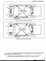
Fig. OB -17-Floor Hoist Lift Points (Cutlass, 88,98)
STABLE MANNER.
Fig. OB-18-Floor Hoist Lift Points (Toronado)
If it is necessary to use any lifting device other than the original equipment jack, such as a hydraulic, scissors or floor
jack, or a service station or dealer hoist, see illustrations above for acceptable lifting points. Lifting should only be done at the
positions indicated to prevent possible damage t o the car.
CA UT I 0N: Failure to follow the procedure outlined a@ ve ma result in unsatisfactor v
car performance, or a durability failure which may result In loss OYcontrol of the car.
i
h
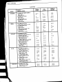
CAPACITIES OB-17
CAPACITIES (Cont 'd)
US.
MEASURE
METRIC
MEASURE
r
IMPERIAL
MEASURE
I
DIFFERENTIAL
LITRES
I
7-112" Ring Gear
8 -112" Ring Gear
8 -314" Ring Gear
Final Drive (Toronado)
1
ENGINE CRANKCASE
LITRES
3-112
4-114
4-114
4
3
3-112
3-112
3-112
QTS .
QTS .
L
I
Drain and Refill
(Exc. Toronado, Diesel and
2 5 Litre (15 1)
Toronado
Diesel (Includes Filter)
2 5 Litre (151)
When Changing Filter - Add
1
I
1-314
2
2
2
I
I
PTS .
PTS.
I
a
3-314
4-314
6-112
2 -314
1
4
5
7
3
1
3-114
4-1/4
5 -314
2-112
314
LITRES
GALS.
GALS.
70
79
68
69
18-112
20-314
18
18-114
15-112
17-112
15
15-114
79
96
103
83
98
21
25-114
27 -114
22
26
17-112
21
22 -314
18-114
2 1-314
QTS .
QTS .
1
I
FUEL TANK
q
I
I
Starfire
Omega
Cutlass
Cutlass Cruiser
88 (Sedan with L-34 &Coupe with
California L-34)
88 (Exc.Ab ove) and 98
88 and 98 Diesel
Custom Cruiser (& with Diesel)
Toronado
I
I
* TRANSMISSION (AUTOMATIC)
* 180 Automatic Transmission
*
*
*
*
LITRES
Drain and Refill
After Complete Overhaul
Turbo Hydra-Matic 200
Drain and Refill
After Complete Overhaul
Turbo Hydra-Matic 350
Drain and Refill
After Complete Overhaul
Turbo Hydra-Matic 400
Drain and Refill
After Complete Overhaul
Turbo Hydra-Matic 425
Drain and Refill
After Complete Overhaul
I
I
2 -314
4-112
3
5
2-112
4-114
2 -314
8-112
3
9
2-112
7-112
2 -314
9-112
3
10
2-112
8-114
2 -314
9-112
3
10
2-1/2
8-114
3-314
11-114
4
12
3-114
10
PTS .
PTS.
3-112
2-1/2
3-112
3
2
3
QTS .
QTS .
112
112
314
1/2
112
112
1-1/4
1-518
1-114
1-314
314
1-112
I
1
TRANSMISSION (MANUAL)
LITRES
1
L
1-314
1-1/4
1-314
3Speed
4Speed
5-Speed
I
I
POWER STEERING
LlTRES
L
Pump Only
(Starfire, Omega and Cutlass)
Complete System
Pump Only
(88,98 and Toronado)
Complete System
(Exc. 88-98 Diesel)
Complete System (88 -98 Diesel)
I
.
*
b
1
112
1
Initial Fill Capacity-See Section 7 for checking procedure. Use final quart to bring level to mark on dipstick.
For Towing,add 1-112 Litres(l-213 Qts.) DEXRON@-11D through the shifter boot.
>