1
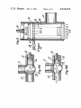
United States Patent [19]
[11]
4,318,431
Evans
[45]
Mar. 9, 1982
[54]
ELECTRONIC CONTROL SYSTEM FOR A
POUCH PACKAGING MACHINE
OTHER PUBLICATIONS
“Service Manual-Piston Filler”, FMC Corporation
[751 Inventor: Susan D. Evans, Stamford, Conn.
[73] Assignee: RJR Foods, Inc., San Francisco,
Calif.
(Ser. Nos_ 08851300 and 579B50), see p. 5.
Primary Examiner—Houston S. Bell, Jr.
Attorney, Agent, or Firm—Grover M. Myers
[57]
ABSTRACT
An electronic control system is described to control the
[2 1] Appl. No.: 214,388
operation of a positive displacement piston ?ller used
for dispensing sauce or a suitable liquid into a ?exible
pouch which is controlled in movement by means of a
Bartelt packaging machine. The electronic control sys
tem exerts‘ control over the opening and closing of a
dispensing plunger, a rotor valve and a product delivery
piston associated with the sauce ?ller apparatus. A
122]
Filed:
[51]
[52]
Int. Cl.3 .............................................. .. B65B 3/04
141/114; 141/166; 53/493; 222/70
blow-off timing sequence is further controlled to assure
[58]
Field of Search ........... .. 141/10, 1, 114, 313-317,
that a blast of pressurized air enters the dispensing head
Dec. 8, 1980
US. Cl. ...................................... .. 141/90; 141/91;
l4l/129-l92, 85~93, 98, 250-284; 53/493, 562,
of the sauce ?ller at the most optimum time to assure
407; 222/70
reliable cleaning of the top portion of the pouch prior to
sealing. The control system employs separate timers
[56]
References Cited
U.S. PATENT DOCUMENTS
2,649,674
4,081,942
8/1953
4/1978
Bartlet ................................. ., 53/562
Johnson .............................. .. 53/407
42
which serve to enable control of each of the above
described operations in one hundredths of a second to
enable precise regulation of each phase of the ?ll cycle.
17 Claims, 6 Drawing Figures
U.S. Patent
Mar. 9, 1982
Sheet 4 of4
4,318,431
_
_
E6
_
_
_
_
_
_
Qudwg?
_
_
_
_
_
_ _
_
_
_
_
_
_
UL}3.3.3..3 4
_
_
_
_ _
_
_
_
1
4,318,431
2
cognizant of the problem and do employ a blow-off
ELECTRONIC CONTROL SYSTEM FOR A POUCH
PACKAGING MACHINE
operation.
In any event, it has been a continuous problem in
sauce ?lling operations to drive the equipment at high
BACKGROUND OF THE INVENTION
This invention relates to an electronic control system
speed in order to ?ll as many pouches per minute as
possible, and to further assure that when operation oc
for use with apparatus for ?lling ?exible pouches with a
curs at high speed, that the blow-off is implemented at
product.
the proper time in the cycle. Essentially, if blow-off
The use of pouches which are fabricated from a ?exi
ble material such as a suitable plastic-foil laminate is
occurs too early or too late in the cycle, its effectiveness
well known in the art. In particular, this technique has
been employed with food products and the canning
industry is fully cognizant of many problems and solu
tions in regard to ?lling a pouch or container with food
is substantially reduced.
In prior art sauce ?lling operations, a useful mecha
nism which is available has been referred to as the
RAQUE ?ller. The Raque ?ller apparatus is located at
a ?lling station location associated with a Bartelt ma
in a relatively automated procedure. In regard to this, 5 chine. The ?ller employs a hopper which contains a
there exists many patents which show and describe the
sauce. The sauce is retracted from the hopper through a
typical problems involved in processing and packaging
food in ?exible pouches.
rotor valve by means of a product piston and eventually
Perhaps one of the most well known machines for
performing such an operation is the subject matter of
US. Pat. No. 2,649,674 issued on Aug. 25, 1953 to H. L.
Bartelt entitled “PACKAGING MACHINE”. This
machine has been employed extensively in the packag
ing industry. In this machine, the pouches are formed
from a strip of material and the formed pouches are
advanced through various ?lling stations where a prod
uct is introduced into the pouches. After product intro
dispensed by means of a dispensing piston. The Raque
?ller is controlled in operation by a completely pneu
matic system. Essentially, the control system uses pres
surized air to perform all logic operations. Air logic has
been widely employed in conjunction with packaging
operations and has been extensively used with the
Raque ?ller.
There are many disadvantages in regard to using air
logic in food processing and especially where a liquid as
a sauce is being dispensed. As one can imagine, impuri
ties in the air can jam ?lters and mufflers associated
with such systems, thus causing many failures and re
ductions in air pressure. Apart from these consider
ations is the fact that air logic operates at relatively slow
speeds
which are a function of the velocity of a sound
tively long shelf life. The ?nal operation requires seal
pressure wave. Accordingly, the systems do not permit
ing the pouch to thereby contain the ?nal food product.
The “BARTELT” machine, as indicated, is an ex 35 rapid pouch ?lling operations and are dif?cult to con
trol in regaard to timing and operation.
tremely ef?cient and reliable apparatus and is described
By employing an electronic system, one can achieve
in detail in the above noted patent.
~
more rapid operation and relative immunity from many
Patents such as US. Pat. No. 4,081,942 issued on Apr.
problems associated with air logic. However, electronic
4, 1978 and entitled “MACHINE AND METHOD
control of such apparatus is also extremely dif?cult to
FOR FILLING, INTRODUCING STEAM INTO,
duction by one or more ?lling stations, the pouches are
advanced to other locations where steam may be intro
duced in order to remove air from the pouch and'to
enable the product to be packaged in an oxygen free
environment to enable the product to possess a rela
AND SEALING FLEXIBLE POUCHES” assigned
implement due to the fact that the packing machine
such as the Bartelt machine is not synchronized to the
operation of the ?lling station and if one desires to
achieve more rapid operation, one has to be assured that
tus which is employed in conjunction with such ma
chines to increase the ef?ciency and provide desired 45 the entire ?lling sequence will occur within. a predeter
mined interval and must occur according to the operat
operating characteristics.
.
to the Rexham Corporation of New York as well as
many other patents describe various additional appara
In any event, depending upon the nature of the prod
uct which is being packaged, one experiences many
different types of problems. In particular, such ma
chines have been employed for packaging sauce type
food products in pouches. It is a major desire of any
packaging operation to ?ll the pouches or containers as
rapidly as possible, while further assuring that the
ing characteristics of the packaging machine.
proper quantity of food is emplaced in each pouch. In
conjunction with such desired operating characteristics,
is the further problem of providing a good seal for such
packaging machine and which system is adapted to
pouches when food materials such as liquids or sauces
are introduced into the ?exible pouches.
As is known in the art, the nature of the retort pouch
is such that the seal qualtity is critical. Top seal accept
ability is affected by the presence of blemishes from
occluded drops of liquid. Such blemishes can occur
from splattered sauce or condensed steam. In a sauce
In order to accomplish electronic control, the appara
tus must be capable of directly inferfacing with existing
packaging machines to assure reliable and optimum
operation. Hence, it is a general aim of the present in
vention to provide a new and improved electronic con
trol system to be used in conjunction with a pouch
control the operation of a sauce ?ller apparatus to pro
vide a system capable of ?lling pouches with sauces or
liquids at relatively high rates.
A further object of the present system is to opti
mumly control blow-off during a ?lling cycle to assure
an acceptable seal quality for the pouch.
BRIEF DESCRIPTION OF THE INVENTION
The invention is a sauce ?ller control apparatus for
?lling operation, the droplets of sauce which may effect
controlling the sequence of operation of a ?lling appara
the seal quality can be minimized by employing a prop 65 tus having product means for receiving and expelling
erly timed blast of air at the dispenser tip. This is re
the material to be dispensed, dispensing means for de
ferred to in the art as blow-off. The prior art techniques
positing the remaining material, valve means selectively
for introducing sauce or a liquid into a retort pouch are
connecting the product means with a material source
3
4,318,431
when the valve is in a ?ll position and with the dispens
ing means when the valve is in a dispensing position,
and actuating means responsive to electrical signals for
4
The pouch 10 may be fabricated during the operation
of the packaging machine. In most respects, the packag
ing machine is similar in construction to that machine
disclosed in US. Pat. No. 2,649,674 (Bartelt) and thus
controlling the product means, dispensing means and
valve means. The control apparatus comprises a ?rst
certain elements of the machine will not be described in
detail as one can ascertain the complete operation of the
timing means responsive to an initiating electrical signal
packaging machine by reference to the cited patent.
As indicated in FIG. 1, it is suf?cient to state that
each pouch 10 is adapted to be gripped releasably at its
for providing a ?rst electrical signal at the end of a ?rst
time interval following receipt of the initiating signal; a
?rst circuit means for supplying the ?rst signal to the
actuating means to cause the product means to assume
side margins by leading and trailing clamps 13 and 14
its receiving position, a second timing means responsive
to the ?rst signal for providing a second electrical signal
at the end of a second time interval following receipt of
which are carried on a chain conveyor 15. The chain
conveyor 15 is adapted to be advanced by a suitable
drive mechanism as explained in the above noted patent.
the ?rst signal; a second circuit means for supplying the
As the chain 15 is advanced, the pouches 10 are moved
second signal to the actuating means to cause the valve 15 into and momentarily dwell at a series of horizontally
means to assume its dispensing position; trigger circuit
spaced stations where packaging operations as ?lling,
means responsive to the second signal and an externally
steaming and sealing are performed on the pouches. In
supplied signal for supplying a triggering signal to cause
the present instance, the pouches 10 are advanced in
said dispensing means to open to a receiving position; a
spaced edgewiwse relation and are held with their open
third timing means responsive to the triggering signal
for providing a third electrical signal at the end of a
third time interval following receipt of the triggering
20
ends facing upwardly.
Located above the central pouch 10 is a sauce ?ller
location 20. The sauce ?ller is a well known Raque ?ller
signal; a third circuit means for supplying the third
whose operation is fully known to those skilled in the
signal to the actuating means to cause said product
art
and which will be briefly described herein.
25
means to assume its expelling position; a fourth timing
There is shown a main hopper 21 which acts as a
means responsive to the third signal for providing a
reservoir for a liquid or sauce 22. The hopper 21 is of a
fourth electrical signal and a reset electrical signal to
truncated cone con?guration having a narrow bottom
reset all of the timing means at the end of a fourth time
portion directed into a rotor valve 24. The rotor valve
interval following receipt of the third signal; a fourth 30 24 is shown in detail in FIG. 4A and FIG. 4B. The rotor
circuit means for supplying the fourth signal to the
valve, when rotated to a ?ll position, shown in FIG. 4A
actuating means to cause the dispensing means to as
sume a non4receiving position and to cause the valve
means to assume its ?ll position and to the ?rst timing
means as the initiating signal.
will enable communication between the hopper 21 and
a product cylinder 26. When rotated to a dispensing
position shown in FIG. 4B the rotor valve enables com
35 munication between the product cylinder 26 and a dis
pensing tube 29. The rotor valve 24, as above described,
has the inlet, outlet and ?ll apertures arranged in a “T”
Above-mentioned and other features and objects of
con?guration. As indicated, such valves are well known
this invention will become more apparent by reference
in the art. In the present invention the positional control
to the following description taken in conjunction with 40 of the valve is afforded by a stepper motor or coil,
the accompanying drawings, in which:
which upon reception of a suitable biasing signal, will
FIG. 1 is a partial perspective and schematic view of
actuate a valve to admit pressurized air to the Raque
a pouch packaging machine employing an electronic
supplied air motor to move the valve into any one of its
control system for a sauce ?lling operation;
operating positions.
FIG. 2 is an electrical schematic diagram of the elec 45
Shown coupled to the inlet port 240 of the rotor
tronic timing and control logic according to this inven
valve 24 is the product cylinder 26 having located
therein a product piston 27. The piston 27 is coupled to
tron;
FIG. 3 is a schematic diagram of a blow-off control
a piston rod 28 and is controlled by the product piston
BRIEF DESCRIPTION OF THE DRAWINGS
circuit according to this invention;
FIG. 4A is a detailed schematic drawing of the rotor
solenoid and associated valve and air motor 31. As is
known, the piston 27 can be in a retracted receiving
position as shown or in an extending expelling position
valve shown in FIG. 1 in its ?ll position;
FIG. 4B is a detailed schematic drawing of the rotor
(shown in dashed lines). The piston 27 will traverse
valve shown in FIG. 1 in its dispensing position; and
from the extended to the retracted position upon appli
FIG. 5 is a detailed schematic drawing of the dispens
cation of a suitable potential to the solenoid 30.
ing plunger shown in FIG. 1 in its non-receiving, or 55
Coupled to the outlet port of the rotor valve 24 is the
dispensing position.
dispensing tube 29. The tube 29 is fabricated from a
?exible hose material and provides an output path for
DETAILED DESCRIPTION OF THE
receiving product, as the sauce from the product dis
INVENTION
pensing cylinder 26, as will be described.
Shown in the drawings for purposes of illustration, 60
The dispensing tube 29 is coupled to an input port of
the invention is embodied in a packaging machine for
a dispensing head 30. The dispensing head 30 is part of
forming ?lling and sealing pouch packages such as 10.
the Raque sauce ?ller. Accordingly the dispensing head
The pouch 10 is usually made from a single or compos
is controlled to move in the vertical direction as indi
ite sheet of ?exible material such as a suitable plastic as
cated by arrows 32. When the dispensing head 30 is
a polyole?n which may contain a middle laminate of 65 moved downwardly, the opened bottom end 34 moves
aluminum foil with an outer laminate of a polyester.
into the open top of the pouch 10. As indicated above,
The fabrication and composition of pouches as 10 are
the vertical movement of the dispensing head is strictly
extremely well known in the ?eld.
under control of the packaging machine through a cam
5
4,318,431
shaft and cam follower as described in the above noted
patent.
Located within the dispensing head is a dispensing
plunger 34, shown in detail in FIG. 5. The plunger 34 is
pouch is positioned below the dispensing head and the
operation is repeated, as will be described, for each
pouch carried by the chain conveyor system associated
coupled via a suitable rod 35 to a solenoid coil and an
associated valve and air motor 36 referenced as dispense
plunger. The dispensing plunger 34 has a central aper
ture 38 through which a blast of pressurized air is di
rected during a blow-off procedure, as will be ex
plained.
6
aperture 38 and serves to force any remaining liquid
droplets to be directed into the pouch.
The above described operation occurs when the
with the Bartelt machine.
Referring to FIG. 2, there is shown an electrical
schematic diagram of the electronic timing and control
10 logic 50 depicted in FIG. 1. Where applicable, similar
reference numerals have been retained to designate
Located in a sidewall of the dispensing head 30 is an
inlet aperture 40 which is coupled via a ?exible hose 41
similar functioning parts.
In the schematic, two parallel lines represent a nor
to a source of pressurized air 42. A valve 43 under the
mally opened contact, while two parallel lines with a
transverse line drawn through represent a normally
control of the electronic system to be described pro
vides the timing for the blow-off operation and hence,
determines the duration of the opening of the valve 43,
closed contact.
The symbols for indicating a relay coil are nCR,
where N is a positive integer. A contact associated with
Shown located to the left of the central pouch 10 is a
that coil is designated as nCRx, where x is a positive
proximity switch 44 also designated as CRF-2. As will
integer. A solid state relay is indicated as nSSR with a
be described, this switch may be a microswitch and is
contact of that relay indicated as NSSRx. A timer is
activated by a pouch which enters the area at which the
depicted as nTR with a contact of the timer indicated as
dispensing head 30 is located. The switch 44 serves to
nTRx. Thus, in referring to FIG. 2, the top solid state
aid in controlling the sequence of operations to be de
relay is designated as ISSR as compared to 2SSR and
scribed.
25 3SSR. A contact relay ISSR is designated as 1SSR1 and
A further switch 45 designated as LSSF is also
is normally opened. In the embodiment described, it
shown. The switch 45 is a limit switch and is operated
will be assumed that the machine advances the pouches
from the main cam shaft of the Bartelt machine and
from station to station once each second.
operates in relation to the speed of the machine to pro
As can be seen from FIG. 2, 1SSR is in series with
vide a limit operation indicative of a pouch being within
contact 2CR1 which is normally closed and which is
the ?lling station area. This switch, as will be further
associated with relay coil 2CR. A timer 1TR is depicted
described, also controls the sequence of operations to be
by a circle and its contact is designated as lTRl. Next
as will be described.
performed by the electronic timing and control logic.
to this contact is a designation 00x. Since contact 1TR1
As seen from FIG. 1, both switches 44 and 45 inter
is controlled by the timer lTR, the designation 00x is
face with the electronic timing and control logic mod 35 determined as follows: Contact lTR 1 is a normally
ule 50. As will be explained, the module 50 provides an
opened contact and hence, the ?rst 0 indicates this.
output which controls the blow-off time via valve 43, ' When the timer is running, the second 0 indicates that
provides an output which controls the rotor valve 24,
the contact is also normally opened. When the timer
runs out, the contact is closed and hence, the third
piston solenoid 31 and the dispenser plunger solenoid 40 symbol being x represents contact closure. This termi
36.
nology is used beneath each contact which is timer
Also depicted in FIG. 1 is a manual switch 51 desig
controlled.
nated as on-off or CRST. In order to provide the timing
The above noted nomenclature has been employed in
and control sequence, the switch 51 is in its closed posi
lieu of numbers to enable one to clearly follow the
provides a further output which controls the product
tion during system operation.
With the above general description of the apparatus
in mind, it is believed that an explanation of the basic
45
system operation, which otherwise would be extremely
dif?cult.
As seen from FIG. 2, the control coils for the dis
penser plunger solenoid 36, the rotor valve 24 and the
product piston 31 are depicted by a resistor notation. It
sequence involved is warranted.
As one can ascertain, it is an object of the ?lling
operation to insert a predetermined amount of sauce or
is indicated at the on set that based on the well known
liquid 22 into the pouch 10. In order to do so the follow
ing minimum operations must occur:
The product cylinder, at a suitable time in the se
quence, must be loaded with product through the rotor
operation of such components, one skilled in the art will
understand from this circuit and control diagram how
valve. The product piston 27, discharges the product
from the product cylinder 26. When the rotor valve 24
is properly positioned, the product piston 27 moves to
its extended position to push or force the product
charge into the output dispensing tube 27 and thus into
the dispensing head 30. At this time, the bottom of the
dispensing head 30 is within the pouch 10. The dispens
ing plunger now operates to move to its dashed line
position to push the remainder of the product charge
into the pouch. When the dispensing plunger is moved
55
these mechanical components are, in fact, reliably and
accurately controlled by the electronic circuitry to be
described.
In order to clarify operating procedure, the function
of the electronic circuitry depicted in FIG. 2 will be
described in conjunction with the mechanical compo
nents depicted in FIG. 1 so that there is a complete
understanding of the system operation and control.
We will assume for present purposes that all power is
off and the packaging machine is not operating. Under
these conditions, the dispensing plunger 36 is in the up
position, the rotor valve 24 is in the dispensing position,
to the dashed line position, (shown in detail in FIG. 5) 65 and the product piston 30 is in the extended, expel posi
tion (dashed). Now assume that power is applied.
the tube 29 to head 30 is blocked. The blow-off valve is
operated and a blast of air is directed into the dispensing
head via aperture 40. The blast is directed through
In FIG. 2, a voltage appears between terminals 1 and
0. This voltage causes the following action to occur:
7
4,318,431
Power is applied from the 1 terminal through the nor
8
machine has moved the dispensing head 30 down and its
bottom end is within the pouch 10. As this occurs,
mally closed contact 4TR1 (xxO). The power through
this contact is directed via line 60 to the various circuit
switch LSSF is opened by the Bartelt machine.
components. Line 61 is obtained above contact 4TR1
Relay coil 2CR also operates when the above connec
and is directed to terminals 63. The 0 side of the power 5 tion is made. This opens contact 2CR1 and hence, deac
line is directed to line 64 which provides terminal
tivates ISSR. The deactivation of lSSR opens contact
power to one side of all circuit components.
1SSR1 which causes the dispensing plunger 36 to move
Thus, as can be seen from FIG. 2, the piston solenoid
to its receiving position, opening the inlet to the tube 29.
31 is in series with contact 3SSR1 between terminals 64
The timer 3TR, as operating, allows enough time to
and 63. In the same manner, the rotor coil 24 is in series
assure that the dispensing plunger is moved up. The
with contact 2SSR1 between terminals 64 and 63 as is
circuitry carrying the signal from the machine activates
the dispenser coil 36 which is in series with contact
the timer 3TR and in effect acts as a trigger circuit to
ISSRl. All other components are in series between
coordinate the ?ller with the Bartelt machine operation.
terminals 64 and 60 through contact 4TR1.
As can be seen, during the above procedure, the rotor
When power is applied, switch 51 which is the on/off l5 valve remains in the dispensing position.
switch CRST is manually closed and remains closed
3TR has a timing cycle which permits it to run for
during the entire operating sequence.
approximately 0.23 seconds. When it times out, contact
From FIG. 2, it is immediately seen that solid state
3TR1 closes, thus activating timer 4TR and relay coil
relay 1SSR operates through the normally closed
SCR. When 5CR is energized, relay 3SSR opens caus
contact 2CR1. This closes contact 1SSR1 which causes
ing the product piston 27 to extend to thus push product
the dispensing plunger 36 to operate. The dispensing
plunger 36 operates to the discharge position shown in
into the dispensing tube 29 via the rotor valve 24, and
into the pouch through the dispensing head 30. When
4TR times out, contact 4TR1 in series with line 60
opens, which automatically resets all timers as lTR,
2TR, 3TR and 4TR by removing power from the
dashed lines in FIG. 1. Due to the fact that 4CR1 is
closed, then solid state relay 2SSR is also operated. The
operation of this relay closes contact 2SSR1 which is in
series with the rotor coil 24. This causes the rotor to
source.
move to its ?ll position.
Also shown across contacts CRF-2, LSSF and CRST
The timer lTR operates as soon as power is supplied.
is a switch designated as ?ll jog. As one can ascertain, if
The timer may be a solid state timer which is available
this switch is manually operated, it will bypass the func
from many manufacturers and provides a time out se 30 tions implemented by the closure of CRF-2 and LSSF
quence of one hundred milliseconds or 0.1 seconds.
and hence, an operator, by the manual opening and
Essentially, the timer lTR allows the rotor valve to
turn to its ?ll position and allows the dispensing plunger
closing of the ?ll jog switch, can dispense a charge of
36 to move to its down position. When the timer lTR
runs out, contact lTRl closes. This activates 3SSR via
may be necessary due to a system failure or for low
contact 5CR1 and lTRl and activates a second timer
2TR. Upon activation of 3SSR, contact 3SSR1 closes.
4TR resets all timers including itself and hence,
power is again applied to the circuit which immediately
This moves the product piston 27 to its retracted, re
ceiving position. When piston 27 moves to the retract
causes the above noted sequence to start all over again
as above described.
position, it draws the product charge from the hopper
21 into the product cylinder 26 through the rotor valve
24. The time 2TR is set for 0.18 seconds which assures
that the product piston 27 retracts and hence, draws a
proper charge into the cylinder 26. At the end of the
time out afforded by 2TR, contact 2TR1 closes. This
immediately activates relay 4CR which opens contact
4CR] to deactivate relay 2SSR and hence, opens
contact 2SSR1 which in turn causes the rotor valve to
move to the dispensing position.
In the meantime, the pouches 10 are moving during
the above described operation, but as one can ascertain,
product into the pouch. In a manual mode, this feature
speed production.
40
As indicated during the ?rst step, which is analogous
to power coming on by the closure of contact 4TR1
again, the following sequence occurs:
The solid state relay ISSR is energized and closes
contact 1SSR1 which moves the dispensing plunger in
45 the down direction. That closes the entrance to the
dispensing head 30 and deposits the remaining sauce
into the pouch. As seen from FIG. 1, when the dispens
ing plunger is in the dashed line position, the dispensing
head 30 is within the pouch 10 by the action of the
Bartelt machine. When the dispensing plunger is in the
down position, blow-off should occur to obtain opti
the product cylinder 26 has a complete product charge
and the rotor is in the dispensing position. At this point
in time, a pouch which is being moved by the conveyor
belt will activate the proximity switch CRF-2. The
mum removal of the droplets of liquid.
In order to exactly control the blow-off sequence, the
signal labelled blow-off of FIG. 2 is shown in FIG. 3.
55 When 4TR times out and opens 4TR1, the relay 1CR is
switch LSSF is then activated by the Bartelt machine
deenergized. That closes normally closed contact 1CR1
which is a completely normal condition and hence, both
which begins the timer lBTR running by closing the
CRF-2 and LSSF are closed. The closure of LSSF is a
separately energized 24 V DC circuit 65. This timer
momentary closure and occurs when the dispensing
lBTR essentially runs in parallel with timer 1TR and
head is being moved downwardly to indicate that a 60 blow-off does not begins until timer lBTR times out,
pouch is in the position to be ?lled. The Bartelt machine
which is manifested by an adjustable delay time be
provides this indication.
’
tween timer lTR and lBTR, to give the dispensing
In any event, as soon as switch LSSF closes, relay
plunger time to descend. As soon as timer lBTR times
coil 3CR receives power through the series switches
out, contact lBTRl closes and closes the separately
CRST, LSSF, CRF-2 and 2TR1 which is closed due to 65 energized 24 V DC circuit 66, upon which timer 2BTR
the time out of 2TR. Relay 3CR latches through its own
begins to time out. As soon as timer 2BTR begins to run
contact 3CR1. This immediately activates timer 3TR to
to commence timing out, contact 2BTR1 closes which
begin a new timing mode. When LSSF is operated, the
activates the solid state relay BSSR. The activation of
9
4,318,431
solid state relay BSSR closes contact BSSRI and acti
vates the air solenoid 43 to allow a blast of air to be
directed through the aperture 38 within the dispensing
plunger 34. This immediately causes a blast of air to be
directed through the aperture 38 when the dispensing
plunger is in the down position.
Thus, in the interval before 2BTR times out, a blast of
air is directed into the dispensing head and through the
aperture in the dispensing plunger, as shown in FIG. 5.
As soon as 2BTR times out, blow-off is discontinued 10
and the air solenoid 43 is deactivated. The timers lBTR
and 2BTR enable control of blow-off within a tolerance
of one hundredth of a second. This is adjustable by
adjusting the time out of lBTR and 2BTR. Hence,
blow-off is extremely accurate and one is thus assured
that blow-off occurs at the proper time in the cycle.
The above described electronic control system ena
bles operation of a Raque sauce ?ller in conjunction
with a packaging machine of the Bartelt type by em
ploying four separate and distinct timing sequences,
each of which is separately controlled. In this manner,
control is exerted over each of three operations which
are the operations of the dispensing plunger 34, the
rotor valve 24 and the product delivery piston 27. The
use of the timers enables calibration in one hundredths
of a second to therefore afford the ability to exactly
control each phase of the ?ll operation. The electronic
circuitry is relatively immune to sauce splash as it is
separately housed. The operation is extremely rapid and
production runs on existing machines employing this
circuit have increased ?lling capacity by two or more
times. As indicated, the electronics are completely com
patible with existing packaging machine wiring and are
extremely simple to construct and implement in con
junction with such machines.
35
The typical types of products which are dispensed in
accordance with the sauce ?ller during a packaging
operation are sauces for beef stew, chicken creole and
various other sauces which are relatively viscous. The
unit operates completely reliably in conjunction with
10
valve means selectively connecting said product means
with a material source when said valve is in a ?ll posi
tion, or with said dispensing means when said valve is in
a dispensing position, and actuating means responsive to
electrical signals for controlling said product means,
said dispensing means and said valve means, the control
apparatus comprising:
a ?rst timing means responsive to an initiating electri
cal signal for providing a first electrical signal at
the end of a ?rst predetermined time period follow
ing receipt of said initiating electrical signal;
?rst circuit means for supplying said ?rst electrical
signal to said actuating means to cause said product
means to move to its receiving position;
a second timing means responsive to said ?rst electri
cal signal for providing a second electrical signal at
the end of a second predetermined time period
following receipt of said ?rst electrical signal;
second circuit means for supplying said second elec
trical signal to said actuating means to cause said
valve means to move to its dispensing position;
trigger circuit means responsive to said second elec
trical signal and to an externally controlled switch
ing means for providing a triggering electrical
signal to cause said dispensing means to open to a
receiving position;
a third timing means responsive to said triggering
electrical signal for providing a third electrical
signal at the end of a third predetermined time
period following receipt of said triggering electri
cal signal;
third circuit means for supplying said third electrical
signal to said actuating means to cause said product
means to expel the material;
a fourth timing means responsive to said third electri
cal signal for providing a fourth electrical signal
and for providing a reset electrical signal to reset
said ?rst, second, third and fourth timing means at
the end of a fourth predetermined time period fol
the packaging machine due to the fact that operation of
lowing receipt of said third electrical signal; and
each phase of the sauce ?ller is controlled within ex
fourth circuit means for supplying said fourth electri
cal signal to said actuating means to cause said
dispensing means to assume a non-receiving posi
tremely stringent time limits. As indicated, this feature
is important due to the fact that the Bartelt packaging
machine separately controls the operation of the dis 45
pensing head 30 and the switch LSSF which therefore
dictates that these critical components are not within
the control of the electronic timing and control logic. It
is therefore imperative that the above described opera
tions occur within the limits imposed by these compo
nents.
tion and to cause said valve means to assume said
?ll position and to said ?rst timing means as said
initiating signal.
2. A ?ller apparatus, for use with a machine to supply
containers to be ?lled with material and to provide the
external switching means, including the ?ller control
apparatus recited in claim 1, and further including:
Hence, by using the control system above described,
product means moveable between receiving and ex
one can assure that a sauce product charge of proper
pelling positions for receiving thereinto and expel
weight is always introduced into a pouch at the maxi
mum speed of pouch operation, which is strictly limited 55
by the inherent speed of operation of the Bartelt ma
chine. The advantage of this control system manifests
itself in that the ?ller can now operate at maximum
speed due to the precise regulation and control over the
?lling operations. Such operation could not be achieved
by the use of air logic which undesirably limits the
speed of operation and further was associated with the
above described problems.
What is claimed is:
1. A ?ller control apparatus for controlling the se 65
quence of operation of a ?lling apparatus having prod
uct means for receiving and expelling the material to be
dispensed, dispensing means for depositing the material,
ling therefrom the material to be dispensed into the
containers;
dispensing means moveable between a receiving posi
tion for receiving the material thereinto and a non
receiving position for discharging the material
therefrom; and
valve means moveable between ?ll and dispensing
positions to selectively connect said product means
with a material source when said valve means is in
said ?ll position and with said dispensing means
when said valve means is in said dispensing posi
tion.
3. The apparatus recited in claim 2 wherein:
said product means comprises a product piston move
able within a product cylinder;
11
4,318,431
12
said dispensing means comprises a dispensing plunger
moveable within a cylindrical dispensing head and
0nd blow-off electrical signal at the end of a prede
a dispensing tube with a ?rst end in communication
said ?rst blow-off electrical signal, wherein said
delay and blow-off time periods do not in total
exceed said ?rst and second predetermined time
termined blow-off time period following receipt of
with said dispensing head and a second end; and
said valve means comprises a rotary valve having a 5
housing with a ?rst port communicating with said
material source, a second port communicating with
said product cylinder and a third port communicat
periods;
second blow-off circuit means for supplying said
second blow-off electrical signal to said blow-off
valve relay means to break communication be
tween said air source and said dispensing means;
and
interface connecting means for supplying said reset
electrical signal to said blow-off means for supply
ing said fourth electrical signal to said blow-off
ing with said second end of said dispensing tube,
and a rotary element rotatable within said housing
for selectively placing said ?rst port in communica
tion with said second port when in said ?ll position
and said second port in communication with said
third port when in said dispensing position.
4. The apparatus recited in claim 3 further including:
means to reset said blow-off timing means.
product piston actuating means for moving said prod
9. The apparatus recited in claim 8 wherein said
blow-off means further comprises a port in said dispens
ing head, an annular passage in said dispensing plunger
uct piston in response to an electrical signal;
dispensing plunger actuating means for moving said
product piston in response to an electrical signal;
and
20
rotary element actuating means for rotating said ele
ment in-response to an electrical signal.
5. A machine for ?lling containers open at one end
for communicating with said port when said dispensing
plunger is in said discharge position and an axial passage
opening at the end of said dispensing plunger in commu
nication with said annular passage.
10. A ?ller control apparatus as recited in claim 1, 2,
and having a ?lling station with the apparatus recited in
3,
4, 5 or 6 wherein said circuit means comprises:
claim 4 disposed at said ?lling station, said machine 25
four timed relays, each associated with one of said
including:
timing means, which timed relays are of the type
means for advancing a container through said ?lling
that open or close a circuit when said associated
timing means is set, running in response to an elec
station;
means for lowering said dispensing head into the
trical current and timed out wherein said timing
means are of the type that begin running when an
electrical current is supplied thereto and reset after
timing out when electrical current to them is dis
container disposed at said ?lling station;
limit switch means comprising said external switch
ing means for controlling said switching means in
response to the location of a preselected machine
element; and
'
means for supplying power to said control apparatus. 35
6. The machine recited in claim 5 wherein said exter
continued; and
a plurality of relays each having associated therewith
a contact of the type that is in an open or closed
mode when an electrical current is supplied to the
relay and in the opposite mode when an electrical
means for sensing the presence of a container in said
current is discontinued.
?lling station and preventing the supply of said trigger
11. The apparatus recited in claim 10 wherein said
ing signal to said control apparatus unless a container is 40
actuating means comprise solenoid actuators.
sensed.
'
12. The apparatus recited in claim 11 wherein said
7. The apparatus recited in claim 6 wherein said con
?rst, second and third timed relays are open-open
tainers are pouches and are advanced intermittently
closed and said fourth timed relay is closed-closed
through said machine at a rate of one per second and
nal switching means further comprises proximity switch
said ?rst predetermined time period is 0.10 second, and
second predetermined time period is 0.18 second, said
third predetermined time period is 0.23second and said
fourth predetermined time period is 0.15 second.
45
open, said relays include three'normally open solid state
relays and three normally closed and are normally open
control relays, said product piston is normally in said
expelling position and moves to said receiving position
when said product piston solenoid is energized, said
8. The apparatus recited in claim 1, 2, 3, 4, 5, 6 or 7
wherein said dispensing means further includes blow 50 dispensing plunger is normally in said receiving position
and moves to said discharging position when said dis
off means for providing a blast of air through said dis
pensing plunger solenoid is energized, and said rotary
pending means to insure removal of the material from
element is normally in said dispensing position and
said dispensing means, said blow-off means comprising:
moves to said ?ll position when said rotary element
a ?rst blow-off timing means responsive to said reset
solenoid is energized, the apparatus further comprising:
electrical signal for providing a ?rst blow-off elec
a ?rst terminal for applying power connected to a
trical signal at the end of a predetermined delay
?rst side of said fourth timed relay;
following receipt of said reset electrical signal;
a ?rst circuit path having a ?rst normally closed
blow-off valve means for selectively providing and
control relay contact in series with a ?rst solid state
breaking communication between a source of pres
relay connected across the second side of said
60
surized air and said dispensing means;
fourth timed relay and a second terminal for apply
blow-off valve actuating means for controlling said
ing power;
blow-off valve means;
?rst blow-off circuit means for supplying said ?rst
a second circuit path having a second normally
blow-off electrical signal to said blow-off valve
closed control relay contact in series with a second
relay means to establish communication between 65
solid state relay, said second circuit path being
said air source and said dispensing means;
connected in parallel with said ?rst circuit path;
a second blow-off timing means responsive to said
a third circuit path including said ?rst timing means
?rst blow-off electrical signal for providing a sec
connected in parallel with said ?rst circuit path;
13
4,318,431
a fourth circuit path including said ?rst timed relay
14
off switch in series with said proximity switch and said
limit switch.
15. The apparatus recited in claim 14 wherein said
externally controlled switching means includes a ?ll-jog
connected in series with a third normally closed
control relay and a third solid state relay} said
fourth circuit path connected in parallel with said
?rst circuit path;
switch, connected in parallel with said proximity
a ?fth circuit path including said second timing means
switch, said limit switch and said on-off switch, for
connected in parallel with said third normally
closed control relay and said third solid state relay;
a sixth circuit path including said second timed relay
manually closing said switching means.
16. The apparatus recited in claim 12 further includ
ing blow-off control means for providing a blast of air
connected in series with said externally controlled
switching means and said ?rst control relay, said
sixth circuit path connected in parallel with said
through said dispensing plunger, said blow-off control
?rst circuit path;
a seventh circuit path including said second control
off control relay connected in parallel with said
?rst circuit path;
relay connected in parallel with said externally
means comprising:
a blow-off interface circuit path comprising a blow
15
a ?rst blow-off circuit path including a ?rst blow-off
controlled switching means and said ?rst control
timing means connected across terminals for sup
relay;
plying power;
an eighth circuit path including a fourth normally
a normally closed blow-off control relay in a sepa
open control relay contact connected in series with
rately energized circuit for supplying power to
said fourth control relay, said eighth circuit path
connected in parallel with said ?rst circuit path;
blow-off control relay is closed;
a ninth circuit path including said third timing means
connected in parallel with said ?rst control relay
and said third control relay;
a tenth circuit path including said third timed relay
connected in series with said fourth timing means,
said tenth circuit path connected in parallel with
said ?rst circuit path;
an eleventh circuit path including said third control
start said ?rst blow-off timing means when said
a second blow-off circuit path including a second
blow-off timing means connected in parallel with
25
type in a separately energized circuit for supplying
power to said second blow-off timing means when
said ?rst blow-off timed relay is closed;
a third blow-off circuit path including a second blow
off timed relay of the open-closed-open type con
nected in series with a blow-off solid state relay,
relay connected in parallel with said fourth timing
means;
said ?rst blow-off circuit path;
a ?rst blow-off timed relay of the open-open-closed
'
a twelfth circuit path including a ?rst solid state relay
contact connected in series with said dispensing
plunger solenoid, said twelfth circuit path con 35
nected across said terminals for applying power;
a thirteenth circuit path including a second solid state
relay contact connected in series with said rotary
element solenoid, said thirteenth circuit path con
said third blow-off circuit path connected in paral
lel with said ?rst blow-off circuit path;
a fourth blow-off circuit path including a normally
open blow-off solid state relay contact connected
in series with a blow-off solenoid for providing
communication between said blow-off means and a
source of pressurized air when said blow-off sole
noid is energized, said fourth blow-off circuit path
nected in parallel with said twelfth circuit path,
connected in parallel with said ?rst blow-off circuit
and
a fourteenth circuit path including a third solid state
path.
17. The apparatus recited in claim 16 further includ
relay contact connected in series with said product
ing blow-off means comprising:
piston solenoid, said fourteenth circuit path con
a port in said dispensing head,
nected in parallel with said twelfth circuit path. 45
an annular passage in said dispensing plunger for
13. The apparatus recited in claim 12 further includ
communicating with said port when said dispens
ing said externally controlled switching means con
ing plunger is in said discharge position;
nected in series in said sixth circuit path which means
an axial passage opening at the end of said dispensing
comprises a proximity switch that closes when it senses
plunger in communication with said annular pas
the presence of a container to be ?lled connected in
series with a limit switch that closes at a predetermined
time during the presence of a container to be ?lled.
sage;
blow-off valve means for selectively connecting said
port to a source of pressurized air; and
a blow-off solenoid for operating said blow-off valve.
14. The apparatus recited in claim 13 wherein said
externally controlled switching-means includes an on
*
55
65
*
*
*
ll‘